
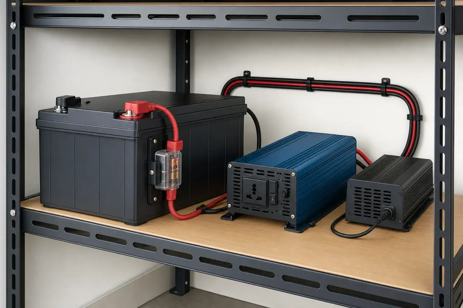
Quick answer: Choose a 12V LiFePO4 battery by calculating the watt-hours your loads need and the highest DC current they can demand. Then verify the exact battery manual for continuous and peak BMS limits, charging requirements, inverter compatibility, temperature limits, physical fit, and allowed series or parallel expansion.
Choose a 12V LiFePO4 battery by energy and current
A backup battery has to pass two separate tests. First, it must store enough energy for the planned runtime. Second, its battery management system (BMS) must be rated to supply the continuous and startup current required by the loads and inverter. Amp-hours alone do not answer both questions.
Use the exact battery manual rather than assuming that batteries with the same Ah label have the same current capability. For example, the Battle Born BB10012 manual lists 100Ah capacity, 100A continuous discharge, and 200A for 30 seconds for that specific model. Those figures are not universal ratings for every 100Ah LiFePO4 battery.
Estimate the energy required for backup runtime
List each load, its operating power in watts, the hours it is expected to run, and which loads can operate at the same time. Watts describe power at a moment; watt-hours (Wh) describe energy used over time. For a fuller explanation of the conversion, see how to calculate watt-hours from amp-hours.
Illustrative assumptions: a set of loads uses 120W in total for six hours, and the candidate battery has a nominal voltage of 12.8V. These are example values, not a prediction of real runtime.
- Load energy:
120W × 6h = 720Wh - Loss-free nominal capacity:
720Wh ÷ 12.8V = 56.25Ah
The 56.25Ah result is only a mathematical minimum. It does not include inverter consumption, conversion losses, cable losses, battery temperature, aging, equipment shutdown behavior, or a reserve for the application.
For AC loads, use the chosen inverter’s documented efficiency at a relevant load where available. Battery energy can be estimated as AC load Wh ÷ inverter efficiency, with efficiency expressed as a decimal. Then add the reserve you have chosen for the outage plan. See why inverter efficiency affects runtime. For DC loads, account for losses in any converter or regulator used.
Compare calculated energy with the battery’s stated nominal voltage and rated energy. A product described as “12V” may not use identical nominal voltage or energy specifications to another product.
Calculate continuous and startup current
Capacity determines potential runtime; current capability determines whether the system can run a load at all. Check the inverter’s steady DC input demand and the highest startup demand from motors, compressors, pumps, or other surge loads.
Illustrative assumptions: the maximum simultaneous AC load is 600W and nominal battery voltage is 12.8V.
- Idealized DC current:
600W ÷ 12.8V = 46.9A
Actual battery current can be higher because an inverter is not loss-free, and DC current changes with operating voltage. Prefer the inverter manufacturer’s stated DC input-current information. If it is unavailable, use documented efficiency and input-voltage information only as an estimate, then confirm compatibility with the equipment manufacturer.
High inverter output can mean high battery-side current. The Samlex SAM-1500C-12 owner’s manual, for example, estimates 150A DC at full continuous output for that specific 1,500W, 12V inverter/charger. Its wiring and fuse instructions apply to that product, not to every 1,500W inverter.
Read continuous and peak BMS ratings separately
The battery’s continuous-discharge rating must cover the sustained DC current required by the system under relevant operating conditions. A peak rating is useful only if the manual states both the allowed current and the allowed duration, and both cover the startup event. A listing that gives a peak-amp number without a duration leaves compatibility unknown.
Also compare the inverter’s input-voltage range and low-voltage shutdown behavior with the battery’s documented operating range and protection behavior. Do not use a BMS protective disconnect as the routine method of switching off the system.
Use this battery decision table before buying
| Screen | Accept the battery only when |
|---|---|
| Stored energy | Its documented rated energy covers calculated load energy, documented conversion losses, and the reserve selected for the application. |
| Continuous load | The documented continuous-discharge rating covers the required DC current. |
| Startup load | The documented peak current and stated duration cover the inverter or load startup requirement. |
| Charging | The charger profile, voltage range, and possible charging current comply with the exact battery manual. |
| Inverter fit | The inverter’s input-voltage range, current demand, shutdown behavior, and surge requirement are compatible with the battery. |
| Expansion | The manual explicitly allows the intended series or parallel arrangement and states any matching requirements. |
| Environment | Documented charging and discharging temperature ranges suit the expected installation conditions. |
| Physical fit | Dimensions, weight, terminals, orientation, clearance, and enclosure rating fit the planned location. |
| Installation scope | Required overcurrent protection, conductors, listings, permits, and local requirements have been addressed for the intended use. |
Confirm charger and inverter compatibility
A “12V” label does not establish charger compatibility. The charger must provide a charging profile, voltage range, and charging current permitted by the battery manufacturer. Do not transfer charge settings from one battery brand or model to another. The Victron Lithium Smart Battery manual, for example, provides settings for its own batteries and calls for a compatible or adjustable charging profile; its values are not universal LiFePO4 settings.
Check every charging source: AC charger, solar charge controller, vehicle charging equipment, and inverter/charger. The total possible charging current must remain within the limit in the battery manual. For charger-selection concepts, see choosing a LiFePO4 battery charger.
If protection disconnects the battery because of temperature or low voltage, follow the manufacturer’s documented recovery procedure. Do not bypass battery protection or improvise a workaround.
Check expansion rules before adding batteries
Series wiring raises bank voltage. Parallel wiring raises bank capacity and may increase the current available from the bank. Neither arrangement should be assumed to be allowed.
Read the exact manual for permission to use batteries in series or parallel, the maximum number allowed, and any requirements for matching model, capacity, age, or state of charge. The cited Battle Born manual permits parallel connections and documents a series limit for its specified model; that permission does not apply to unrelated 12V batteries. If the manual does not explicitly permit the planned configuration, treat it as unsupported.
12V LiFePO4 battery manual checklist
- Nominal voltage, rated Ah, and rated Wh
- Continuous discharge current
- Peak discharge current and permitted duration
- Maximum continuous charge current
- Allowed charging profile and voltage range
- Charging and discharging temperature ranges
- Low-temperature charging protection or heating behavior, if documented
- Series and parallel permissions, limits, and matching rules
- Approved charger or inverter guidance
- Dimensions, weight, mounting orientation, and required clearance
- Terminal type, specified hardware, and torque instructions
- Enclosure or ingress-protection rating, where relevant
- Warranty exclusions relevant to the intended application
- The scope of any certification claim: cells, battery, portable product, or complete energy-storage system
If a seller page conflicts with the model manual, request clarification from the manufacturer before purchase. Treat missing peak duration, expansion permission, or charging specifications as unknown rather than favorable.
Keep standalone backup separate from building wiring
A standalone battery and inverter setup is not automatically suitable for permanent residential energy storage or connection to building wiring. UL Solutions explains that portable-power-pack certification does not by itself establish suitability for a stationary residential installation; UL 9540 addresses the complete energy-storage system.
Never connect an inverter to a household receptacle to energize building wiring. A building-connected or permanently installed system requires appropriate transfer equipment, manufacturer instructions, applicable permits, and direction from a qualified professional and the local authority having jurisdiction.
Use the battery and inverter manuals to determine conductor and overcurrent-protection requirements. Do not open the battery, modify internal components, or bypass its BMS. For medical equipment, confirm backup requirements with the device manufacturer and an appropriate professional; battery capacity alone cannot establish safe operation or required backup duration.
Related guides
Browse this topic →
- Beginner-friendly sizing, runtime & specs
- Solar & charging (MPPT, fast charging, cables)
- Batteries (LiFePO4, cycles, care & storage)
- Safety, cold-weather performance, real-world tips
More in Battery
See all →- Low-Temperature Charging Protection in LiFePO4 Power Stations Explained
- Portable Power Station Expansion Batteries: When Extra Capacity Makes Sense
- Lithium-Ion vs LiFePO4 Batteries Explained
- LiFePO4 vs Lithium-Ion in Cold Weather: Which Holds Up Better?
- Best Storage Charge Percentage: 40% vs 60% vs 80% for Different Battery Chemistries
Keep reading
About this site
Portable Energy Lab publishes practical, independent guides about portable power—clear sizing, safe use, and real-world expectations.
Affiliate disclosure
Some links on this site may be affiliate links. If you buy through these links, we may earn a small commission at no extra cost to you. This helps support our content. Read our affiliate disclosure.