Portable Solar Chargers: Match the Right Type to Your Device

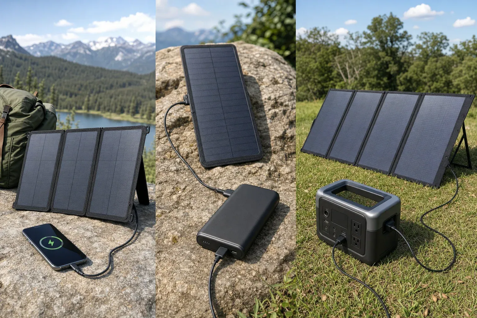
Portable solar panels charging a phone, power bank and portable power station

Quick answer: Choose portable solar chargers from the device backward. Use a regulated USB panel for a phone or USB power bank, and a panel approved for a power station’s DC solar input for larger stored-energy needs. Add battery storage when charging must continue after sunset or through changing sunlight.

How to choose portable solar chargers by device

Start with the input specifications printed on the device or in its manual—not with the panel’s headline wattage. Then match the interface, supported voltage, charging protocol and applicable watt limits. Finally, decide whether you need to store solar energy for later use.

Device Appropriate charger type What to match Storage decision
Phone or small USB device Regulated USB-A or USB-C solar panel Connector, supported USB protocol, voltage profiles, port watts and cable capability Add a power bank when sunlight is variable or charging is needed later.
USB power bank Regulated USB panel matching the bank’s input Input connector, supported protocol, voltage profiles and maximum input watts The power bank provides storage. Check its manual before using pass-through charging.
Phone where one-piece portability is the priority Integrated solar power bank Solar-panel rating, battery input and output ratings, connector and charging protocol Storage is built in, but the panel and battery specifications still require separate checks.
Portable power station Compatible DC solar panel or manufacturer-approved array Input voltage window, maximum open-circuit voltage, current limit, watt limit, connector and polarity The station supplies storage and can provide its supported USB, DC or AC outputs.

If a manual does not state the relevant electrical limits, mark the proposed pairing as unknown. A plug-shaped adapter does not establish electrical compatibility.

Match USB specifications, not just the connector

A USB-C socket does not automatically mean USB Power Delivery (PD) or a particular charging speed. The USB Implementers Forum explains that USB PD lets connected equipment request supported power. Check both manuals to identify the actual voltage profiles and maximum power supported by the panel, cable and device.

  • Connector: Confirm USB-A, USB-C, or the proprietary connector required by the device.
  • Protocol: Check whether both products support USB PD or another protocol needed for a device’s higher charging rate.
  • Voltage: Use a regulated USB output with a fixed or negotiated profile accepted by the device.
  • Power: Compare the panel port’s stated output with the device’s stated input limit. A compliant USB device draws or negotiates a supported level; its current rating does not need to exactly equal the source rating.
  • Cable: Confirm that the cable supports the necessary connector, protocol and power level. An adapter cannot add a charging protocol that the equipment does not support.

Do not connect a phone directly to an unregulated bare-panel output unless the phone manufacturer or an approved charge-controller manufacturer specifically supports that interface.

Calculate the port limit, not only panel watts

Electrical power is calculated as:

watts = volts × amps

For a model-specific example, Goal Zero lists a Nomad 20 solar panel with a 20 W panel rating and a USB output rated at 5 V and up to 2.1 A. The stated USB-port ceiling is:

5 V × 2.1 A = 10.5 W

Under that stated limit, a device connected to that USB port cannot receive 20 W through the USB port. This calculation applies only to the cited version of that product; other panels can have different output-port ratings.

Panel nameplate watts are also not a guarantee of continuous outdoor output. The National Renewable Energy Laboratory describes photovoltaic standard test conditions as 1,000 W/m² irradiance, a 25°C cell temperature and air mass 1.5 in its PV rating reference. Sun angle, shading and operating conditions can change available output.

Match a panel to a portable power station safely

A matching DC plug alone is not enough. Before connecting a panel to a power station, use both manuals to check each item below:

  1. Connector and polarity: Use the specified connector and confirm polarity.
  2. Input-voltage window: Verify that the proposed panel or approved array operates within the station’s published solar-input range.
  3. Open-circuit voltage: Compare the panel or array open-circuit voltage with the station’s stated maximum using the conditions and calculation method required by the manuals.
  4. Current and power limits: Follow the station manufacturer’s published input limits and array instructions.
  5. Configuration: Use only wiring and adapters approved or documented as compatible by the applicable manufacturers.

As an illustration of the labels to compare, the EcoFlow DELTA 2 manual lists an 11–60 V DC solar-input range, 15 A maximum current and 500 W maximum power. The cited EcoFlow 110 W panel manual lists 23.5 V open-circuit voltage, 6.1 A short-circuit current and an XT60i connector. Those are model-specific figures, not universal specifications or approval for another panel, adapter or array.

When battery storage belongs between panel and device

Use a separate power bank or portable power station when you need energy after sunset, expect intermittent sunlight, or prefer to charge the device from a battery’s regulated output. A phone can charge directly from an appropriate regulated USB panel in suitable sun, but direct charging does not create a reserve for later.

A power bank already stores energy, but do not assume it can charge from solar while powering another device. Pass-through behavior and operating limits are model-specific; follow the power bank manual.

Watts, watt-hours and time

Watts (W) measure a rate of power. Watt-hours (Wh) measure energy stored or used over time. They are different units.

Illustrative arithmetic only: if a 100 Wh battery received a constant 10 W with no losses, then:

100 Wh ÷ 10 W = 10 hours

This is not a field charging-time promise. Solar production varies, and charging equipment, cables, battery charging and voltage conversion all affect the result. When a device accepts USB or regulated DC, use that supported output rather than converting battery DC to AC and back again. For an AC appliance, check the power station’s continuous output and model-specific surge capability.

Portable solar charger checklist

  • Device input connector, accepted voltage profiles and maximum input watts
  • Required USB charging protocol, if any
  • Cable connector, protocol support and power capability
  • Panel nameplate rating and the rating of its actual USB or DC output port
  • Power-bank input rating and documented pass-through policy
  • Power-station input-voltage window, open-circuit-voltage limit, current limit and watt limit
  • DC connector type and polarity
  • Manufacturer instructions for the proposed panel, adapter and array configuration
  • Operating-temperature and weather-exposure instructions
  • Certification information for the exact model, where applicable

Final safety checks

Safety claims apply to specific products, not to a product category. UL identifies UL 2056 for standalone power banks and separately discusses UL 2743 for portable power packs and UL 61730-1/-2 for photovoltaic-module safety qualification. Verify any certification claim against the exact model and certification record rather than relying on marketing language.

Keep batteries within their documented environmental limits, keep electrical connections dry unless the manufacturer states otherwise, and do not assume a panel, connector or power station is weatherproof. Never open a battery, bypass its protection circuitry, backfeed a wall outlet or improvise home electrical connections. For medical equipment, obtain device-specific guidance from the equipment manufacturer and an appropriate professional before relying on portable solar power.
Can a Portable Power Station Run an Evaporative Cooler?

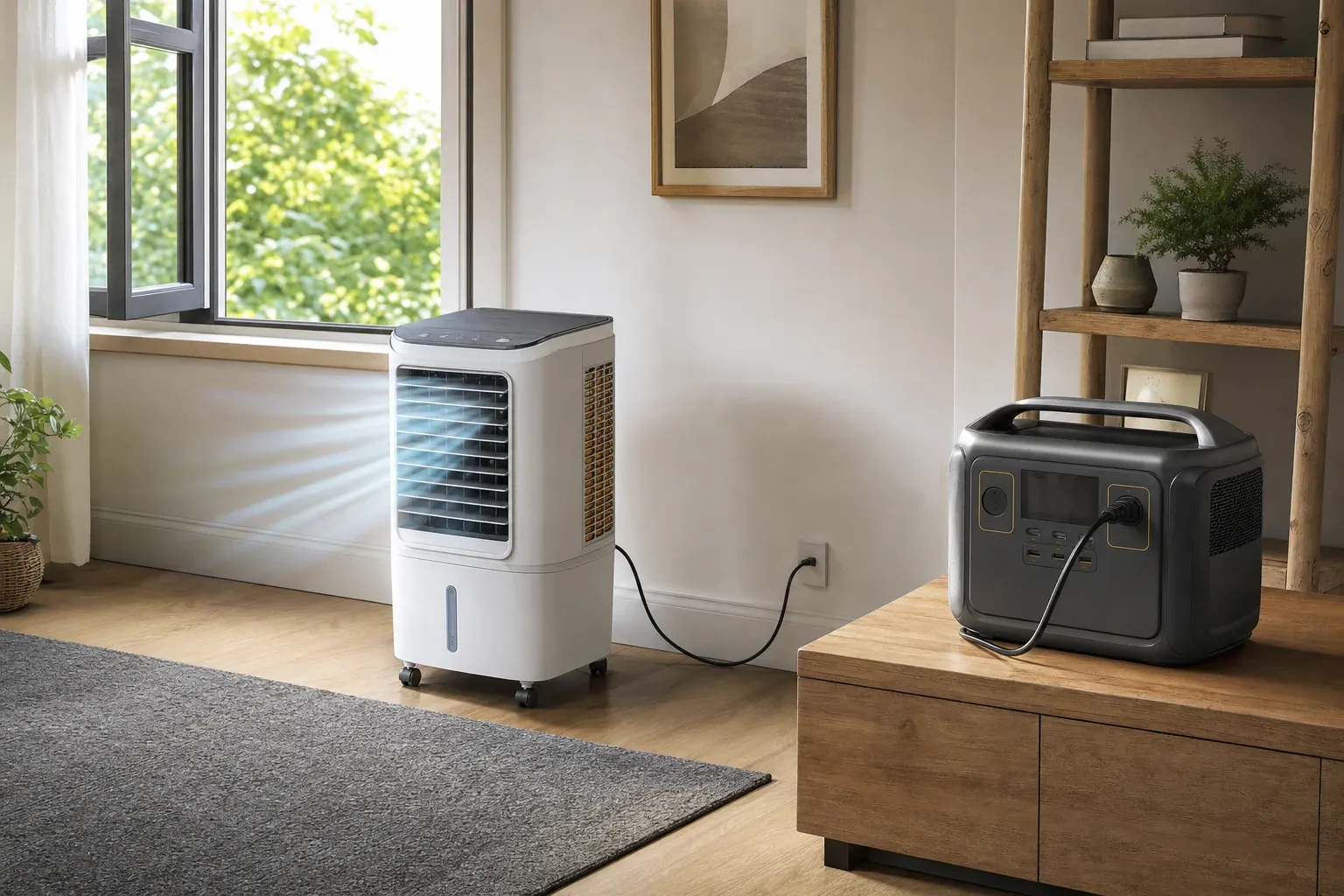
Evaporative cooler powered by a portable power station kept on a separate dry surface

Quick answer: Usually, yes. A portable power station can run an evaporative cooler when its AC voltage and frequency match the cooler, its continuous and applicable surge ratings cover the actual load, and both manuals permit the setup. Estimate runtime with usable AC watt-hours divided by the cooler’s measured average watts.

How to size a portable power station for an evaporative cooler

An evaporative cooler can be a manageable portable-power load, but compatibility is not automatic. A direct evaporative cooler uses a blower to move air through wetted media and a pump to circulate water. The U.S. Department of Energy describes direct systems this way and notes that incoming air needs an exit, commonly through an open window or vent (DOE HVAC guide).

A portable power station for an evaporative cooler must pass five separate checks:

  1. Electrical match: The cooler’s required voltage and frequency must match the station’s AC output.
  2. Continuous output: The station’s continuous AC rating must cover the highest sustained wattage of the mode you intend to use.
  3. Startup output: Documented or safely observed motor-starting demand must remain within the station’s applicable surge capability.
  4. Energy capacity: Usable energy at the AC outlet must support the runtime you need.
  5. Permitted setup: Both manuals must allow the intended location, ventilation, cord arrangement, and proximity to moisture.

These checks apply to a cord-connected cooler plugged directly into the station. Do not modify a plug, improvise an adapter, backfeed a household outlet, or connect a station to permanently wired equipment. A fixed electrical installation needs equipment and professional work approved for that purpose.

Find the cooler’s actual power demand

Start with the cooler’s nameplate and manual. Record the exact model, input voltage, frequency, and listed watts. If it lists only amperes, volts multiplied by amps gives volt-amperes, not necessarily actual watts for a motor load. Obtain wattage from the manufacturer or measure the complete appliance with an appropriately rated plug-in power meter in a dry, manual-approved setup.

Model differences can be substantial, so a generic wattage range is not a dependable sizing method. As one model-specific example, Hessaire lists its MC18M mobile cooler at 85 W total consumption; that value applies to that model, not to evaporative coolers generally (Hessaire MC18M specifications).

Measure fan, pump, and accessory settings

Follow the cooler manual for filling and operation. Then record stable power for every mode you expect to use:

  • Low, medium, and high fan settings, if provided
  • Fan-only operation
  • Fan plus water pump at each intended speed
  • Oscillation and other powered features
  • Automatic modes over a representative interval

For example, the MMBT12/MMBT14 owner’s manual documents blower settings that do not operate the pump, confirming that fan-only and pump-on modes can be distinct loads. The same manual specifies 120 V/60 Hz power and a GFCI-protected receptacle for those models (MMBT12/MMBT14 owner’s manual). Do not apply those requirements or operating details to another cooler without checking its manual.

Enabling the pump or changing fan speed can change power use, but the amount is model-specific. Measuring the complete appliance is more reliable than adding component amp ratings because motor power factor and operating conditions affect actual watts.

Check startup separately from running watts

Nameplate wattage may not describe brief motor-starting demand. Look for manufacturer documentation first. If both manuals permit testing, start the cooler with its normal controls in the most demanding intended mode while watching the meter’s maximum indication and the station’s overload indicators.

Many consumer plug-in meters can miss a short inrush event. A successful start shows that the tested combination worked under those conditions; it does not quantify every unseen peak. Repeated overloads, shutdowns, alarms, or unstable output mean the combination should not be used. Do not assume an evaporative cooler has zero startup surge. For more on that distinction, see surge watts vs. running watts.

Compare watts, watt-hours, and station limits

Watts (W) describe instantaneous power. Compare measured running watts with the station’s continuous AC rating, and compare documented or observed startup behavior with the station’s applicable surge rating.

Watt-hours (Wh) describe stored energy. Battery capacity and inverter output are separate specifications. For example, one specific power-station manual lists 288 Wh capacity, 300 W continuous AC output, and 600 W surge peak as separate ratings (Jackery Explorer 300 Plus manual). Those figures apply only to that model.

Do not treat advertised battery Wh as automatically available at the AC receptacle. Inverter conversion and the station’s operating limits reduce or reserve some energy. Use manufacturer-provided usable AC energy or a safe, documented discharge measurement when available. Otherwise, any reduction factor is only a planning assumption, not a guaranteed efficiency. See usable capacity versus advertised capacity for the distinction.

Evaporative-cooler power decision table

This table is an arithmetic illustration using 500 usable AC Wh after all assumed losses. The loads are examples, not a claimed typical range.

Measured average load Minimum continuous output Estimated runtime from 500 usable Wh
85 W At least 85 W About 5.9 hours
150 W At least 150 W About 3.3 hours
288 W At least 288 W About 1.7 hours
500 W At least 500 W About 1.0 hour

Passing the continuous-output check does not prove startup compatibility. The surge check is separate, and the station manual may set further operating limits.

Calculate runtime from measured watts

Use this equation:

Estimated runtime = usable AC watt-hours ÷ time-weighted average watts

If the cooler stays in one mode, use that mode’s stable measured watts. If settings change during use, measure energy over a representative interval or calculate a time-weighted average. Do not apply a compressor-air-conditioner duty-cycle assumption to an evaporative cooler; its blower and pump may run continuously, depending on its controls.

Illustrative calculation with stated assumptions

Suppose a hypothetical station is labeled 1,024 Wh. For planning only, assume 85% reaches the AC load after conversion and reserve losses. This is an assumption, not a universal efficiency or measured result:

1,024 Wh × 0.85 = 870 usable AC Wh

Suppose meter readings show the cooler using 180 W for 45 minutes of each hour and 90 W for the remaining 15 minutes:

(180 W × 0.75) + (90 W × 0.25) = 157.5 W average

870 Wh ÷ 157.5 W = about 5.5 hours

Actual runtime can differ with operating mode, battery state, temperature, inverter behavior, and automatic shutoff settings. Replace the assumed 85% factor with documented or measured usable AC energy whenever possible.

Keep the station dry and maintain airflow

An evaporative cooler combines electricity with a water reservoir, pump, fill connection, or wet media. Keep the power station outside every spill, spray, drainage, and refill path. Do not place it on the cooler, beside an overflow point, or where damp exhaust reaches it. Preserve the ventilation clearances required by both products.

Power-station restrictions vary. The cited Explorer 300 Plus manual, for example, calls for a dry, ventilated location and prohibits exposure to rain or wet environments. That is model-specific guidance, but it illustrates why the station’s own manual must control placement.

Confirm whether the cooler manual requires GFCI protection and whether the proposed supply arrangement actually provides it. Do not assume every power station has GFCI protection merely because it has an AC receptacle. Follow current local electrical requirements, or consult the authority having jurisdiction or a qualified electrician when the arrangement is unclear. See grounding and GFCI with portable power stations for related considerations.

Certification has a defined scope. UL Solutions explains that UL 2743 covers portable power packs for activities such as camping or temporary loss of normal power; that certification does not make a pack a permanently installed residential energy-storage system under UL 9540 (UL Solutions portable power pack guidance).

Nameplate and plug-in-meter checklist

  • Cooler make and exact model number
  • Required input voltage and frequency
  • Nameplate watts or amperes
  • Fan-only watts at each intended speed
  • Fan-plus-pump watts at each intended speed
  • Watts used by oscillation or other accessories
  • Documented startup demand or safely observed maximum
  • Any station overload, alarm, or shutdown during startup
  • Station continuous and surge AC ratings
  • Battery capacity and documented or assumed usable AC Wh
  • Low-load or automatic AC shutoff behavior
  • GFCI instructions for the cooler and supply
  • Indoor/outdoor rating and dry-placement requirements
  • Cooler exhaust-air and station ventilation clearances

The right station is not determined by battery capacity alone. Confirm the electrical match, measure the complete cooler in its intended modes, verify startup separately, and calculate runtime from usable AC energy. If either manual prohibits the location or power arrangement, choose a different setup rather than improvising around the restriction.

Solar Generator With Panels Included: 7 Checks Before Buying

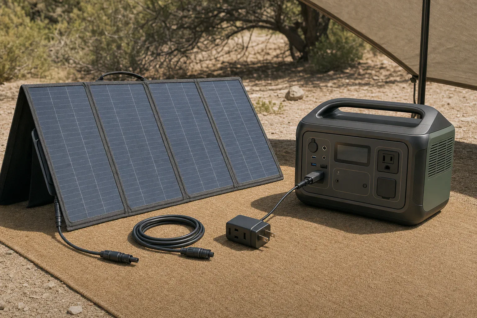
Portable power station, folding solar panel, charging cable, and adapter arranged for a bundle audit

Quick answer: A solar generator with panels included is complete only when the exact panel model is approved for the station’s solar-input voltage, current, and watt limits, and the selected bundle includes the required charging cable and adapter. Confirm package contents and warranties in manufacturer documents, not only a retailer title or product photo.

Audit a solar generator with panels included before ordering

“Panels included” does not necessarily mean every part needed for solar charging is in the cart. A product page may combine station-only, one-panel, and multi-panel variants; the panel may also need a specific cable or input adapter. Treat the bundle as a set of separately verifiable components rather than relying on its title.

  1. Exact power-station model: Record the complete model name and, where relevant, revision. Product-family names alone can hide different solar-input ports or limits.
  2. Exact panel model and quantity: Confirm the panel model number and count. Similar-looking panels can have different electrical ratings, leads, or connectors.
  3. Panel electrical ratings: Find rated power, open-circuit voltage (Voc), operating voltage (Vmp), short-circuit current (Isc), and operating current (Imp).
  4. Station solar-input limits: Check the allowed voltage range, maximum voltage, current limit, watt limit, port count, and any per-port restrictions.
  5. Cable and connector path: Identify the connector at the panel, both ends of each cable, the station input, and the polarity shown in the official connection instructions.
  6. Selected variant’s package contents: Check the option actually selected in the cart. Do not assume contents shown for another variation apply to yours.
  7. Warranty scope: Read coverage for the station, panel, cable, and adapters separately. Terms can differ among components and sales channels.

Use this bundle-audit table

Compare the seller listing against the manufacturer’s manual, specifications, package list, connection diagram, and warranty policy. Save copies or screenshots with the order record, because product pages and variants can change.

Item What to verify Best document to check Action if unclear
Power station Exact model, solar-input voltage range, maximum voltage, current and watt limits, input-port count Official manual, specification page, or input label Do not approve the bundle until the exact model and limits are known.
Solar panel Model, quantity, rated watts, Voc, Vmp, Isc, and Imp Panel label, manual, or official specifications Compare every published value with the station documentation.
Solar charging cable Connector at both ends and supported connection configuration Package list and official connection diagram Obtain the manufacturer-specified cable if it is not included.
Adapter Input/output connector types and polarity Official connection guide or adapter specifications Use only an approved adapter; do not choose one by plug shape alone.
Multi-panel hardware Any required adapters or connectors for the intended number of panels Station manual or manufacturer expansion guide Buy the specified hardware before expanding the array.
Extension cable Whether included, connector compatibility, and electrical rating Package list and cable specifications Add an approved cable if the supplied lead cannot reach the planned panel location.
Delivery Number of cartons and whether panels ship separately Order details, package list, and seller confirmation Document missing cartons promptly rather than assuming an accessory was omitted.
Warranty Term, eligible seller, registration rules, proof-of-purchase requirements, and exclusions Official warranty policy and exact product page Request written clarification when documents conflict.

Does the included panel fit the station’s input limits?

A matching connector is not proof of electrical compatibility. Check voltage, current, and power independently for the exact models. If the manufacturer does not document a pairing or configuration, do not infer approval from a retailer listing.

Voltage: check operating range and maximum input

Compare the panel’s published operating voltage with the station’s stated solar-input range. Also check the panel’s Voc against the station’s maximum permitted input voltage using the manufacturer’s approved configuration. Solar-panel nameplate values are commonly stated under standard test conditions, and real outdoor conditions can differ. Follow the manufacturer’s documented arrangement rather than creating an undocumented series or parallel configuration.

Current: do not assume how a station handles excess available current

Compare the panel’s Imp and Isc with the station’s current specifications and connection instructions. Manufacturers may describe current limits differently. If the documentation does not state whether a proposed pairing is accepted, prohibited, or input-limited, the result is unknown until the manufacturer confirms it in writing.

Wattage: nameplate power is not a charging promise

Panel watts describe rated power under specified test conditions. A station’s solar-input watt limit describes its designed input limit. A panel rated at or above that limit does not establish that the station will capture every available watt, and panel wattage alone cannot determine a guaranteed recharge time.

Illustrative documented pairing: Jackery Explorer 1000 v2 and SolarSaga 200W

This example shows how to read published figures for a manufacturer-documented pairing. It is not a wiring rule or approval for other stations, panels, adapters, or configurations.

Jackery lists the Explorer 1000 v2 solar-input range as 16–60V, with a 10.5A and 200W maximum per port. It lists totals of 21A and 400W when both ports are used, identifies the input as DC8020, and says one or two panels use included cables while a four-panel configuration requires two SolarSaga adapters. Jackery’s Explorer 1000 v2 basic information

Jackery publishes the SolarSaga 200W panel at 200W ±5%, 22V Voc ±5%, 18V Vmp ±5%, 12.5A Isc ±5%, and 11.5A Imp ±5% under its stated standard test conditions. Its separate package list names a three-meter multifunction cable and a DC8020-to-DC7909 adapter. Jackery’s SolarSaga 200W specifications

Illustrative tolerance calculation: using the published positive or negative tolerance as an arithmetic assumption:

  • Voc: 22V × 1.05 = 23.1V.
  • Vmp: 18V × 0.95 = 17.1V.
  • Imp: 11.5A × 1.05 = 12.075A.
  • Rated power: 200W × 1.05 = 210W.

The calculated voltage figures fall within the station’s published 16–60V range. The panel’s stated current and possible power tolerance, however, exceed the listed per-port figures. Because Jackery sells and documents this pairing, it is manufacturer-supported; the specifications alone do not show how much current or power the station will accept in every condition. They therefore do not support a promise of 200W or more of real charging input.

For the US “Explorer 1000 v2 + SolarSaga 200W” option, Jackery’s package list names one station, one AC charging cable, one panel, and one multifunctional solar charging cable. Its station-only option does not include the panel or solar cable. That distinction is why the selected variant—not the shared product page—must be audited. Jackery Solar Generator 1000 v2 package options

Trace every cable and connector from panel to station

Map the complete charging path before purchase: panel output, permanently attached lead if present, detachable charging or extension cable, any adapter, and the station input. Product photos are not enough because visually similar connectors can have different dimensions or polarity.

  • Solar charging cable: Without the correct cable, an included panel may not connect to the station.
  • Input adapter: A cable may fit the panel but end in the wrong plug for the station.
  • Multi-panel adapter: This may be needed only when adding panels, not for the initial included panel.
  • Extension cable: It may be necessary to put the panel in sunlight while keeping the station in a suitable dry location.
  • Support or mounting hardware: Do not assume it is included unless it appears in the exact package list.

Use only connection methods specified for the exact products involved. Do not reverse polarity, splice unfamiliar cables, or assume a third-party adapter is appropriate because its plug fits.

Keep capacity, output, and solar input separate

Watts (W) measure a rate of power; watt-hours (Wh) measure stored or consumed energy. A 1,000Wh station and a 200W panel cannot be divided to create a guaranteed five-hour solar recharge claim. Sunlight, panel orientation, temperature, conversion behavior, battery-management behavior, and the station’s charging profile all affect actual results.

The station’s AC output rating is also separate from solar compatibility. Continuous and surge output ratings help determine whether the station can run an appliance; they do not tell you whether a solar panel is approved for its input.

Confirm warranty coverage for each bundle component

Check the official policy and the exact product page for the relevant SKU and seller. Confirm when coverage begins, whether registration changes the term, what proof of purchase is required, and whether panels and accessories have terms separate from the power station.

Official pages can conflict. Jackery’s cited warranty policy lists certain station families at 3+2 years and lists SolarSaga 200W, 100W, and 80W products at 2+1 years, while its SolarSaga 200W product page advertises a 3+2-year warranty. Obtain written confirmation for the exact panel SKU and sales channel instead of assuming the more favorable term applies. Jackery warranty policy

Make a buy-or-wait decision

Buy when the precise station and panel models are identified, the manufacturer documents the pairing, the selected package list includes every required cable and adapter, and warranty terms are clear.

Wait for clarification when a listing omits electrical ratings, uses conflicting model names, relies on connector photos, promises accessories absent from the official package list, or leaves warranty coverage and input-limit behavior unresolved. Keep the listing, official documents, and the seller’s written response with the order record.

AC Extension Cord Voltage Drop With Portable Power Stations

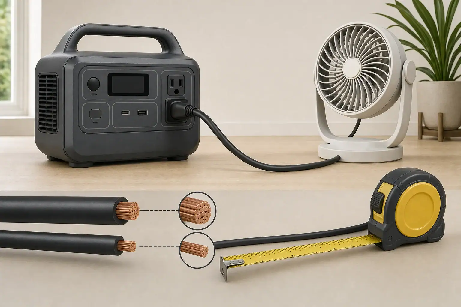
Portable power station powering an appliance through an AC extension cord with conductor-size comparison

Quick answer: For AC extension cord voltage drop with portable power stations, use the appliance nameplate amps first. Choose the shortest listed cord whose printed rating covers the load, then check gauge and length with a voltage-drop calculation. Lower AWG numbers generally mean larger conductors and less calculated drop.

AC extension cord voltage drop: gauge, length, and load

An extension cord has to meet three separate limits: the appliance demand, the cord’s printed rating, and the portable power station’s AC-output limits. Wire gauge and length affect voltage drop, but a favorable calculation does not make an underrated cord or power station suitable.

For a 120 V setup, use the table below as a conservative planning check based on a 3% calculated voltage-drop target. It assumes copper conductors at a 20°C reference temperature and the stated current flowing continuously. It is not an ampacity table, a legal limit, or a guarantee that every appliance will operate correctly.

Approximate maximum one-way cord length at a 3% calculated voltage-drop target
Assumed load 16 AWG 14 AWG 12 AWG 10 AWG
600 W / 5 A 90 ft 143 ft 226 ft 360 ft
1,200 W / 10 A 45 ft 71 ft 113 ft 180 ft
1,500 W / 12.5 A 36 ft 57 ft 91 ft 144 ft
1,800 W / 15 A 30 ft 48 ft 75 ft 120 ft

How to use the table: Select a practical cord shorter than the listed length, then confirm its printed current or wattage rating covers the appliance. Also confirm the station’s continuous AC-output rating, any receptacle-specific limit, and its total output shared with other connected loads.

The calculation uses copper resistance values of approximately 4.02, 2.52, 1.59, and 0.9988 ohms per 1,000 feet for 16, 14, 12, and 10 AWG respectively at 20°C, from the NIST Copper Wire Tables. Actual cord assemblies can differ because conductor temperature, stranding, plugs, receptacles, and contact condition add variables.

Find the appliance current before choosing a cord

Use the appliance nameplate input amperage when it is available. Read the appliance manual as well, particularly if it gives extension-cord instructions or identifies a startup requirement.

For single-phase AC, the relationship is:

watts = volts × amps × power factor

Dividing watts by 120 V is therefore a useful estimate only for a load with power factor near 1. For example, a hypothetical 1,200 W resistance load at 120 V draws about 10 A. Motors and electronic power supplies can have a power factor below 1, so their real watts alone may not reveal current. The DOE Electrical Science handbook explains the relationship among true power, apparent power, and power factor.

If power factor or starting current is unknown, do not invent a multiplier. Use the appliance nameplate and manual. A motor may draw more current while starting, but the amount and duration depend on the specific appliance.

Calculate AC extension cord voltage drop

For a two-conductor 120 V load circuit, an idealized calculation is:

voltage drop = 2 × one-way length (ft) × current (A) × resistance (ohms per 1,000 ft) ÷ 1,000

The factor of two accounts for the outgoing and return conductors. Convert the result to a percentage with:

drop percentage = voltage drop ÷ supply voltage × 100

Illustrative calculation: 1,200 W resistance load on a 50-foot cord

Assumptions: 120 V station output, power factor near 1, 10 A load current, a 50-foot one-way cord length, and the NIST 20°C reference resistance. This is a calculation, not a measurement of a particular cord or station.

  • 16 AWG: 2 × 50 ft × 10 A × 4.02 ohms/1,000 ft ÷ 1,000 = 4.02 V. That is about 4.02 ÷ 120 × 100 = 3.35%.
  • 12 AWG: 2 × 50 ft × 10 A × 1.59 ohms/1,000 ft ÷ 1,000 = 1.59 V. That is about 1.59 ÷ 120 × 100 = 1.33%.

Under these assumptions, the 12 AWG cord has less calculated drop than the 16 AWG cord. Neither result establishes the cord’s allowable current rating; the cord’s own printed marking remains controlling.

Check the appliance, cord, and power station separately

  1. Appliance: Check nameplate amps, operating voltage, and manufacturer instructions. Do not assume that a station can start a motorized appliance just because its listed running watts fit.
  2. Cord: Check the printed current or wattage rating, conductor gauge, jacket marking, and indoor or outdoor designation. Select a listed cord appropriate for the environment and inspect it before use.
  3. Power station: Check the exact model’s continuous AC-output rating, total shared-output limit, surge specification, receptacle limits, and displayed warnings or fault indicators.

The DOE Electrical Safety handbook identifies conductor gauge, cord length, intended use, inspection, environmental markings, and NRTL listing as relevant cord-selection considerations.

Power-station specifications are model-specific. For example, the EcoFlow DELTA user manual lists AC specifications and protection functions for that model only. Do not transfer those values to another station. A station’s surge rating also does not authorize operation above its continuous rating.

When a shorter or heavier cord may help

A cord may be worth investigating when an appliance runs directly from the station but not through the cord, a motor struggles to start, lights dim markedly under load, or a shutdown appears only with the extension cord connected. These signs do not prove voltage drop: overload, startup demand, temperature protection, a low battery, appliance protection, or a damaged connection can also be involved.

Use a controlled direct-versus-cord check

  1. Disconnect other AC loads. Note the station battery level and any displayed fault indication.
  2. If the appliance manufacturer permits it, connect the appliance directly to the station and observe whether it operates normally.
  3. Repeat with the extension cord, without changing the appliance or station settings.
  4. If the issue occurs only with the cord, inspect its printed rating, length, gauge, plugs, and receptacle fit. A shorter appropriately rated cord or a lower-AWG listed cord can reduce calculated drop.
  5. Stop using the cord if insulation is damaged or if there are bent contacts, discoloration, an abnormal odor, arcing, or an unusually hot plug or connector.

Do not repeatedly reset an overload or protection fault without identifying the cause. Follow the appliance and station manuals for model-specific warnings and service guidance.

Watts, watt-hours, and runtime

Watts (W) describe instantaneous load and help determine whether the station and cord can support an appliance. Watt-hours (Wh) describe stored energy and are used for runtime planning.

A simple Wh ÷ W result is an idealized estimate, not a promised AC runtime. Inverter operation and cord resistance consume some energy, and results vary with the station, load, cord, connections, and operating conditions.

This article covers cords connected to a power station’s AC receptacle. Solar-extension cables are DC equipment with different voltage, current, connector, polarity, and compatibility requirements; select them only according to the solar source and power-station manuals.

Bottom line

Start with nameplate amps, verify the printed ratings of the appliance, cord, and power station separately, and calculate drop for the intended one-way cord length. When two cords meet all applicable ratings, the shorter cord or the one with the lower AWG number will generally have less calculated voltage drop.

Can a Power Station Run a Corded Leaf Blower?

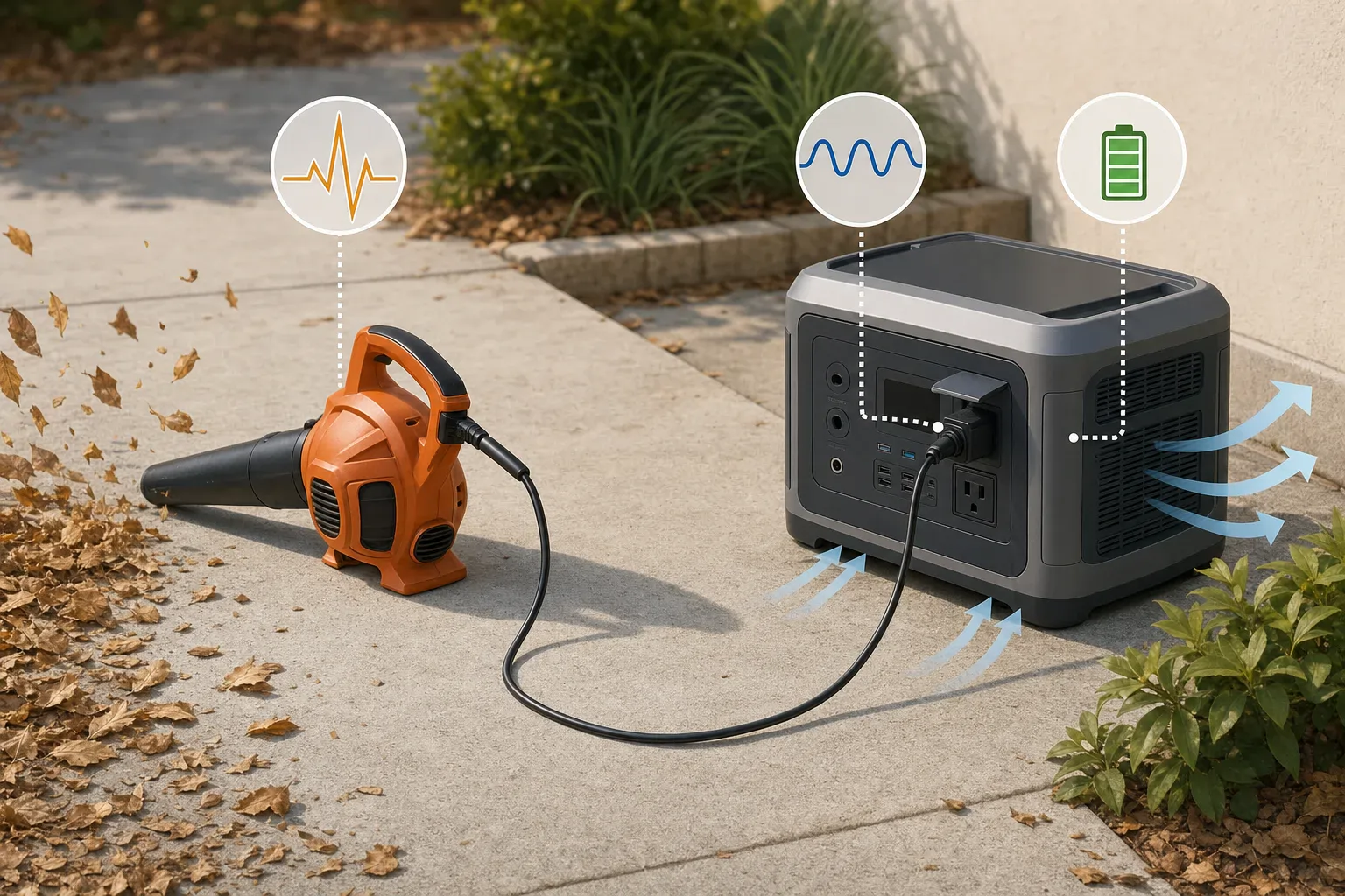
Illustration of a corded leaf blower connected to a portable power station on a dry driveway

Quick answer: A portable power station can run a corded leaf blower only when its AC output supports the blower’s running load and its surge capability starts the motor. Check voltage, frequency, output limits, and startup behavior separately. Battery watt-hours affect operating time, not whether the blower can start.

Size a portable power station for a corded leaf blower

There are three separate questions: can the inverter supply the blower while it runs, can it tolerate motor startup, and how long can the battery supply that load? A large battery does not compensate for an undersized AC inverter.

Start with the exact model numbers and manuals. Confirm that the power station’s AC output voltage and frequency match the blower’s label, then compare the station’s continuous output, any outlet or total-output current limit, and its published surge specification.

Use the blower label as a screening check

Look for volts, amps, watts, frequency, and the model number. If the label provides volts and amps, calculate:

VA = volts × amps

For example, BLACK+DECKER describes its BV6600 as having a 12-amp motor and variable-speed selections. If a 120V supply applies, the nameplate screening calculation is:

120V × 12A = 1,440VA

This is not proof that the blower uses 1,440W. For AC loads, apparent power is volts × amps, while true power depends on power factor: watts = volts × amps × power factor. BLACK+DECKER does not publish measured running watts, power factor, or startup demand for the BV6600 on its cited product page. Treat those values as unknown until documented or measured. See the BLACK+DECKER BV6600 product page and Fluke’s electrical glossary.

When power factor is unavailable, use nameplate VA as a cautious screening figure and check the station manual for watt, VA, and AC-current restrictions. Read more about the distinction in VA vs. watts for portable power stations.

Startup is a separate limit

A corded blower motor can draw more power while starting than after reaching speed. There is no verified universal startup multiplier for corded leaf blowers, so do not assume that a stated surge rating guarantees compatibility. Compare documented startup demand, if available, with the station’s surge rating and its stated conditions. Surge output is not continuous output.

As one specification example, EcoFlow’s US DELTA 2 manual lists a 1,024Wh battery, 1,800W total AC output, and 2,700W surge output. Those figures apply to that model only and do not certify it for a particular blower. The manual also says X-Boost is not compatible with every appliance and is more suitable for heating devices; do not use that feature as evidence that a blower motor will run. See the EcoFlow DELTA 2 manual.

Leaf-blower power-station decision table

What you find Practical decision
Station continuous output is below the blower’s measured maximum running watts Do not use the pairing.
Nameplate VA is close to the station’s watt, VA, or AC-current limit Treat the match as marginal; obtain better load data before relying on it.
Running load appears to fit, but startup demand is unknown Check both manuals and perform a normal, supervised startup test from a full charge with no other loads connected.
The station reports overload, shuts down, or trips during startup The pairing is not compatible under those conditions. Do not bypass protection.
Running demand and startup both remain within documented limits The electrical match is promising; calculate runtime from average operating watts.

A 1,500W station is too close to a 1,440VA nameplate calculation to support a universal compatibility claim. Watts and VA are different quantities, and the blower’s startup demand remains unknown. More continuous-output and surge headroom is preferable, but the manuals and a successful normal startup are the deciding evidence.

Estimate corded leaf blower runtime

Runtime depends on energy delivered at the AC outlet and the blower’s average power during real work:

runtime (hours) = usable AC energy (Wh) ÷ average blower power (W)

Do not assume all nominal battery watt-hours reach the AC outlet. Conversion losses, the station’s shutdown reserve, temperature, battery condition, and operating mode can change usable output. See usable capacity versus advertised capacity for why battery nameplate capacity is not an AC-runtime guarantee.

Illustrative calculation, not a test result

Assume a station has 1,024Wh of nominal battery capacity and a blower averages 1,200W during the intended work cycle:

1,024Wh ÷ 1,200W = 0.853 hours

0.853 hours × 60 minutes/hour = about 51 minutes

That is an ideal mathematical ceiling, not an expected field runtime, because it assumes every nominal watt-hour is delivered to the blower. If a controlled record instead showed 850Wh delivered at the AC outlet under comparable conditions, the estimate would be:

850Wh ÷ 1,200W = 0.708 hours, or about 42.5 minutes

For a useful personal estimate, record the blower’s average watts during representative use and divide a known usable AC-energy result by that average. Variable speed and pauses can change average consumption, so measure the work pattern you actually expect.

Safe setup and pre-use checks

  1. Identify both models. Record the blower’s voltage, frequency, and amps or watts; record the station’s continuous AC watts, surge specification, and AC-output limits.
  2. Read both manuals. Confirm output compatibility and follow any manufacturer restrictions for motor loads or operating environment.
  3. Use an appropriate extension cord. Follow the blower manual’s model-specific wire-gauge and length table rather than copying a table from another tool.
  4. Inspect before use. Do not use damaged plugs, loose receptacles, cut insulation, or worn cords.
  5. Keep equipment dry and ventilated. Keep the station, plugs, and cord connections away from standing water, wet grass, and debris while preserving the station’s required ventilation clearances.
  6. Test with no other loads. Fully charge the station, disconnect other devices, start the blower in the intended mode, and watch for an overload warning or shutdown.
  7. Stop for warning signs. Disconnect if the station overloads, the motor sounds unstable, or a plug or cord becomes abnormally hot. Never defeat protective devices or remove a grounding pin.

For example, Toro’s manual for blower model 51619 calls for a polarized, UL-listed extension cord recommended for outdoor use and provides a model-specific gauge-by-length table. It also warns against damaged cords, standing water, and wet grass. Those instructions are not a universal cord table for other blowers. See the Toro 51619 operator’s manual.

OSHA’s cord-safety guidance likewise emphasizes factory-assembled cord sets, inspection, suitable service markings, strain relief, and moisture control. Its regulatory requirements apply to covered workplaces, not automatically to every home, but the hazard-control guidance is relevant. See OSHA’s extension-cord and electrical-safety guidance.

When not to use a power station with a blower

Do not use the pairing when the blower exceeds the station’s continuous output, startup causes an overload, the match is marginal and necessary limits cannot be verified, or the required cord arrangement conflicts with either manual. Adding battery capacity may extend runtime, but it will not make an undersized inverter start a motor.

Can a Portable Power Station Run a Toaster Oven?

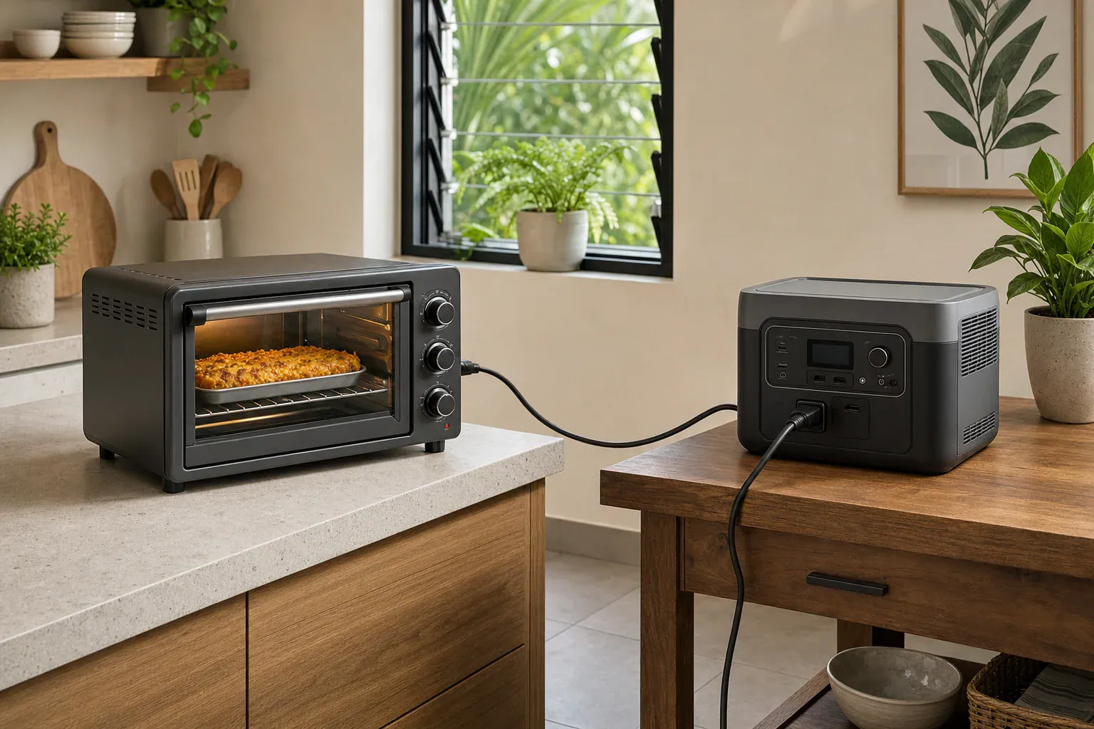
Illustration of a toaster oven plugged directly into a portable power station on separate surfaces

Quick answer: Yes. A portable power station can run a toaster oven when its continuous AC output meets or exceeds the oven’s nameplate input watts, with room for any other simultaneous loads. Battery watt-hours affect cooking-session count, but actual energy use varies with thermostat cycling, recipe settings, and AC conversion losses.

Can a portable power station run a toaster oven safely?

Start with the electrical label on the exact toaster oven rather than a generic wattage range. Compare the oven’s input watts with the power station’s continuous AC output, not its short-term surge rating. Also confirm that the station provides the voltage and frequency required by the appliance.

For example, the Hamilton Beach 31190-series manual lists 120V, 60Hz, 1,500W. The Breville BOV670 manual lists 120V, 60Hz, 1,800W. Those ratings apply only to the models covered by those manuals.

  1. Find the oven’s input watts on its rating label or in its manual.
  2. Find the station’s total continuous AC-output rating.
  3. Add the watts of every load that will run at the same time.
  4. Use the pairing only if the total remains within the station’s continuous-output limit.

Two documented compatibility examples

This is a comparison of published ratings, not a performance test or a runtime guarantee.

Published toaster-oven ratings compared with power-station AC-output ratings
Power station Published capacity and AC output 1,500W Hamilton Beach oven 1,800W Breville oven
EcoFlow DELTA 2 1,024Wh; 1,800W continuous total AC output; 2,700W surge Passes the rating screen; 300W remains for other loads At the published continuous-output ceiling
Jackery Explorer 1000 Plus 1,264.64Wh rated capacity; 2,000W rated total AC output; 4,000W surge peak Passes the rating screen; 500W remains for other loads Passes the rating screen; 200W remains for other loads

The DELTA 2 manual instructs users to keep total loaded-device power at or below 1,800W. An oven rated at the station’s exact ceiling leaves no published allowance for another AC appliance. A modest margin can be practical, but neither oven manual establishes a required margin percentage.

Watts decide whether it runs; watt-hours estimate cooking sessions

Watts (W) are the rate of power use. They determine whether the station can support the oven while its heating elements are energized.

Watt-hours (Wh) are stored energy. They help estimate how many cooking sessions the battery may support. However, a station’s advertised battery capacity is not automatically the energy available from its AC outlets. Inverter conversion and the station’s own operating consumption reduce delivered AC energy. See usable capacity versus advertised capacity for the distinction.

The cited manufacturer specifications provide battery-capacity ratings, but they do not establish usable AC watt-hours for these toaster-oven loads. Exact session counts cannot be derived from the advertised Wh figure alone.

Does a toaster oven need startup or surge headroom?

The manuals for the two example ovens do not publish separate startup-watt figures. There is no basis here for assuming that either oven requires twice its nameplate wattage or any other generic startup multiplier.

Use the station’s continuous-output rating as the primary limit for a heating appliance. Surge output describes brief overload capability; it does not make a lower-continuous-output station suitable for sustained cooking. If the manuals for your exact oven or power station state a model-specific starting requirement, follow those instructions. For more on the distinction, see surge watts versus running watts.

Why thermostat cycling changes energy use

Nameplate watts should not be treated as a guaranteed average draw for every recipe. The Breville BOV670 manual states that the top and bottom elements cycle on and off in Bake mode to regulate temperature. The station must still support the oven’s heat-on demand, even when the session’s average consumption is lower.

No universal cycling percentage is available. Preheating, selected mode and temperature, food load, room conditions, and door opening can affect energy used during a session. A full-nameplate calculation is useful as a conservative planning assumption, but it is not a measured runtime result.

Illustrative watt-hour calculation

Assume, only for this example, that a 1,500W oven draws its full nameplate input for a complete 20-minute session, including preheating:

1,500W × (20 ÷ 60 hours) = 500Wh per session

Using the Jackery Explorer 1000 Plus’s published 1,264.64Wh battery capacity as an idealized comparison:

1,264.64Wh ÷ 500Wh = 2.53 idealized sessions

This is not a claim that the station will provide 2.53 sessions. AC conversion and station overhead reduce energy delivered at the outlet, while thermostat cycling can reduce the oven’s energy consumption below the full-power assumption. The actual number of complete sessions is unknown until it is measured with the intended recipe.

How to measure your own cooking-session energy

  1. Use the same cooking mode, temperature, preheat routine, and duration that you expect to repeat.
  2. Disconnect unrelated loads so the oven is the only meaningful load on the station.
  3. Record the watt-hours used for one complete preheat-and-cook session from the station display, if it provides an energy reading, or use a plug-in energy meter rated for the appliance load and used according to its instructions.
  4. Repeat the observation, since thermostat cycling and cooking conditions can vary.
  5. When available, use a manufacturer-published usable-AC-energy figure measured under comparable conditions rather than substituting battery capacity.

Once both values are known, calculate complete sessions as:

complete sessions = floor(usable AC Wh ÷ measured Wh per session)

Operating and cord precautions

  • Follow the toaster oven’s manual before using an extension cord or power strip. The Breville BOV670 instructions recommend a dedicated outlet and do not recommend an extension cord or power strip.
  • If the oven manual permits an extension cord, use one with an electrical rating at least equal to the appliance. The Hamilton Beach 31190-series instructions provide model-specific extension-cord guidance.
  • Keep every simultaneous load within the power station’s stated limits. Do not rely on surge output for sustained cooking.
  • Set the toaster oven on a stable surface and maintain the clearances required by its manual. Keep the power station separate from the oven’s heat, steam, grease, and spills.
  • Do not operate the toaster oven unattended. The Hamilton Beach instructions also direct users to unplug the appliance when it is not in use.
  • Plug the appliance into the power station’s AC outlet only. Never connect a power station to a household receptacle or use it to backfeed building wiring.

Bottom line

A toaster oven is a high-draw cooking load, so the continuous AC-output number is the first pass-or-fail check. Match the exact oven label to the exact station manual, avoid competing loads, and measure watt-hours for the recipe you actually plan to cook. That approach is more reliable than generic toaster-oven wattage ranges or advertised battery capacity alone.

Solar Panel Rated Watts vs. Real Charging Output

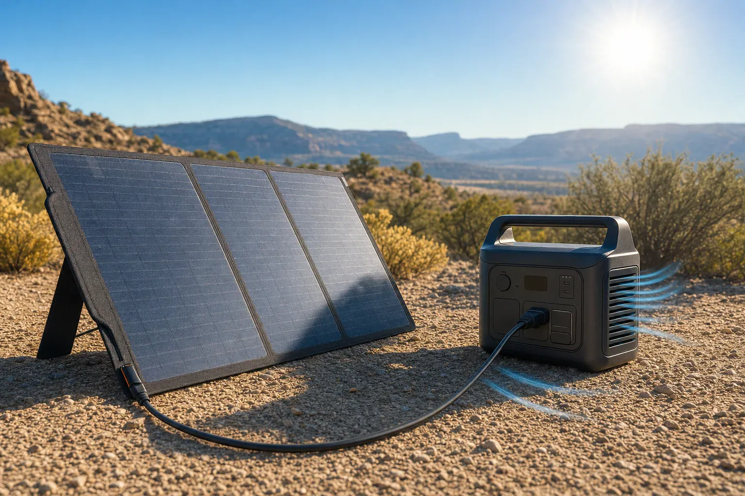
Folding solar panel connected safely to a portable power station in direct sunlight

Quick answer: Solar panel rated watts are a maximum-power rating measured under standardized test conditions, not guaranteed charging input. Real charging output varies with sunlight, panel temperature, orientation, cabling, and the power station’s permitted solar voltage, current, wattage, and battery-charging behavior.

What do solar panel rated watts mean?

Solar panel rated watts describe the panel’s maximum-power rating under defined test conditions. They are an instantaneous power value, not a promise that the panel will continuously deliver that number of watts to a portable power station.

Standard test conditions use irradiance of 1,000 watts per square meter and a solar-cell temperature of 25°C (77°F), according to the U.S. Department of Energy. They also specify an Air Mass 1.5 solar spectrum. NREL notes that these standardized conditions are useful for ratings but “do not represent actual operating conditions” (NREL PDF).

Outdoor conditions and the equipment connected to the panel differ from those rating conditions. As a result, a lower number on a station display is not, by itself, evidence that the panel is defective.

Keep watts, displayed input, and watt-hours separate

Number What it means Do not confuse it with
Panel rated power (W) The nameplate maximum under its specified test conditions. A guaranteed field charging rate.
Panel-terminal power (W) Voltage multiplied by current at the panel terminals at a particular moment. The station display unless the manufacturer says it measures there.
Displayed charging input (W) Power reported by the station at its own model-specific measurement point. A laboratory measurement of panel output.
Battery capacity or energy (Wh) An amount of energy stored or transferred over time. Instantaneous charging power.

Watts and watt-hours are different units. If input remained at 100 W for two hours, the energy reaching that measurement point would be 200 Wh. That does not necessarily mean the battery stored exactly 200 Wh: the station’s charging electronics, battery-management behavior, and any active loads can affect stored energy or the displayed net result.

Why the station may show less than the panel rating

The charging path is panel → cable and connectors → the station’s solar charge controller → battery. The power accepted by the station is limited by the power available from the panel under current conditions and by the station’s documented input requirements.

  • Sunlight intensity, shading, panel aim, and cell temperature can change the power available from the panel.
  • Cables, connectors, and the approved system configuration can affect the charging path.
  • The station may have a permitted PV voltage range, maximum input current, and maximum solar-input wattage.
  • The station may reduce charging under some battery-state or temperature conditions.

For example, the EcoFlow DELTA 2 manual lists solar charging at 500 W maximum and requires panel output voltage to remain within 60 V (manufacturer manual). Those are limits for that model, not general limits for all power stations.

A larger panel therefore does not guarantee an equally large displayed input. More importantly, wattage alone is not a compatibility check. Consult the station manual before connecting any panel or array, and do not exceed its stated PV voltage limit.

Specifications to compare before connecting solar

Specification What it describes What to check
Panel Pmax Nameplate maximum power. Use it as a standardized rating, not an output promise.
Panel Vmp Voltage near rated maximum-power operation. Check the station can operate with the panel at this voltage.
Panel Imp Current near rated maximum-power operation. Compare with the station’s stated input-current limit.
Panel Voc Open-circuit voltage. Confirm the manufacturer-approved configuration remains within the station’s maximum PV voltage requirement.
Station PV input range and maximum voltage What the solar charge controller accepts. Follow the manual’s stated range and maximum for the exact model.
Station maximum PV current and watts Input acceptance ceilings. Treat them as ceilings, not predicted charging results.
Connector and polarity Physical and electrical connection details. Use manufacturer-approved cables and adapters; a fitting connector is not proof of compatibility.

On a panel data sheet, Pmax is usually close to Vmp × Imp, subject to rounding and the stated test conditions. For a fuller explanation of these labels, see How to Read Solar Panel Specs for Power Stations. If the voltage, current, polarity, or approved configuration cannot be verified, do not connect the equipment until the manufacturer confirms compatibility.

Is there a standard percentage of rated output?

No universal percentage is supported for portable solar panels and power stations. A fixed rule such as “expect 80%” hides differences in sunlight, temperature, placement, cables, panel design, station limits, battery state, and the location of the display measurement.

One manufacturer’s documentation illustrates why conditions matter. EcoFlow says actual generation from its specific 130 W rigid panel can vary with irradiance, temperature, shading, installation angle, cables, system configuration, and degradation (manufacturer manual). That statement and that panel’s specifications should not be generalized to every portable panel.

An illustrative rated-watts comparison

Assumptions for illustration only: A compatible panel is rated at 200 W. A power station shows 120, 125, 130, 125, 128, and 122 W at five-minute intervals over 30 minutes. These invented readings are not expected results for a 200 W panel.

Average displayed input:

(120 W + 125 W + 130 W + 125 W + 128 W + 122 W) ÷ 6 = 125 W

Observed displayed-input ratio for this one session:

125 W ÷ 200 W × 100 = 62.5%

If the 125 W average held for 0.5 hours, energy at the station’s reported input point would be:

125 W × 0.5 h = 62.5 Wh

This is a documented observation of one hypothetical setup, not a universal conversion from rated watts to real output. It also does not establish the increase in usable battery capacity.

How to measure your charging output safely

  1. Read the panel label or manual and record Pmax, Vmp, Imp, and Voc.
  2. Read the station manual and record its accepted PV voltage range, maximum PV voltage, maximum input current, maximum solar watts, connector, and polarity requirements.
  3. Use only a manufacturer-approved or documented compatible panel, cable, adapter, and configuration. Do not exceed the station’s stated PV voltage limit.
  4. For a clearer observation, disconnect optional output loads so appliance use does not complicate the displayed input.
  5. Record the battery state. Avoid interpreting a reading near full charge as the panel’s maximum capability if the station is reducing charging.
  6. Place the panel securely in an unshaded location with rear airflow. Adjust its aim without handling exposed conductors.
  7. After the reading settles, log displayed solar input every five minutes for 30 minutes.
  8. Add the readings and divide by the number of readings to find the average displayed input. Divide that average by panel rated watts only as a setup-specific comparison.
  9. Record the date, time, location, cloud conditions, panel orientation, battery state, and any temperature information available.
  10. When retesting, change one factor at a time, such as panel orientation or cable length.

Label the result as displayed station input unless the manufacturer identifies exactly where and how the number is measured. If cable length is part of the comparison, see Solar Extension Cables and Voltage Drop.

Do inverter ratings affect solar charging watts?

No. A station’s continuous AC output and surge ratings apply to the inverter and connected AC loads. They are separate from the station’s solar-input rating. A power station can have a high AC output rating and a much lower maximum solar-input rating.

Surge power is short-duration load support, not additional solar charging capacity. Solar charging enters the station as DC power; using stored energy through an AC outlet adds an inverter conversion stage. See Inverter Efficiency Explained for why input energy should not be assumed to equal AC energy delivered to a load.

Bottom line

Use solar panel rated watts to identify a standardized maximum-power class, not to predict one guaranteed charging number. Verify voltage, current, wattage, connector, polarity, and approved configuration first. Then measure and document your station’s displayed input under your own conditions instead of relying on a universal percentage.

Portable Power Station Screen Frozen or Blank: What to Do

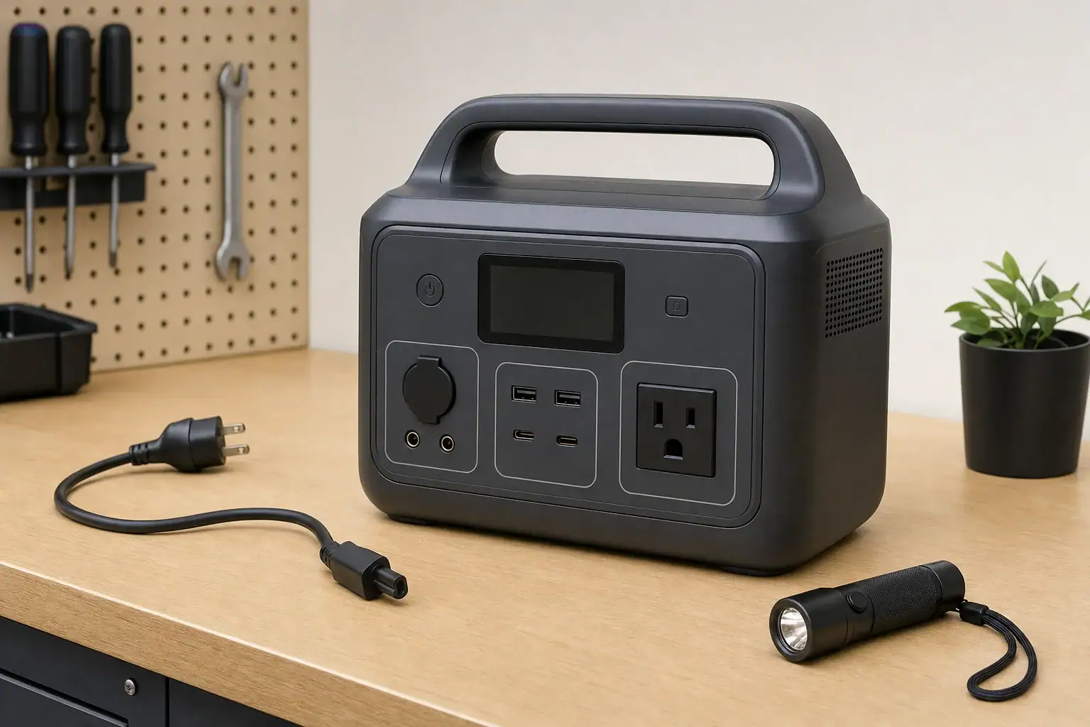
Portable power station with a blank screen on a workbench

If a portable power station screen is frozen or blank, disconnect its loads and charging cables, let the unit return to a safe room temperature, and perform the normal shutdown or restart described in its manual. Then reconnect only a manufacturer-approved charging source. A blank display may reflect sleep mode or an empty battery, but it can also indicate temperature protection, a software lockup, or a display failure.

Do not assume the unit is off merely because the screen is dark. If its outlets still work, turn them off using the normal controls and avoid powering critical equipment until battery level, warnings, and operating status are visible again.

Start with these checks

  1. Disconnect everything. Remove appliances from the AC, DC, and USB outputs. Disconnect solar panels, vehicle charging cables, expansion batteries, and AC charging equipment.
  2. Inspect the unit without opening it. Stop using it if you notice swelling, leaking, smoke, unusual odor, crackling, severe impact damage, water intrusion, or excessive heat. Move away from the unit and follow the manufacturer’s emergency guidance.
  3. Try the normal wake control. Briefly press the main power or display button. Some screens turn off after a period of inactivity even while the station remains on.
  4. Perform a normal power cycle. Use the shutdown and restart procedure in the manual. Button combinations and required hold times vary, so do not guess at a reset sequence.
  5. Allow temperature recovery. If the station was in a hot vehicle, direct sun, or freezing conditions, switch it off and let it gradually reach a dry indoor temperature within its specified operating range. Do not charge a battery that is excessively hot or cold.
  6. Connect an approved charger. Use the supplied charger or another source the manufacturer identifies as compatible. Confirm that the wall outlet works, then leave the station connected for the minimum wake-up period specified in its instructions.

If the screen is blank

Look for other signs of power, such as button illumination, cooling-fan activity, app connectivity, charging indicators, or output status lights. These observations help separate a display problem from a station that is completely unresponsive.

Blank screen, but the station otherwise responds

The display may be asleep, set to very low brightness, or malfunctioning. If the model supports an official app, check whether it reports display brightness, screen timeout, battery level, temperature warnings, or firmware status. Treat app readings cautiously if they stop updating.

Turn off all outputs when finished. Operating with no working display makes it harder to see overload, temperature, and low-battery warnings.

Blank screen and no response

A deeply discharged battery may need time on an approved charger before the controls wake. If there is still no response after the manufacturer’s stated charging period, try another known-good compatible charging method only if the manual permits it. For example, a model that accepts both its supplied AC charger and specified USB-C charging may allow one source to help identify a failed adapter or input port.

Do not substitute a charger based only on connector fit. Voltage, current, polarity, communication protocols, and input limits must all be compatible.

If the screen is frozen

A frozen screen may continue showing an old battery percentage, wattage reading, or warning even though conditions have changed. Disconnect all loads first so that an outdated display cannot hide a falling battery level or overload.

After a normal power cycle, reconnect the charger with no loads attached. If the screen works again, add devices one at a time. A particular cable, accessory, high-starting-power appliance, or overloaded output may be triggering the problem.

Appliances with motors or compressors can briefly draw more than their normal running watts. That surge can exceed the station’s surge rating even when the appliance’s continuous wattage is below the station’s continuous output rating. Both ratings vary by model, and a display lockup during such an event should not be treated as proof that the load is compatible.

Use reset and firmware options carefully

Some power stations provide separate soft-restart, system-reset, battery-management reset, and factory-reset procedures. These are not interchangeable. A factory reset may erase settings, while an undocumented button combination may have unintended effects. Use only the exact procedure in the current manufacturer instructions for the model and hardware revision.

If an official firmware update specifically addresses display behavior, follow the manufacturer’s prerequisites. The station may need a minimum charge level, stable app connection, or uninterrupted external power. Do not start an update while the unit is supplying a critical load.

A full discharge-and-recharge cycle is not a universal screen fix and adds battery wear. Perform battery-meter calibration only when the manufacturer recommends it for that model.

Record clues before requesting service

  • Whether the screen is fully dark, flickering, dim, or stuck on one image
  • The displayed battery percentage or error code, preferably photographed
  • Which inputs and outputs were connected when the problem began
  • Approximate ambient temperature and whether the unit was recently moved from heat or cold
  • Whether buttons, fans, lights, outputs, or an official app still respond
  • Model, serial number, firmware version, and purchase information

When to stop troubleshooting

Contact the manufacturer or an authorized service provider if the screen remains blank or repeatedly freezes after an approved restart and charging attempt. Service is also appropriate if the problem returns under light loads, the reported charge changes erratically, controls stop responding, or the enclosure shows damage.

Do not open the power station, probe internal components, bypass protection systems, or attempt battery repairs. Until the display and warning functions are reliable, do not depend on the station for medical equipment or other critical backup needs.

How to Clean Portable Solar Panels Without Damage

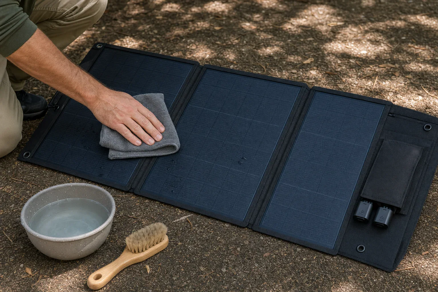
Person gently cleaning a foldable portable solar panel with a damp microfiber cloth

To clean a portable solar panel, disconnect it, let it cool, remove loose dust with a soft brush, and wipe the surface gently with a damp microfiber cloth. Clean water is usually enough. Keep connectors, junction boxes, seams, and fabric backing as dry as possible, then let the panel dry completely before reconnecting or folding it for storage.

Avoid pressure washers, abrasive pads, stiff brushes, solvents, glass cleaners, and scraping tools. Portable panels vary in surface coating and water resistance, so follow the panel manufacturer’s current care instructions whenever they differ from this general guidance.

What you need

  • A clean, soft microfiber cloth
  • A very soft brush for loose dust and grit
  • Clean, lukewarm water
  • Distilled or deionized water for a final wipe if tap water leaves mineral spots
  • A small amount of mild soap only if the manufacturer permits it

Use separate clean cloths for washing and drying. A cloth that contains sand, metal particles, or dried dirt can scratch a panel’s protective surface.

Safe cleaning steps

  1. Check the care instructions. Confirm whether the panel may be wiped with water and whether any cleaners are prohibited. A weather-resistant panel is not necessarily suitable for spraying, soaking, or submersion.
  2. Disconnect the panel. Follow the manufacturer’s shutdown and disconnection sequence for the panel, power station, or charge controller. Do not allow moisture into unplugged connectors, and do not clean damaged cables or connectors while they are connected.
  3. Move it to a stable, shaded surface. Let the panel cool before cleaning. Applying cool water to a hot surface can create thermal stress, and water may evaporate quickly enough to leave spots.
  4. Remove loose grit first. Tilt the panel slightly and use a soft brush with light strokes so particles fall away. Do not grind sand or dried mud into the surface with a wet cloth.
  5. Wipe gently with clean water. Dampen—not saturate—a microfiber cloth and wipe in light, straight passes. Support foldable panels so hinges and active sections are not bent backward or pressed against sharp objects.
  6. Treat stuck-on residue patiently. Hold a damp cloth over bird droppings, sap, or dried mud for a few minutes to soften it, then wipe gently. Do not scrape with a blade, fingernail, or hard plastic edge. If water does not work, use only a cleaner specifically allowed by the manufacturer.
  7. Dry and inspect. Wipe away remaining water with a clean cloth and allow the panel, seams, cable ends, and connectors to air-dry in the shade. Reconnect or store it only when fully dry.

Products and methods to avoid

  • Pressure washers and strong hose jets: Water can be forced through edge seals, stitching, junction boxes, or connector housings.
  • Abrasive sponges, powders, or stiff brushes: These may scratch glass or polymer coatings and create areas that hold more dirt.
  • Household glass cleaner: Ammonia, alcohol, fragrance, or other additives may be incompatible with anti-reflective coatings, plastics, adhesives, or printed surfaces.
  • Solvents, degreasers, bleach, and vinegar: Do not use them unless the panel manufacturer explicitly approves the specific product and dilution.
  • Compressed air at close range: A concentrated jet can push debris across the surface or force contamination into seams.
  • Walking, kneeling, or placing weight on the panel: Cells and internal conductors can crack even when the outer layer looks intact.
  • Cleaning while the panel is hot or electrically connected: Disconnect it and allow it to cool first.

Special care for foldable and flexible panels

Foldable portable panels often combine laminated solar sections with fabric, stitched edges, magnets, handles, and external pockets. These components may have different water resistance from the active panel face. Use a damp cloth rather than spraying the entire assembly, and prevent water from collecting in folds or cable pockets.

Do not sharply crease a flexible panel or bend it beyond the manufacturer’s stated limit. When drying or wiping, support the full panel rather than lifting one active section by a corner. Wait until the backing and hinges are dry before folding it, because trapped moisture can encourage odors, staining, or corrosion around hardware.

How often to clean

Clean when the panel is visibly dusty, spotted, or covered with pollen, mud, salt residue, leaves, or droppings. There is no universal schedule: a panel used occasionally on grass may need little attention, while one exposed to windblown sand or coastal spray may need a gentle wipe after each trip.

A lower charging rate can also prompt an inspection, but output alone does not prove the panel is dirty. Clouds, partial shade, panel angle, cell temperature, cable condition, and the receiving device’s charge limits can all change power production. Compare performance only under reasonably similar sunlight and setup conditions.

Inspect before reconnecting

After cleaning, look for cracked surfaces, peeling laminate, cloudy areas beneath the outer layer, loose seams, exposed conductors, damaged cable insulation, or scorched and deformed connectors. Stop using the panel if damage could expose electrical parts or allow water inside, and consult the manufacturer’s current service guidance rather than attempting to open or reseal the panel yourself.

Why Won’t My Portable Power Station Charge From the Wall?

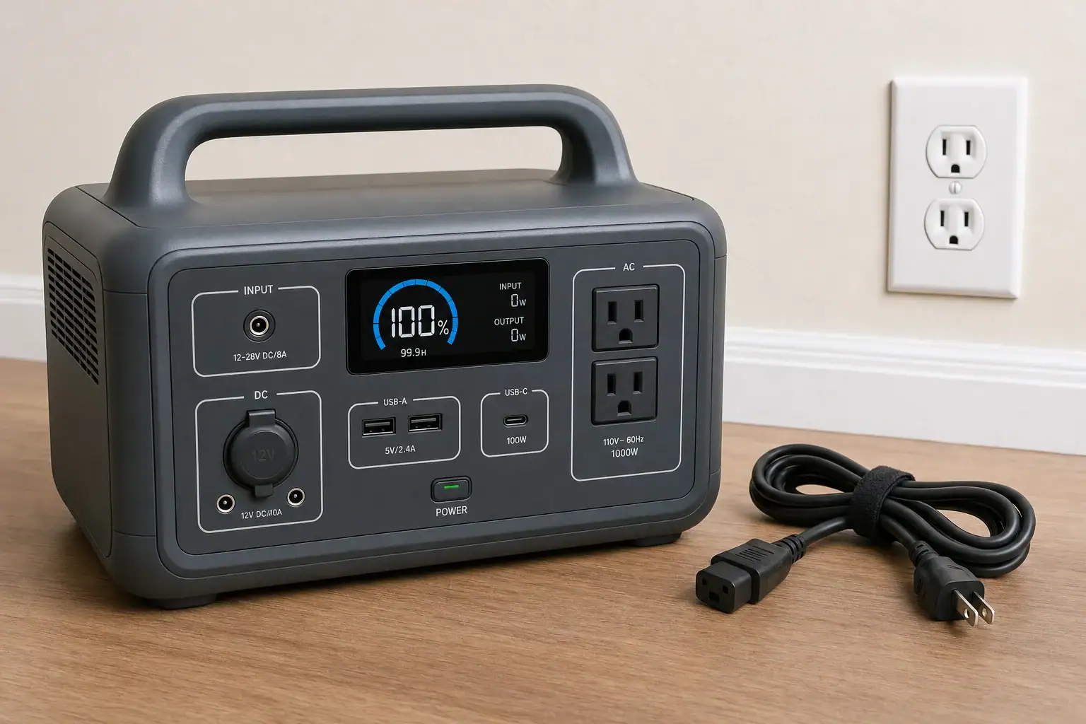
Portable power station and AC charging cord beside a wall outlet

If your portable power station will not charge from a wall outlet, the most likely causes are a dead outlet, a loose or incompatible charging cord, a charging limit or schedule, an out-of-range battery temperature, connected loads consuming the incoming power, or a fault in the AC charger. Start by disconnecting all loads, checking the display for warnings, and connecting the manufacturer-specified charging equipment directly to a known-working outlet.

Stop troubleshooting if the station, plug, cord, or external adapter becomes unusually hot, smells burnt, sparks, swells, or shows visible damage. Unplug it if that can be done safely, move away from the equipment, and follow the manufacturer’s current safety guidance. Do not open the unit, bypass its protection system, or repeatedly reset a breaker or ground-fault outlet that trips.

Use This Troubleshooting Order

  1. Disconnect everything from the power station’s outputs. Turn off its AC inverter, USB ports, and DC outputs where the controls allow. A connected appliance can consume most or all of the incoming charging power.
  2. Check the screen or status lights. Look for an input-power reading, charging icon, temperature warning, scheduled-charging message, battery limit, or fault code. Consult the model’s manual for the exact meaning of any code.
  3. Reconnect the AC charging equipment firmly. Confirm that both ends are fully seated. If the model uses an external power brick, check the connection between the wall cord, brick, and station.
  4. Try a known-working wall outlet. Connect directly rather than through a questionable power strip, timer, travel adapter, or extension cord. Do not use an outlet that is loose, discolored, wet, cracked, or unusually warm.
  5. Verify the cord or adapter. Use the manufacturer-specified charger and a cord rated for the equipment and local electrical supply. A connector that physically fits is not proof of compatible voltage, polarity, current, or wiring.
  6. Check settings and temperature. Disable an unintended charging schedule and confirm that the battery has not reached its configured charge limit. Let a very hot or cold unit return naturally to the charging-temperature range stated in its manual.
  7. Restart it only as directed. A normal shutdown and restart may clear a temporary status error, but use the documented procedure for your model. Do not attempt an undocumented reset, battery jump, or protective-device bypass.

Confirm That the Wall Outlet Is Actually Supplying Power

A known-working lamp or other simple household device can show whether an outlet has power, but it cannot prove that the circuit will support a power station’s full charging demand. A station may begin charging and then stop if the outlet is worn, the circuit voltage drops under load, or another appliance shares the circuit.

If a ground-fault outlet or circuit breaker trips when charging begins, disconnect the station. Do not defeat grounding, hold a reset mechanism in place, or keep retrying. Follow the outlet or breaker manufacturer’s instructions and have the circuit evaluated by a qualified electrician when appropriate. If the circuit works normally with other substantial loads but trips only with the power station, contact the station manufacturer.

Inspect the Charging Cord and External Adapter

Some power stations contain the AC charger internally and use a detachable mains cord. Others require an external adapter. In either case, inspect accessible parts without disassembling them. Look for bent pins, cuts, crushed insulation, damaged connectors, looseness, or debris around the inlet.

An indicator light on an external adapter can offer a clue, but it is not a complete diagnosis. A dark light may indicate a dead outlet, cord failure, or adapter failure. A lit adapter may still be unable to provide the correct output under load.

Do not substitute a generic adapter based only on connector size. Replacement equipment should match the model requirements for input voltage and frequency, adapter output voltage, polarity, maximum current, connector type, and grounding or insulation design. Check the power station label, original adapter label, manual, and current manufacturer guidance.

Check Charging Limits, Schedules, and Modes

A station can appear healthy while intentionally refusing a wall charge. Depending on the model, settings that affect AC charging may include:

  • A maximum state-of-charge limit, such as a user-selected storage level
  • A scheduled charging window or time-of-use setting
  • A quiet or slow charging mode
  • An AC input-power limit
  • A storage, transport, or battery-preservation mode
  • Remote controls in a companion application

If the battery is already at the configured limit, zero charging power may be normal. Settings names and behavior vary, so confirm them in the instructions for the exact model rather than assuming a general reset will restore charging.

Account for Temperature Protection

Lithium-based batteries commonly restrict charging when their cells are too cold or too hot. The display may remain on and the outputs may still work even though charging is temporarily blocked. The permitted charging range varies by battery chemistry, model, and sensor location.

Move the station to a dry, ventilated environment within the range specified by its manufacturer and allow time for the internal battery temperature to stabilize. Do not heat it with a space heater, hair dryer, heating pad, or open flame, and do not place it in a refrigerator or freezer.

Make Sure Connected Loads Are Not Hiding the Charge

When a power station supports simultaneous charging and output, connected devices can make the battery percentage rise very slowly or not at all. The approximate power available to the battery is:

Net battery charging power ≈ wall input power − output loads − internal conversion losses and operating overhead

For example, if the display reports 300 watts of AC input while connected equipment uses 220 watts, less than 80 watts may remain for the battery after conversion losses and the station’s own consumption. Displayed input and output values may also be measured at different points in the conversion path, so they should be treated as estimates.

A rough ideal charging-time estimate is battery energy in watt-hours divided by net charging power in watts. A 600-watt-hour refill at a net 100 watts would be at least six hours in the ideal calculation. Actual charging usually takes longer because power may taper near full charge, the battery may not use its entire labeled capacity, and displays round their readings.

Disconnecting all output devices is therefore an important diagnostic step. Never connect the station’s AC output back into its own charging input.

Interpret What the Station Is Doing

No display, charging icon, or input reading

Check the outlet, cord, adapter, and physical connection first. If the battery was left empty for an extended period, its protection system may require the manufacturer’s documented recovery procedure. Do not try to force-charge or jump the battery.

Input power appears, but the percentage does not rise

Disconnect all loads and check the configured charge limit. The displayed percentage can also pause while the battery-management system estimates state of charge, especially near the top or bottom of the range. Persistent behavior may require manufacturer diagnosis.

Charging starts and then stops

Look for temperature warnings, an unstable connection, a scheduled-charging rule, or a reported input fault. If the plug or adapter becomes hot, disconnect it and stop using the damaged or suspect component.

Other charging sources work, but wall charging does not

If an approved vehicle or solar input charges the station normally while AC charging consistently fails, the battery itself may still be functional. The problem is more likely in the wall cord, external adapter, AC input connection, settings, or internal AC charging circuit. This is useful information to provide to the manufacturer, but it does not identify which component is defective.

When to Request Service

Contact the manufacturer or an authorized service provider if known-good outlets and the correct charging equipment do not solve the problem, or if the unit reports a recurring fault code. Record the model and serial information, displayed error, battery percentage, approximate ambient temperature, input-power reading, and whether the same failure occurs with all loads disconnected.

Do not open the enclosure or attempt battery, fuse, charger-board, or mains-voltage repairs. Internal battery energy and AC circuitry can remain hazardous even when the unit appears off.

The fastest safe diagnosis is to remove connected loads, verify a sound outlet, confirm the exact cord or adapter, and review charging limits and temperature warnings. If wall input still remains at zero or repeatedly faults, stop troubleshooting at the user-serviceable level and seek model-specific support.