Solar extension cables start to matter when their length and thickness cause enough voltage drop that your portable power station charges slower or stops charging altogether. Long cable runs, undersized wire gauge, and low solar input voltage all work together to create power loss, wasted watts, and confusing charging behavior.
Users often search for terms like “solar cable length limit,” “voltage drop calculator,” “wire gauge for 12V solar,” “portable power station solar input,” or “why my panels only show half watts.” All of these issues usually trace back to resistance in the cables between your solar panel and your power station. Understanding how voltage drop works helps you choose the right cable gauge, length, and connectors so you can get closer to the rated watts from your panels in real-world conditions.
When Solar Extension Cable Length Actually Matters
Solar extension cables are the wires that connect your portable solar panels to your portable power station or solar generator input. They let you put panels in the sun while keeping your power station in the shade, inside a tent, or in a vehicle. The longer these cables are, the more electrical resistance they add to the circuit.
Voltage drop is the reduction in voltage that occurs as electricity flows through a cable with resistance. In solar setups, this means the voltage at the power station input is lower than the voltage at the panel terminals. If the drop is small, you barely notice it. If it is large, your portable power station may charge slowly, fall out of its maximum power point tracking (MPPT) range, or not recognize the solar input at all.
This matters most for portable systems because they often use relatively low-voltage solar inputs (commonly 12–48 V) and modest panel wattages. Even a few volts of loss can represent a big percentage of the total, cutting your effective charging watts by 10–30% or more. When you stretch panels far from your campsite or vehicle with long extension cables, voltage drop becomes a key design constraint instead of a minor detail.
Knowing when cable length starts to matter helps you decide whether you need thicker wire (lower AWG number), higher-voltage panel configurations, shorter runs, or a different layout to keep your system efficient and reliable.
How Voltage Drop Works in Solar Extension Cables
Voltage drop in solar extension cables comes from basic electrical principles: every real-world wire has resistance, and resistance causes a voltage loss when current flows. The main factors are cable length, wire gauge (AWG), current (amps), and system voltage.
1. Cable length
Resistance increases with length. Doubling the length of a cable roughly doubles its resistance, which doubles the voltage drop at the same current. In solar, you must consider the full round-trip distance: from panel to power station and back through the return conductor. A 30 ft extension is effectively 60 ft of conductor.
2. Wire gauge (AWG)
American Wire Gauge (AWG) numbers decrease as the wire gets thicker. Thicker wire (lower AWG number, like 10 AWG) has less resistance per foot than thinner wire (higher AWG number, like 16 AWG). For the same length and current, 10 AWG will have much less voltage drop than 16 AWG.
3. Current (amps)
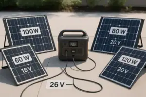
Voltage drop (V) is proportional to current (I). Higher current means more drop for the same cable. Solar panel current depends on panel wattage and operating voltage. For example, a 200 W panel at 20 V outputs about 10 A, while a 200 W array at 40 V outputs about 5 A. Higher-voltage strings move the same power with less current and less voltage drop.
4. System voltage (percentage drop)
What really matters is percentage drop, not just volts lost. A 1.5 V drop on a 12 V system is over 12%, but on a 48 V system it is only about 3%. Portable power stations with higher-voltage solar inputs are more tolerant of long cables because the same absolute voltage drop represents a smaller fraction of the total.
In practice, many users aim to keep voltage drop under about 3–5% between the solar panel and the power station input for efficient charging. Beyond that, you may see noticeably reduced watts or problems staying in the MPPT input window.
| Panel Power | Approx. Voltage | Approx. Current | Typical Use Case |
|---|---|---|---|
| 100 W | 18–21 V | 4.5–6 A | Small portable panel, short cable runs |
| 200 W | 18–21 V | 9–11 A | Two 100 W panels in parallel |
| 200 W | 36–42 V | 4.5–6 A | Two 100 W panels in series |
| 400 W | 36–42 V | 9–11 A | Four 100 W panels, series-parallel |
MPPT Inputs and Voltage Drop Sensitivity
Most modern portable power stations use MPPT (maximum power point tracking) charge controllers on their solar inputs. These controllers expect solar voltage to stay within a certain operating window, such as 12–60 V or 20–55 V, depending on the model.
When voltage drop pulls the actual voltage at the input below the minimum threshold, the MPPT either derates the power or stops tracking entirely. Similarly, if the cable resistance is high, changes in sunlight can cause the operating point to jump around more, leading to unstable or reduced charging.
Because MPPT controllers constantly adjust to find the best combination of voltage and current, they will “see” the cable resistance as part of the panel behavior. Excessive resistance makes the controller think the panel has worse performance than it really does, so it settles on a lower power point than the panel could deliver with a better cable.
Real-World Examples of Cable Length and Voltage Drop
Translating theory into real-world behavior helps you decide when to upgrade cables or reconfigure your solar setup. Here are illustrative scenarios that mirror common portable power station use cases.
Example 1: Single 100 W panel with a long, thin cable
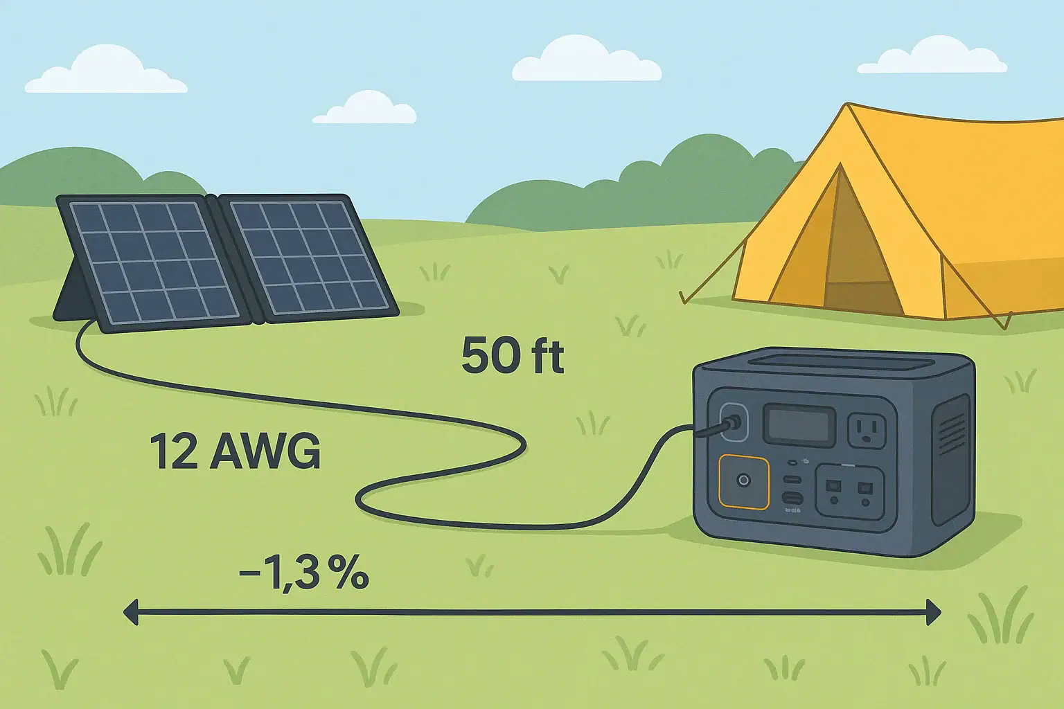
Imagine a 100 W folding panel rated around 18 V at maximum power, producing about 5.5 A in full sun. You use a 50 ft extension cable made from 16 AWG wire to reach from the sunny area to your shaded campsite.
At this length and gauge, voltage drop can easily reach several volts. If you lose, for example, 2 V out of 18 V, that is over 11% loss. Your portable power station might only see 85–90 W at best, and on hazy days the effective power could drop even further as the MPPT struggles with the extra resistance.
Example 2: Two 100 W panels in parallel on a long run
Now consider two 100 W panels wired in parallel, still around 18–20 V but now up to 10–11 A. You keep the same 50 ft, 16 AWG extension. Current has roughly doubled, so voltage drop doubles too. If you were losing 2 V before, you might now lose 4 V or more in bright sun.
Dropping from 20 V at the panels to 16 V at the power station is a 20% reduction. The controller may still charge, but your effective wattage could fall from 200 W potential to 150 W or less, even in perfect sunlight.
Example 3: Two 100 W panels in series with a thicker cable
Instead, suppose you wire the same two 100 W panels in series, giving around 36–40 V at about 5–6 A. You also upgrade to a 10 AWG extension cable of the same 50 ft length.
The current is now about half of the parallel case, and the wire is thicker with lower resistance per foot. Voltage drop might shrink to something like 1–1.5 V. Losing 1.5 V out of 38 V is only about 4%. Your portable power station might see 190+ W at the input, much closer to the panels’ rating under good sun.
Example 4: Very long runs in low-voltage systems
If you run a 12 V nominal panel (or low-voltage array) through 75–100 ft of thin cable, the voltage drop can be large enough that the power station’s solar input never reaches its minimum operating voltage. In this case, the unit may show “no input,” flicker between charging and not charging, or cap out at very low watts even in midday sun.
These examples show that cable length starts to matter once you combine low voltage, high current, and long runs. For portable systems, that often means anything beyond about 25–30 ft of cable deserves a closer look at wire gauge and panel configuration.
Common Mistakes and Troubleshooting Voltage Drop Issues
Many solar charging problems that look like “bad panels” or “faulty power station” are actually wiring and voltage drop issues. Recognizing the symptoms can save time and frustration.
Mistake 1: Using very thin, generic extension wire
Household extension cords or cheap, thin DC cables are often 16–18 AWG or smaller. When used for solar runs of 30–50 ft at 8–12 A, they introduce significant resistance. Symptoms include lower-than-expected watts, cables that feel warm to the touch, or voltage readings that drop sharply when connected.
Mistake 2: Extending on the low-voltage side of the system only
Some users run long cables from the panels to the power station while keeping the panels in a low-voltage parallel configuration. This maximizes current and therefore voltage drop. In many cases, it is better to wire panels in series (within the power station’s voltage limits) to increase voltage and decrease current over the long run.
Mistake 3: Ignoring connector contact resistance
Each extra connector pair adds a little resistance. Loose, corroded, or low-quality connectors add more. A chain of multiple adapters, splitters, and extensions can create enough added resistance and heat that voltage drop and power loss become noticeable, even if the cable gauge seems adequate on paper.
Mistake 4: Misreading wattage on cloudy or hot days
Solar panels rarely produce their full rated watts except under ideal test conditions. On a hot roof or in hazy conditions, 60–80% of rated output is common even with perfect wiring. Users sometimes blame cables for low output when the main cause is reduced irradiance or high panel temperature. However, if you see a further 10–20% drop when you add the extension cable, voltage drop may be contributing.
Troubleshooting cues
- If the power station reads normal watts with a short factory cable but drops significantly with the extension, suspect voltage drop.
- If cables or connectors feel unusually warm under load, current is high for the gauge and length.
- If the solar input flickers on and off when clouds pass or devices turn on, the voltage may be hovering near the MPPT minimum due to cable losses.
- If a multimeter shows much lower voltage at the power station end of the cable than at the panel, especially under load, the cable is too long, too thin, or both.
In these cases, shortening the run, using a thicker gauge, or reconfiguring panels in series often restores stable, higher charging power.
Safety Basics for Long Solar Cable Runs
While portable solar systems are generally low-risk compared to household AC wiring, long extension cables still deserve basic safety attention. Voltage drop and heat are linked: excessive current in undersized wires causes temperature rise, which can damage insulation and connectors over time.
Match wire gauge to current and length
Choose cable with an appropriate AWG rating for the maximum current you expect and the total run length. Thicker wire not only reduces voltage drop but also runs cooler. Avoid pushing thin cable near its ampacity limit for long periods in hot environments or direct sun.
Use cables rated for outdoor and solar use
Outdoor-rated insulation resists UV, moisture, and abrasion better than generic indoor cable. Purpose-built solar cable is typically double-insulated and more rugged. This reduces the risk of cracks, shorts, or exposed conductors over time, especially when cables are dragged across rough surfaces or pinched in doors or windows.
Protect connections from strain and damage
Long cable runs are prone to being tripped over, tugged, or snagged. Strain on connectors can loosen contacts, increasing resistance and heat. Use gentle bends, avoid tight kinks, and support cables where they cross walkways or sharp edges. Do not pull on cables to move panels or the power station.
Avoid DIY modifications without proper knowledge
Cutting, splicing, or re-terminating solar cables without the right tools and techniques can create poor connections, reversed polarity, or exposed conductors. If you need custom lengths or unusual configurations, consider pre-made cables from reputable sources or consult a qualified electrician for guidance.
Respect system voltage and series configurations
When wiring panels in series to reduce current and voltage drop, always verify that the combined open-circuit voltage stays below your portable power station’s maximum input rating. Exceeding this limit can damage the input circuitry. If you are unsure, seek advice from a knowledgeable professional and follow the device’s documentation.
Maintaining and Storing Solar Extension Cables
Good maintenance practices help your solar extension cables stay flexible, safe, and low-resistance over years of use with portable power stations. Poorly stored or neglected cables are more likely to develop damage that increases voltage drop or creates safety issues.
Inspect regularly for wear and corrosion
Before and after trips, look along the entire length of each cable for cuts, abrasions, flattened spots, or exposed conductors. Check connectors for discoloration, pitting, or greenish corrosion. Any visible damage or corrosion increases resistance and can lead to hot spots under load.
Keep connectors clean and dry
Moisture, dust, and grit inside connectors interfere with good contact. When not in use, cap connectors if possible and store cables in a dry place. If connectors get dirty, gently clean them with a soft brush or cloth and allow them to dry completely before reconnecting.
Coil cables loosely to avoid kinks
Sharp bends and tight kinks can break conductor strands inside the insulation, increasing resistance at those points. Coil cables into large, relaxed loops and avoid wrapping them tightly around small objects. Do not tie knots in cables or force them into cramped storage spaces.
Avoid prolonged exposure to harsh conditions
Leaving cables permanently in direct sun, standing water, or areas with heavy foot traffic accelerates wear. For portable setups, it is usually best to deploy cables only when needed and store them when not in use. This preserves insulation, reduces tripping hazards, and keeps connectors from corroding.
Label lengths and gauges
If you own multiple cables with different lengths and gauges, label them clearly. Knowing which cable is 25 ft of 10 AWG versus 50 ft of 14 AWG makes it easier to choose the right one for a given solar setup and avoid unintentional voltage drop from using the wrong cable.
| Practice | Benefit | How It Helps Voltage Drop |
|---|---|---|
| Regular inspection | Catches damage early | Prevents hidden high-resistance spots |
| Clean connectors | Reliable contact | Reduces extra contact resistance |
| Proper coiling | Longer cable life | Avoids internal strand breakage |
| Dry storage | Less corrosion | Maintains low-resistance connections |
Related guides: Why Won’t It Charge From Solar? A Troubleshooting Checklist • Solar Safety Basics: Cables, Heat, and Preventing Connector Melt • How to Read Solar Panel Specs for Power Stations: Voc, Vmp, Imp, and Why It Matters
Practical Takeaways and Specs to Look For
For portable power station users, the main takeaway is that solar extension cables are not just simple accessories. Their length, gauge, and quality directly affect how many watts actually reach your battery. Once runs exceed roughly 25–30 ft, especially at 12–24 V and 8–12 A, cable selection can easily make a 10–30% difference in charging performance.
To keep voltage drop under control, think in terms of both absolute voltage loss and percentage loss. Use thicker wire for longer runs, consider series panel wiring within your power station’s safe voltage range, and minimize unnecessary connectors and adapters. Pay attention to heat, visible wear, and unstable charging behavior as cues that your cables may be undersized or degraded.
When planning or upgrading your solar cabling, it helps to have a simple rule of thumb: for every increase in cable length or current, compensate with a lower AWG (thicker wire) or higher system voltage. This mindset keeps your portable system efficient without needing complex calculations in the field.
Specs to look for
- Wire gauge (AWG) – Look for 10–12 AWG for 20–50 ft runs at 8–12 A; thicker (lower AWG) for higher currents or longer distances. Thicker wire reduces resistance and voltage drop.
- Cable length – Aim to keep individual runs under 25–30 ft when using 14–16 AWG; longer runs should use thicker wire. Shorter, properly sized cables keep losses in the 3–5% range.
- Voltage rating – Select cable rated comfortably above your array’s open-circuit voltage (for example, 600 V DC rating for typical portable setups). Adequate voltage rating ensures insulation safety margin.
- Current rating (amps) – Choose cables with continuous amp ratings at least 25–50% higher than your expected solar current (e.g., 15–20 A rating for 10–12 A use). Extra headroom keeps cables cooler and more efficient.
- Insulation type and outdoor rating – Look for UV-resistant, outdoor or solar-rated insulation. Durable jackets resist cracking and water ingress, preserving low resistance over time.
- Connector type and quality – Use connectors compatible with your panels and power station that lock securely and have firm contact. Solid connectors minimize contact resistance and intermittent drops in power.
- Operating temperature range – Prefer cables rated for both high heat and cold (for example, -40°F to 194°F). Stable performance across temperatures helps maintain consistent resistance and flexibility.
- Flexibility and strand count – Fine-stranded, flexible cable is easier to coil and less prone to internal damage from repeated bending. This helps avoid hidden high-resistance spots that increase voltage drop.
- Markings and polarity identification – Clear positive/negative markings and printed gauge/ratings reduce hookup errors. Correct polarity and known specs help maintain safe, efficient solar connections.
By paying attention to these specifications and understanding how voltage drop behaves, you can design solar cable runs that let your portable power station make the most of every watt your panels produce, even when the best sun is far from where you want to set up camp.
Frequently asked questions
What cable specs and features matter most to reduce voltage drop?
Key specs are wire gauge (lower AWG for thicker wire), total run length (round-trip), and the cable’s current rating. Also look for a high DC voltage rating, UV- and weather-resistant insulation, and quality connectors with low contact resistance. Together these reduce resistance, heat, and the chance of power loss over time.
How long can extension cables be before voltage drop becomes a real problem?
There is no single cutoff, but for low-voltage portable systems you should scrutinize runs beyond about 25–30 ft, especially at 12–24 V and currents around 8–12 A. The acceptable length depends on your AWG, system voltage, and current; higher-voltage or thicker cables tolerate much longer runs. If you see a greater than ~3–5% voltage drop, consider upgrading the cable or reconfiguring panels.
Is wiring panels in parallel for a long run a common mistake?
Yes—running panels in parallel keeps voltage low and current high, which increases voltage drop over long cables. When possible and within device limits, series wiring raises voltage and cuts current, reducing losses on long runs. Always verify the combined open-circuit voltage stays below your input’s maximum rating.
How can I tell if voltage drop is the reason my power station is charging poorly?
Compare input readings using the short factory cable versus the long extension: a notable drop in watts with the extension suggests voltage drop. Other signs include warm cables/connectors, the solar input flickering near clouds, and a multimeter showing much lower voltage at the device under load than at the panel. Those cues point to excessive resistance in the run or connections.
Are long solar cable runs a safety risk and how should I mitigate that?
Yes—undersized cables carrying high current can heat up, degrading insulation and increasing fire risk over time. Mitigate this by choosing appropriate AWG for the expected current and length, using outdoor-rated insulation, providing strain relief on connectors, and avoiding long runs with thin or damaged cables. Regular inspection and not exceeding cable ampacity help keep runs safe.
Can cheap household extension cords be used for solar extension runs?
Household extension cords are often too thin, not UV-rated, and lack proper DC connectors, which makes them a poor choice for solar runs. They can introduce significant voltage drop and may overheat under continuous DC loads. Use purpose‑built solar or heavy-duty outdoor-rated cable sized for your current and run length instead.
Recommended next:
- Are Portable Power Stations the Future of Backup Power?
- Portable Power Stations and Renewable Energy
- Solar Panel Series vs Parallel: Which Is Better for Charging a Power Station?
- How Many Solar Watts Do You Need to Fully Recharge in One Day?
- Overpaneling Explained: Can You Connect Bigger Solar Panels Than the Input Limit?
- Shading and Angle: How Placement Changes Solar Charging Speed
- More in Solar →
Related guides
Browse this topic →

- Beginner-friendly sizing, runtime & specs
- Solar & charging (MPPT, fast charging, cables)
- Batteries (LiFePO4, cycles, care & storage)
- Safety, cold-weather performance, real-world tips
More in Solar
See all →- How to Read Solar Panel Specs for Power Stations: Voc, Vmp, Imp, and Why It Matters
- Solar Safety Basics: Cables, Heat, and Preventing Connector Melt
- Balcony Solar + Power Station: A Practical Setup for Apartments
- MC4, Anderson, DC Barrel: Solar Connectors and Adapters Explained
- Shading and Angle: How Placement Changes Solar Charging Speed
Keep reading
About this site
Portable Energy Lab publishes practical, independent guides about portable power—clear sizing, safe use, and real-world expectations.
Affiliate disclosure
Some links on this site may be affiliate links. If you buy through these links, we may earn a small commission at no extra cost to you. This helps support our content. Learn more.