
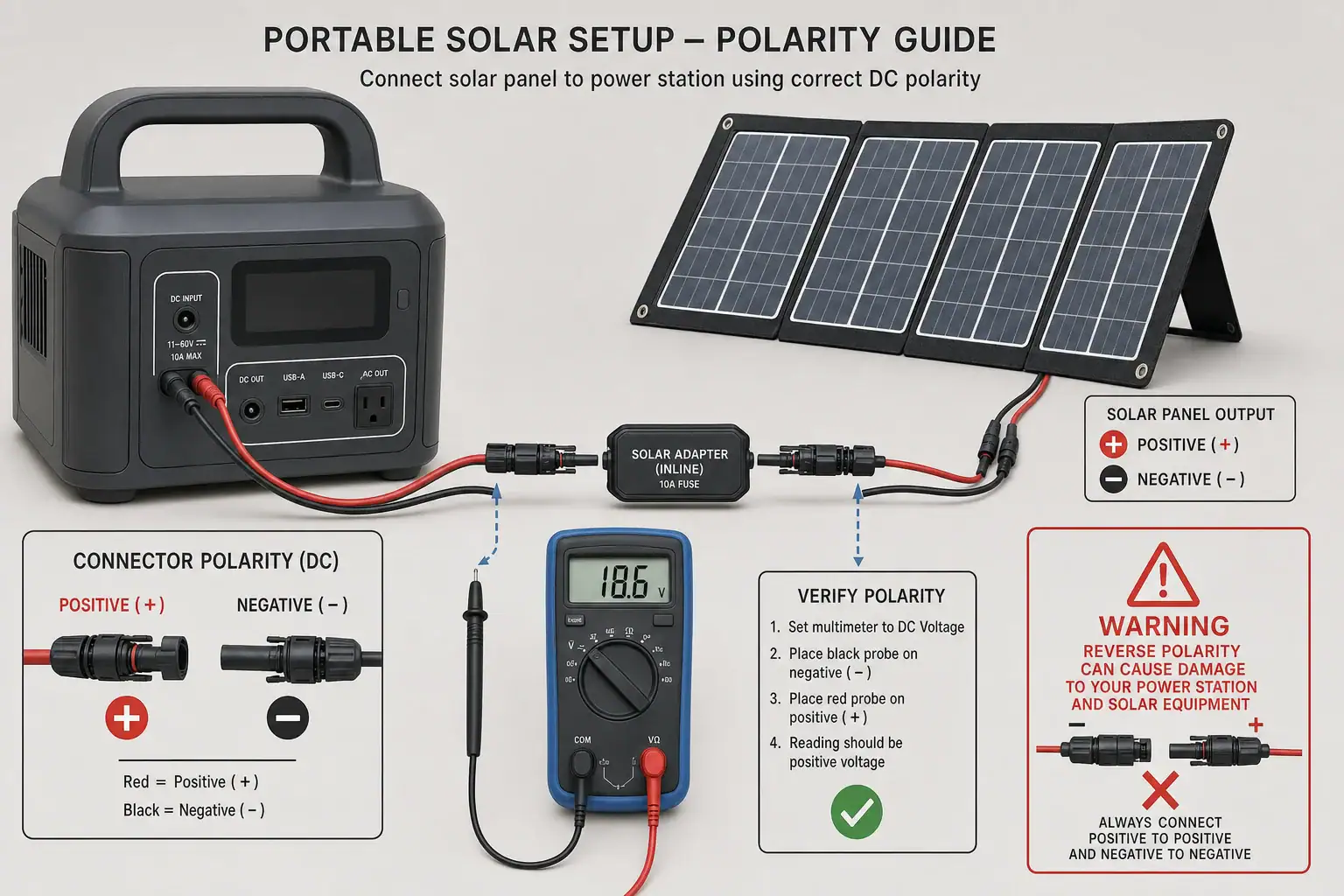
Reverse-polarity charging happens when a solar adapter sends positive voltage to the portable power station’s negative input contact and negative voltage to its positive contact. The safest solution is to verify the connector pinout, voltage range, open-circuit voltage, and input polarity before making the connection.
A cable can physically fit yet still be electrically incompatible. This is especially common with barrel plugs, coaxial DC adapters, extension cables, and solar connectors whose physical shape does not clearly indicate electrical polarity. A reverse-polarity connection may cause an input error, zero solar watts, repeated charging interruptions, or damage if adequate protection is absent.
Do not assume that matching connector dimensions guarantee compatibility. Check the polarity symbol on the power station, the solar panel output label, and the adapter documentation. If any marking is missing or contradictory, stop and verify the cable with appropriate test equipment or obtain help from a qualified technician.
1. What Solar Adapter Polarity Means and Why It Matters
Polarity describes which conductor carries positive voltage and which carries negative voltage in a direct-current circuit. Solar panels used with portable power stations produce DC electricity, so their positive and negative conductors must reach the corresponding contacts at the power station’s solar input.
On a common barrel connector, one electrical contact is the center pin or inner sleeve and the other is the outer sleeve. Many devices use a center-positive arrangement, but center-negative equipment also exists. Some power stations use multi-contact or aviation-style inputs with their own pin assignments. Similar-looking connectors can therefore have different wiring.
Solar connectors introduce another source of confusion: physical connector gender is not the same as electrical polarity. A connector housing that appears male may contain a female electrical contact, and cable assemblies can reverse the relationship. Positive and negative markings on the actual cable should take priority over assumptions based on shape.
Reverse polarity matters because internal charging electronics are designed for current to enter in one direction. A well-protected input may reject the connection without damage, but protection should not be treated as permission to experiment. Other possible results include a blown replaceable fuse in an approved cable, input protection shutdown, overheated wiring, arcing at a connector, or damage to the charging controller.
2. How Solar Polarity, Voltage, and Connectors Work Together
A compatible solar connection requires more than correct polarity. The panel or array must also remain within the power station’s accepted solar input voltage, current, and power ranges. Correct polarity with excessive open-circuit voltage can still damage an input, while incorrect polarity remains a problem even when voltage is otherwise acceptable.
Solar panel labels commonly list open-circuit voltage, abbreviated Voc, and operating voltage, often shown as Vmp. Voc is the higher voltage measured when the panel is not supplying a load. Because Voc can rise in cold weather, array planning should use the combined cold-condition open-circuit voltage rather than only the nominal or operating value.
Series-connected panels add voltage while current generally stays near the rating of one panel. Parallel-connected panels add available current while voltage remains near the rating of one panel. Parallel branches also require consistent polarity at every junction. One reversed branch can create a hazardous fault instead of simply reducing charging performance.
The adapter must preserve the electrical path from positive to positive and negative to negative. A polarity-reversing adapter intentionally swaps those conductors, while a straight-through adapter preserves them. These products can look nearly identical, so continuity or voltage testing may be necessary when reliable pinout information is unavailable.
| Item | Example marking | What to confirm |
|---|---|---|
| Power station input | 11–50 V DC, 10 A, 400 W | Panel voltage, current, and polarity fit the input specification |
| Solar panel | Voc 24.3 V, Vmp 20.4 V | Voc remains below the input maximum in expected temperatures |
| Barrel adapter | Center positive | Center and sleeve match the power station polarity symbol |
| Extension cable | Positive and negative labeled | The cable is straight-through and has adequate conductor size |
| Array connection | Two panels in series | Combined Voc is acceptable and end-to-end polarity is correct |
3. Real-World Reverse-Polarity Examples
A barrel plug that fits but does not charge
A user connects a solar panel through a barrel adapter that has the correct outer diameter. The power station shows zero input watts even in direct sunlight. The panel and station both operate normally with their original cables. Inspection reveals that the station expects center-positive polarity, while the adapter is wired center-negative. Physical fit did not establish electrical compatibility.
An extension cable that reverses the output
A panel charges the station correctly with a short factory-supplied lead. After an extension is added, charging stops and the input briefly reports an error. The extension uses matching connector shells but crosses the positive and negative conductors internally. Removing that extension restores operation, making the added cable the most likely fault location.
Confusing connector housing gender with polarity
A solar cable is assembled according to the appearance of its connector housings rather than the positive and negative markings. The completed adapter presents reversed polarity at the power station end. This mistake occurs because housing gender, metal-contact gender, and electrical polarity are separate characteristics.
A mixed array with one reversed branch
Two nominally similar panels are combined in parallel, but one branch is connected backward. Instead of doubling useful current, the branches oppose each other and may drive current through an unintended path. This is not a normal troubleshooting condition. The array should be disconnected and inspected by someone familiar with DC solar connections.
4. Common Mistakes and Troubleshooting Cues
The most common mistake is selecting an adapter solely by connector size. Barrel plugs may differ in outer diameter, inner diameter, pin depth, contact design, and polarity. A loose or partially fitting plug can also create intermittent charging that resembles a polarity problem.
Another frequent error is trusting wire color without verification. Red usually indicates positive and black usually indicates negative, but repaired, relabeled, or nonstandard cables may not follow that convention. Molded arrows and plus or minus symbols can also refer to connector alignment rather than electrical polarity.
Typical reverse-polarity cues include zero input power in strong sunlight, an immediate solar input fault, charging that begins only after changing adapters, or a protective cable fuse that opens repeatedly. However, these symptoms are not conclusive. Shade, low irradiance, excessive panel voltage, poor contact, damaged wiring, input current limits, and a disabled solar charging setting can produce similar behavior.
Troubleshoot by simplifying the system without modifying it. Disconnect the solar source, inspect labels and connector condition, and compare the station’s required pinout with the adapter’s documented pinout. Remove unnecessary extensions, splitters, and converters. If a known-compatible original cable works but an added adapter does not, the adapter or its connection is a strong suspect.
A digital multimeter can confirm DC voltage and polarity when used by a person familiar with its ratings and safe operation. A positive reading generally means the red probe is touching the positive contact relative to the black probe. A negative sign indicates the relationship is reversed. Avoid shorting closely spaced contacts with probe tips, and do not test exposed conductors in wet conditions. When connector identification or meter use is uncertain, use a qualified solar or electrical technician.
5. Safety Basics for Solar Charging Connections
Disconnect the solar panel before changing adapters or rearranging an array. Covering or turning a portable panel away from direct sunlight can reduce production, but it may not eliminate voltage. Treat panel leads as energized whenever the panel is exposed to light.
Never force a connector, hold a loose plug in position, or repeatedly reconnect a cable that produces sparks, heat, odor, discoloration, or fault messages. Stop using any adapter with cracked insulation, bent contacts, corrosion, melted plastic, or exposed copper. A damaged connector can introduce resistance and heating even when its polarity is correct.
Do not open a portable power station, alter its battery pack, bypass input protection, or replace a protective device with a higher-rated substitute. These actions can defeat safeguards and create fire or shock risks. Use only external cables and adapters with suitable voltage, current, temperature, and environmental ratings.
Keep connectors dry and supported so cable weight does not pull against the input port. Make connections with dry hands and place the power station in a ventilated location consistent with its operating instructions. If a permanent solar installation, building wiring, rooftop array, or grounded system is involved, consult a qualified electrician or solar professional rather than improvising an adapter.
6. Cable Maintenance, Inspection, and Storage
Label compatible adapters at both ends with their connector type and verified polarity. A simple center-positive, center-negative, positive, or negative marking can prevent mix-ups when several similar cables are stored together. Keep polarity-reversing adapters physically separated from straight-through adapters.
Before each use, inspect connectors for dirt, corrosion, looseness, bent contacts, and heat damage. Wipe dry, de-energized connector exteriors with a clean cloth. Do not insert metal tools, liquids, or abrasive material into contacts. Protective caps help keep dust and moisture away during transport and storage.
Coil cables loosely rather than folding them sharply near molded strain reliefs. Tight bends can break conductors internally while leaving the outer insulation intact. Store adapters in a dry location away from direct heat, heavy objects, and chemicals that could degrade insulation.
Recheck polarity after any cable replacement, field repair performed by a qualified person, or change to a panel array. Also confirm that combined array voltage remains within the station’s input range. An adapter that was correct for one panel configuration may not be appropriate for a different series or parallel arrangement.
| When | Check | Reason |
|---|---|---|
| Before each connection | Polarity labels, connector fit, and visible damage | Prevents reversed or poor-contact connections |
| After transport | Bent contacts and crushed cable sections | Travel can damage conductors and connector shells |
| After an input fault | Adapter pinout and panel open-circuit voltage | Separates polarity faults from voltage incompatibility |
| Seasonally | Corrosion, label readability, and cable flexibility | Finds gradual environmental deterioration |
| After changing the array | End-to-end polarity and combined Voc | Confirms the new configuration remains compatible |
Related guides:MC4, Anderson, DC Barrel: Solar Connectors and Adapters Explained • How to Read Solar Panel Specs for Power Stations: Voc, Vmp, Imp, and Why It Matters • Solar Extension Cables and Voltage Drop: When Cable Length Starts to Matter • Solar Safety Basics: Cables, Heat, and Preventing Connector Melt
7. Practical Takeaways and Specs to Look For
Correct solar adapter polarity means the panel’s positive output reaches the power station’s designated positive input contact and the negative output reaches its negative contact. Verify this relationship from reliable markings or test results rather than connector appearance. Polarity is only one part of compatibility; voltage, current, wattage, connector dimensions, and cable capacity must also match.
If charging stops immediately after an adapter or extension is added, disconnect the system and compare that component’s pinout with the station’s requirements. Do not use repeated trial-and-error connections as a diagnostic method. A reverse-polarity protection feature can reduce risk, but it does not make an incompatible cable acceptable.
Specs to look for
- Input polarity: Look for an explicit center-positive, center-negative, or numbered-pin diagram; it identifies the required electrical path and prevents assumptions based on connector shape.
- Solar input voltage range: A range such as 12–50 V DC should accommodate operating voltage and cold-weather Voc; staying within range protects the charging controller.
- Maximum open-circuit voltage: Compare a limit such as 50 V with the array’s temperature-adjusted Voc; series panels can exceed the input limit even when nominal voltage seems acceptable.
- Input current limit: A rating such as 10 or 15 A shows how much current the station can accept; extra panel current may be clipped and requires appropriately rated connectors and cable.
- Maximum solar input power: Values such as 200–500 W indicate the charging capacity under suitable voltage conditions; panel wattage alone does not guarantee full input power.
- Connector dimensions and pinout: Look for exact barrel dimensions or a numbered contact map; similar-looking plugs may fit poorly or carry reversed polarity.
- Reverse-polarity protection: Look for documented electronic shutdown or replaceable inline protection; it may limit damage from an error but should not replace verification.
- Cable voltage and current rating: Choose ratings above the expected array output, such as 60 V DC and 15 A for a lower-powered portable setup; adequate capacity reduces overheating and voltage drop.
- Wire gauge and length: Shorter, heavier cable such as 12–14 AWG may reduce voltage drop compared with a long, thin extension; stable voltage supports more consistent charging.
Keep a verified, labeled adapter with the power station whenever possible. That small organizational step reduces the chance that a physically compatible but electrically reversed cable will be selected during travel, emergency use, or equipment changes.
Frequently asked questions
How can I tell whether a solar adapter is center-positive or center-negative?
Check the polarity symbol or pinout diagram on the adapter, power station, or product documentation. For a barrel connector, the diagram identifies whether the center contact or outer sleeve is positive. If the marking is unavailable or unclear, verify with a properly rated multimeter or seek qualified assistance.
What solar adapter specs and features should I check before connecting a panel?
Confirm the connector dimensions, electrical pinout, voltage rating, current rating, and cable capacity. Also compare the panel or array’s open-circuit voltage with the power station’s maximum solar input voltage. Documented reverse-polarity protection is useful, but it does not replace verifying compatibility.
Can a solar adapter fit correctly but still have the wrong polarity?
Yes. Connector shape and dimensions only indicate mechanical fit, not how the positive and negative conductors are wired. A physically compatible barrel plug, extension, or conversion cable can still reverse the electrical path.
Is it safe to test different solar adapters until one starts charging?
No. Repeatedly trying unverified adapters can expose the charging input, cable, or panel to reverse polarity or excessive voltage. Disconnect the solar source first and verify polarity, pinout, and voltage limits before making a connection.
Why does solar charging stop after I add an extension cable?
The extension may have a wiring fault, reversed polarity, poor connector contact, excessive voltage drop, or an insufficient current rating. Remove the extension and test with a known-compatible cable if possible. If charging resumes, inspect the extension’s pinout and condition before using it again.
Does reverse-polarity protection mean any solar cable is safe to use?
No. Protection may shut down the input or reduce damage from a wiring mistake, but its behavior and limits vary by device. An incompatible cable can still cause charging faults, blown protection components, overheating, or damage if protection is absent or exceeded.
Related guides
Browse this topic →
- Beginner-friendly sizing, runtime & specs
- Solar & charging (MPPT, fast charging, cables)
- Batteries (LiFePO4, cycles, care & storage)
- Safety, cold-weather performance, real-world tips
More in Solar
See all →- How to Clean Portable Solar Panels Without Damage
- Solar Charging on Cloudy Days: What Output Can a Portable Power Station Expect?
- How Many Portable Solar Panels Do You Need for a 1,000Wh Power Station?
- Portable Solar Panel Waterproof Ratings: What Rain, Dew, and Splash Resistance Mean
- Can You Charge a Portable Power Station Through a Window With Solar Panels?
Keep reading
About this site
Portable Energy Lab publishes practical, independent guides about portable power—clear sizing, safe use, and real-world expectations.
Affiliate disclosure
Some links on this site may be affiliate links. If you buy through these links, we may earn a small commission at no extra cost to you. This helps support our content. Read our affiliate disclosure.