
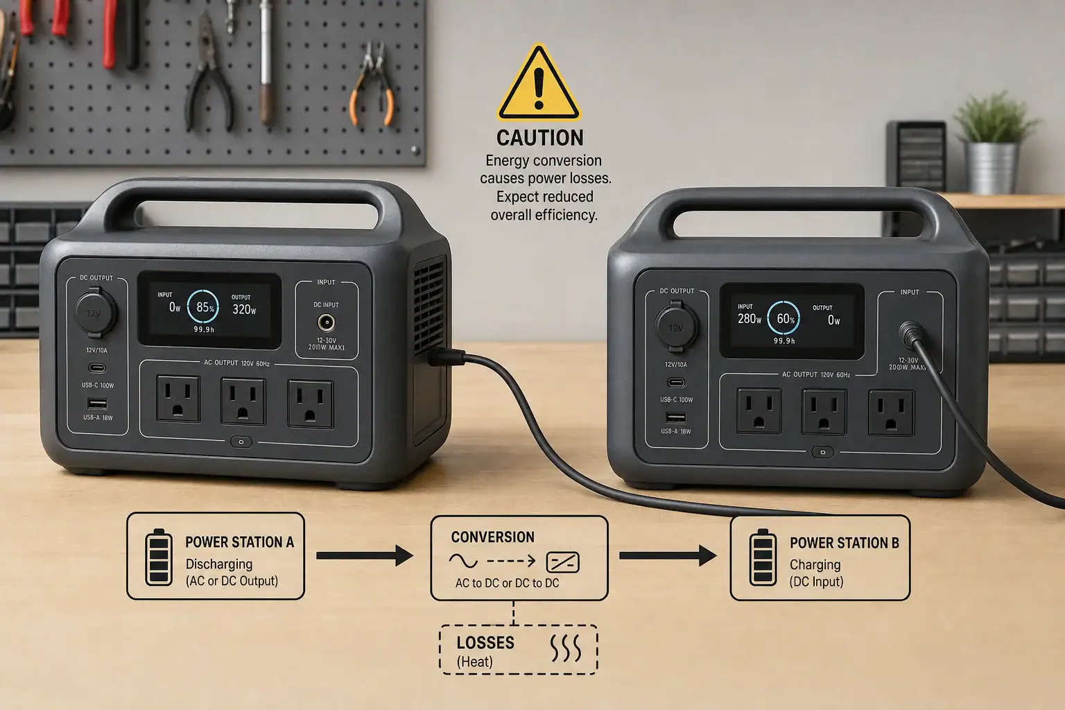
You can sometimes daisy-chain portable power stations by using one unit to charge another, but it is usually inefficient, limited, or unsupported. Portable power stations are not generally designed to have their battery outputs combined like ordinary battery cells. Differences in battery voltage, input limits, inverter ratings, charging protocols, and protection systems can prevent safe or useful operation.
The phrase “daisy-chain” may refer to several different arrangements: plugging one station’s AC charger into another station, feeding a DC output into a charging input, connecting batteries in series or parallel, or using an approved expansion battery. These methods are not equivalent. AC-to-AC chaining wastes energy through repeated conversion, while improvised DC connections can create overload, reverse-current, connector, and compatibility risks. Even when a chain works, the usable runtime is often lower than the combined watt-hour ratings suggest. For most users, a supported expansion battery, a properly sized single power station, or independent load sharing is the more predictable option.
What Daisy-Chaining Portable Power Stations Means
Daisy-chaining normally means connecting devices in sequence so power passes from one to the next. With portable power stations, the most common version is plugging the charger for Station B into the AC outlet of Station A. Station A converts battery energy from DC to AC, and Station B’s charger converts that AC back to DC. Station B may then convert the stored energy back to AC when it powers an appliance.
Some users also apply the term to a DC output-to-input connection. This may avoid one conversion stage, but it is only appropriate when the output voltage, connector, polarity, current capability, and supported charging range all match. A physical plug that fits does not prove electrical compatibility.
Connecting battery terminals or proprietary expansion ports is different. Portable power stations contain battery-management systems, fuses, contactors, and charging controls designed for a particular battery architecture. Two complete stations usually cannot coordinate those systems. Approved expansion batteries are engineered to communicate with a compatible host station; two unrelated power stations generally are not.
This distinction matters because an unsupported chain does not create one larger, synchronized battery bank. It remains two separate systems, each with its own state of charge, conversion losses, shutdown thresholds, and power limits.
How Power Flows Through a Daisy-Chain
Every conversion consumes energy. In an AC charging chain, the first station’s inverter changes battery DC into household AC. The second station’s charging adapter then changes the AC back into regulated DC. Heat, cooling fans, standby electronics, and battery charging losses reduce the energy that reaches the second battery.
For example, if the first inverter operates at 88% efficiency and the second charger operates at 90%, their combined conversion efficiency is about 79% before accounting for battery losses and idle consumption. Supplying 500 watt-hours from the first battery might therefore add substantially less than 500 watt-hours to the second.
Power limits also remain separate. A station with a 1,000-watt inverter cannot continuously supply a 1,200-watt charger merely because the downstream station has a larger battery. Likewise, a 200-watt DC port cannot deliver more than its own limit when connected to a 500-watt charging input. The receiving station will charge only at the lowest limit imposed by the source, cable, connector, charging input, or control protocol.
Pass-through charging adds another concern. Some stations can charge while powering loads, but others restrict output, reduce charging speed, or disable particular ports. Pass-through capability does not automatically mean the device is intended for continuous use as an uninterruptible power supply.
| Connection method | Likely result | Main limitation |
|---|---|---|
| AC outlet to AC charger | May work as ordinary charging | Multiple conversion losses |
| Regulated DC output to DC input | May work if specifications match | Voltage, current, polarity, and connector compatibility |
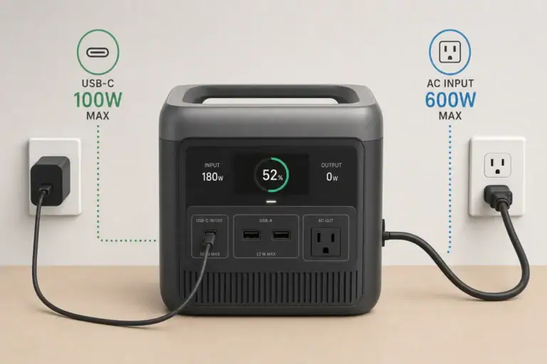
| USB-C output to USB-C input | May negotiate a supported charging rate | Shared PD profile and cable rating required |
| Battery terminals or improvised parallel wiring | Generally unsupported | Fault current and battery-management conflicts |
| Approved expansion battery connection | Designed to increase capacity | Limited to listed compatible equipment |
Real-World Daisy-Chain Examples
Charging a smaller station from a larger station
Suppose a larger station has 1,000 watt-hours of nominal capacity and powers a 200-watt AC charger for a smaller unit. The arrangement may function, but the larger station will supply more than 200 watts because its inverter has losses and its own electronics consume power. The smaller battery will also store less energy than the charger draws. This can be acceptable for occasional energy transfer, but it does not efficiently combine capacity.
Using USB-C power delivery
A USB-C port rated for 100 watts does not always supply 100 watts to another station. Both devices must support a common USB Power Delivery profile, and the cable must support the negotiated current. If the highest shared profile is 60 watts, charging will remain near that level even if one side advertises a higher maximum. Some bidirectional USB-C ports also need to determine which device is the source, so two similarly configured stations may not establish the expected direction.
Running an appliance while the upstream station charges the downstream station
If Station B runs a 600-watt appliance while receiving only 200 watts from Station A, its battery still discharges at roughly the difference, plus losses. The connection extends runtime but does not make the two inverters operate as one. The appliance remains subject to Station B’s continuous wattage and surge-watt limits.
Trying to add solar input through another station
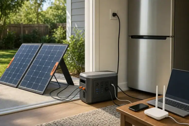
Charging one station from another does not usually increase the receiving station’s solar input limit. If its charging controller accepts a maximum of 300 watts, it cannot process 500 watts simply because the source battery was charged by solar panels. Direct solar charging within the specified voltage and current window is generally more efficient.
Common Mistakes and Troubleshooting Cues
A common mistake is assuming that matching connectors indicate matching electrical specifications. Two barrel connectors can look identical while using different voltage ranges or polarity. Do not connect them unless the documented output and input requirements are compatible.
Another mistake is comparing only watt-hours. Capacity describes stored energy, while watts describe the rate of power flow. A high-capacity station may still have a low-power port that cannot run another unit’s fast charger. Check both the port’s voltage and amperage because multiplying them gives its approximate watt limit.
If charging starts and stops repeatedly, the source may be entering overload protection, the downstream charger may have a high startup draw, or an automatic power-saving mode may be shutting off a low or fluctuating load. Repeated cycling is a cue to stop and review the specifications rather than repeatedly resetting the devices.
- No charging: Check whether the source port is enabled, whether a USB-C PD profile was negotiated, and whether the receiving input accepts the supplied voltage.
- Unexpectedly slow charging: Look for a low port limit, shared-port power reduction, an underspecified cable, thermal throttling, or a reduced charging setting.
- Source shuts down: The charger may exceed continuous output, have a brief startup surge, or trigger overload protection.
- Battery percentage falls quickly: Inverter losses, charger losses, cooling fans, and idle consumption may be larger than expected.
- Ports become unusually hot: Stop using the connection and inspect for a loose plug, damaged cable, contamination, or an underrated connector.
Also avoid confusing pass-through charging with capacity expansion. Pass-through operation routes power through or around parts of the system, depending on the design. It does not electrically merge the batteries.
Safety Basics for Connecting Power Stations
Use only documented charging inputs, supported cables, and compatible expansion accessories. Do not connect AC outlets together, attach improvised adapters to battery terminals, open an enclosure, bypass protection circuits, or attempt to parallel inverter outputs. Inverters that are not designed to synchronize can have incompatible waveforms, timing, voltage, and grounding behavior.
Keep the stations on stable, dry surfaces with ventilation around cooling openings. Conversion losses become heat, so charging one station from another can cause both units and an external power adapter to run warm. Stop using the setup if there is a burning smell, swelling, smoke, sparking, melted insulation, repeated fault warnings, or abnormal heat.
Extension cords and power strips do not increase output capacity. If one source powers multiple chargers, add their input wattage and other connected loads, then keep the total comfortably below the source’s continuous rating. A charger’s input label may be more useful for this calculation than its advertised output wattage.
Portable power stations should not be connected to home wiring through improvised cords or outlets. Any installation intended to supply household circuits requires properly rated transfer equipment and should be evaluated or installed by a qualified electrician.
Maintenance and Storage Considerations
Daisy-chaining can increase battery cycling because energy is discharged from one battery and charged into another. Frequent energy transfers may create more cumulative wear than using each station directly for separate loads. Lithium battery longevity generally benefits from moderate temperatures, avoiding unnecessary deep discharges, and limiting extended time at extreme states of charge.
Before storage, disconnect all inter-station cables and verify that ports are off. Store units in a dry location within the temperature range stated for the battery chemistry. For longer storage periods, many devices are best left at a partial charge rather than completely full or empty, but the manufacturer’s storage guidance should take priority.
Check stored stations periodically for unexpected discharge, damaged cables, debris in ports, swelling, or unusual odors. Recharge when necessary to avoid prolonged low-voltage storage. If two units have been used together, maintain them as independent devices; they may self-discharge at different rates and should not remain connected in an attempt to equalize their charge.
| Maintenance item | Example practice | Reason |
|---|---|---|
| Storage charge | Approximately 40% to 70% | Reduces time at extreme charge levels |
| Inspection interval | Every two to three months | Identifies discharge or physical damage |
| Operating clearance | Several inches around vents | Supports airflow and heat removal |
| Cable inspection | Before each energy transfer | Finds loose contacts or damaged insulation |
Related guides: Can You Use Two Portable Power Stations Together? Parallel Use Explained • Portable Power Station Expansion Batteries: When Extra Capacity Makes Sense • Input Limits (Volts/Amps/Watts) Explained: How Not to Damage Your Unit • Using a Transfer Switch With a Portable Power Station: Safe Alternatives
Practical Takeaways and Specs to Look For
Daisy-chaining portable power stations is best treated as temporary charging from one independent power source to another, not as a way to create a single larger system. AC chaining may be workable when no direct charging source is available, but repeated DC-to-AC-to-DC conversion reduces usable energy. A documented DC or USB-C connection may be more efficient when all electrical requirements match.
For more runtime, first consider whether the intended loads can be divided between two stations. Running separate appliances directly from separate stations avoids conversion losses and keeps each load within one inverter’s limits. If unified capacity is necessary, equipment designed for compatible expansion batteries is usually more predictable than connecting complete stations together.
Specs to look for
- Battery capacity: Compare usable watt-hours, such as 500 to 2,000 watt-hours, rather than relying only on nominal capacity; this helps estimate realistic runtime after conversion losses.
- Continuous AC output: Choose a rating above the combined running load, such as 1,000 watts for an 800-watt total; operating margin reduces overload shutdowns.
- Surge output: Look for a short-duration rating appropriate for motors or compressors, often 1.5 to 2 times continuous output; startup demand can exceed normal running watts.
- AC charging input: Check both maximum and adjustable charging rates, such as 200 to 1,200 watts; a lower selectable rate can prevent an upstream station from being overloaded.
- DC input range: Verify the complete voltage window, maximum amperage, polarity, and connector type; matching these values is essential for compatible DC charging.
- USB-C PD profiles: Look beyond a headline rating such as 100 or 140 watts and confirm supported voltage-current profiles; both devices need a shared profile to reach the expected rate.
- Pass-through behavior: Confirm which outputs remain active, whether output power is reduced, and whether long-duration operation is supported; implementations vary substantially.
- Expansion-battery support: Look for a documented communication port and clearly stated compatible capacity range; proper coordination allows the battery-management system to monitor the added battery.
- Cycle-life specification: Compare the stated number of cycles to a defined remaining capacity, such as 2,000 cycles to 80%; this helps assess the effect of frequent energy transfers.
- Protection and monitoring: Look for overload, overtemperature, short-circuit, overvoltage, and low-voltage protection with clear status reporting; visible input and output data makes troubleshooting easier.
If compatibility is uncertain, keep the power stations electrically independent. Using each unit for its own loads is generally safer, more efficient, and easier to troubleshoot than trying to make unrelated systems behave like one battery bank.
Frequently asked questions
Can you charge one portable power station with another?
Yes, one portable power station can sometimes charge another through a supported AC charger, DC input, or USB-C Power Delivery connection. The source output, receiving input, cable, and charging protocol must be compatible, and conversion losses mean less energy reaches the receiving battery than leaves the source.
Does daisy-chaining portable power stations combine their capacity?
No. Two complete power stations remain separate battery systems with independent inverters, battery-management systems, and shutdown limits. Charging one from the other can transfer some energy, but it does not create a single combined battery bank.
What specs matter before connecting two portable power stations?
Check the source port’s voltage, maximum current, wattage rating, connector type, and polarity against the receiving station’s documented input requirements. For USB-C, both devices need a shared Power Delivery profile and a cable rated for the negotiated power level; for AC charging, the charger input must stay below the source station’s continuous output rating.
Is it safe to connect two portable power stations with a DC cable?
It can be safe only when the manufacturer documents that the specific output and input are electrically compatible. Never rely on a connector’s physical fit alone, and do not use improvised battery-terminal wiring, polarity-changing adapters, or cables that bypass protection circuits.
Why does a portable power station shut off when charging another one?
The downstream charger may exceed the source station’s continuous output limit, create a brief startup surge, or trigger a protection feature. A power-saving mode, an undersized cable, or excessive heat can also interrupt charging, so repeated shutdowns should be investigated rather than reset repeatedly.
What is the most common mistake when daisy-chaining power stations?
A common mistake is assuming that matching plugs or similar watt-hour ratings prove compatibility. Voltage range, polarity, current limits, charging protocols, and inverter capacity must all be checked because a connector that fits may still be electrically unsafe or unable to charge properly.
Related guides
Browse this topic →
- Beginner-friendly sizing, runtime & specs
- Solar & charging (MPPT, fast charging, cables)
- Batteries (LiFePO4, cycles, care & storage)
- Safety, cold-weather performance, real-world tips
More in Charging
See all →- USB-C Input vs AC Input on Portable Power Stations: Which Charging Method Makes Sense?
- Car Alternator Charging vs Cigarette Lighter Charging: What Changes for Power Stations?
- Charging a Portable Power Station From an RV Outlet: 12V, 24V, and Safety Limits
- Fast AC Charging vs Battery Longevity: Should You Use Turbo Mode Every Time?
- Solid-State Batteries and Portable Power Stations: What Could Change?
Keep reading
About this site
Portable Energy Lab publishes practical, independent guides about portable power—clear sizing, safe use, and real-world expectations.
Affiliate disclosure
Some links on this site may be affiliate links. If you buy through these links, we may earn a small commission at no extra cost to you. This helps support our content. Read our affiliate disclosure.