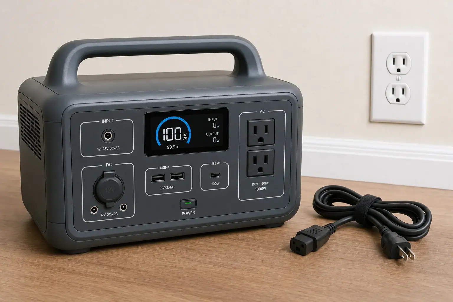
Pass-Through Solar Charging During an Outage: What Works and What to Avoid

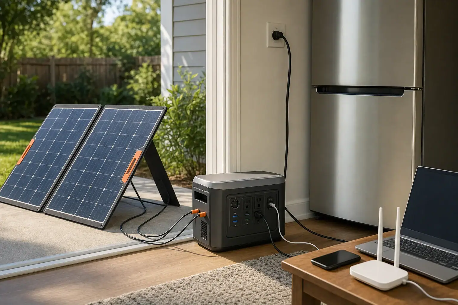
Portable power station using pass-through solar charging during an outage

Pass-through solar charging can keep a portable power station running during an outage, but it works best when solar input consistently exceeds or offsets the connected load. The station must explicitly support simultaneous charging and discharging, and its solar input limit, inverter load, battery state of charge, and temperature all affect the result.

This setup is sometimes called solar pass-through charging, simultaneous charge and discharge, or solar generator load-through operation. It should not automatically be treated as UPS mode. Even when the display shows incoming solar power, the battery may still drain if appliances consume more energy than the panels provide. Surge watts, conversion losses, changing sunlight, and the station’s own operating power also reduce runtime.

For reliable outage use, match the panels to the station’s voltage and current specifications, prioritize essential loads, and leave enough battery reserve for nighttime. Avoid unsupported connectors, overloaded outputs, unsafe indoor panel placement, and any attempt to energize household wiring without approved equipment and professional guidance.

1. What pass-through solar charging means and why it matters

Pass-through solar charging means a portable power station accepts solar energy while supplying power from its AC, DC, or USB outputs. Incoming energy may serve the connected loads, recharge the battery, or do both. The exact internal power path varies by design, so simultaneous input and output must be listed as a supported operating condition.

This feature matters during a prolonged outage because it allows daytime solar production to extend battery runtime without disconnecting essential devices. A refrigerator, communications equipment, lights, or medical support equipment may continue operating while the station harvests available sunlight. However, solar does not necessarily pass directly from the panels to the appliance. The power station commonly regulates the input, manages the battery, and converts power for the active outputs.

Pass-through operation is not the same as unlimited operation. If a 300-watt load runs while the station receives only 180 watts, the battery must provide the difference plus conversion losses. If solar input is greater than total demand, the excess can recharge the battery until charging slows near full capacity.

2. How solar input, battery power, and connected loads interact

A power station’s solar charge controller accepts a limited voltage and current range. Its maximum solar wattage is only one part of compatibility. Panel open-circuit voltage must remain below the input’s maximum voltage, including the increase that can occur in cold weather. Panel operating voltage should also fall within the controller’s usable or MPPT range. Available current may be capped even when the connected array could produce more.

Solar ratings describe favorable test conditions, not guaranteed field output. Clouds, heat, panel angle, shade, dirt, cable losses, and the time of day can reduce production. Partial shade on a small portion of a panel may cause a disproportionate drop, particularly when panel sections are electrically linked.

The basic energy balance is straightforward: solar input minus the station’s operating losses and connected loads determines whether the battery gains or loses charge. AC appliances add inverter losses, while DC and USB loads may avoid part of the conversion process. A displayed input of 400 watts and an AC load of 400 watts may therefore still produce slow battery discharge.

High starting loads require separate consideration. A refrigerator may average less than 100 watts but briefly demand several times that amount when its compressor starts. The inverter must support both continuous watts and surge watts, regardless of how much solar power is arriving at that moment.

Example values for illustration.
Operating conditionSolar inputConnected demandLikely battery behavior
Strong sun, light electronics300 W80 WBattery charges with remaining input
Variable clouds, refrigerator60–250 W70 W averageCharge level rises and falls
Cooking appliance400 W900 WBattery discharges rapidly
Battery near full500 W available120 WController may reduce solar intake

3. Real-world outage examples

Daytime refrigerator support

Consider a refrigerator averaging 70 watts over several hours, with brief compressor starts above its average draw. If the solar array delivers 250 watts in strong sun, it can cover the running demand and leave energy for charging. During clouds, input may fall below the refrigerator’s needs, causing the battery to fill the gap. The station still needs adequate inverter surge capacity for compressor startup.

Remote work and communications

A laptop, modem, router, and LED light might average 80 to 150 watts together. A suitably matched array may support these loads for much of a clear day. Using efficient USB-C or regulated DC outputs where compatible can reduce losses compared with running every device through an AC adapter. Actual savings depend on the station and device voltage requirements.

Short use of a high-power appliance

A 1,000-watt appliance used for six minutes consumes about 100 watt-hours before losses. If solar input is 300 watts during that period, the battery still supplies most of the instantaneous demand. Short operation may be practical when battery reserve is healthy, but repeated use can consume energy needed overnight.

Multi-day outage planning

During a multi-day event, daily energy is more useful than peak panel wattage. An array averaging 250 watts for four effective sun-hours yields roughly 1,000 watt-hours before cable, charging, and storage losses. Loads consuming 1,200 watt-hours per day will create an energy deficit even if the display occasionally reaches the array’s rated output.

4. Common mistakes and troubleshooting cues

Assuming simultaneous operation is supported: Some stations limit outputs during charging, reduce charging power under heavy load, or disable certain modes. Check the operating instructions for solar charging while outputs are active. Do not infer support simply because the ports can be switched on.

Comparing only panel watts: A panel array can have an acceptable watt rating but an incompatible voltage. If solar input remains at zero, review the array’s open-circuit voltage, operating voltage, polarity, connector fit, and minimum startup requirements. Never exceed the stated input voltage.

Expecting rated solar production all day: If input is lower than expected, check for shade, poor orientation, dirty surfaces, loose connections, excessive cable length, or high panel temperature. Test in direct sun with a simple load and compare results at different times of day.

Ignoring power used by the station: The inverter, display, fans, wireless features, and control electronics consume energy. A small AC load can be inefficient if the inverter must remain active continuously. Turn off output sections that are not needed.

Overloading the inverter: An overload warning, output shutdown, or repeated restart may indicate excessive continuous demand or startup surge. Disconnect nonessential loads and restart only according to the operating instructions. Do not repeatedly force the station to power an appliance beyond its ratings.

Charging stops in heat or cold: Battery management systems may reduce or stop charging outside their permitted temperature range. Move the station to a dry, ventilated environment within its specified charging range. Do not attempt to heat, cool, open, or bypass the battery system.

Using UPS expectations: Pass-through capability does not guarantee instant transfer during a utility failure. Devices that cannot tolerate a brief interruption require a power station with a documented transfer function and a transfer time suitable for the load.

5. Safety basics for outage operation

Keep the power station indoors in a dry, ventilated location unless its documentation specifically permits another environment. Solar panels generally belong outdoors, but cables should be routed to avoid water entry, pinching, trip hazards, sharp edges, and damaged insulation. Do not place the station in direct midday sun merely because the panels need sunlight.

Use connectors, adapters, and extension cables rated for the expected voltage and current. A connector that physically fits is not necessarily wired with the correct polarity. Stop using any cable or plug that becomes unusually hot, discolored, loose, or damaged.

Do not connect a portable power station to a wall receptacle to energize household circuits. Backfeeding can endanger occupants, utility workers, and equipment. Any connection to fixed home wiring requires approved transfer equipment and installation by a qualified electrician.

Preserve access to exits and smoke alarms, and keep the equipment away from flammable materials. Follow the manufacturer-defined temperature and moisture limits. If the station swells, emits an unusual odor, makes abnormal sounds, leaks, or becomes excessively hot, disconnect loads if it is safe to do so and move away from the area.

6. Maintenance and storage for reliable pass-through use

Inspect the station, panels, plugs, and cables before outage season and after heavy use. Clean solar panel surfaces using the panel maker’s recommended method, and avoid abrasive tools that can scratch the protective layer. Confirm that cooling vents are clear and that cables have not developed cracked insulation or bent contacts.

For storage, follow the stated charge-level guidance rather than leaving the battery empty for months. Many lithium-based stations are commonly stored at a partial state of charge, with periodic checks for self-discharge. Store the unit in a cool, dry place within its specified range and keep it accessible enough to test before severe weather.

Run a practical load test periodically. Confirm that the expected appliances start, the solar input is recognized, and pass-through operation remains stable. A short test can reveal a failed adapter, an unexpected appliance surge, or battery capacity loss before an outage.

Example values for illustration.
Maintenance itemExample intervalWhat to verify
Charge-level checkEvery 1–3 monthsBattery has not fallen below storage guidance
Cable inspectionBefore each deploymentNo cuts, loose plugs, corrosion, or heat damage
Solar testTwice per yearInput is detected under clear direct sun
Load testBefore outage seasonEssential devices start and run without overload

Related guides: Solar Charging in Partial Shade: Why One Shadow Can Slow the Whole SetupMC4, Anderson, DC Barrel: Solar Connectors and Adapters ExplainedPortable Power Station vs UPS: What Changes for Computers and Networking?

7. Practical takeaways and specs to look for

Pass-through solar charging works best as an energy-balancing strategy, not as a promise of endless power. Start with the daily watt-hour needs of essential devices, then consider realistic solar production and conversion losses. Keep high-draw appliances brief, preserve an overnight reserve, and monitor net battery movement rather than relying only on the solar input number.

Before buying or configuring a station for outage use, verify that simultaneous solar charging and output operation are expressly supported. Also distinguish pass-through charging from a true transfer or backup-power function. The right specifications depend on the loads, climate, available panel area, and required runtime.

Specs to look for

  • Simultaneous input and output support: Look for documented solar charging while AC, DC, and USB outputs operate; this confirms the intended outage use.
  • Solar input power: A range such as 300–1,000 watts may suit moderate systems; higher input can restore more daily energy when panel conditions allow.
  • Solar voltage range: Match panel operating voltage to the MPPT range and keep cold-weather open-circuit voltage below the maximum; this prevents incompatibility and overvoltage.
  • Input current limit: Values such as 10–20 amps determine how much array current the controller can use; excess available current may not increase charging speed.
  • Usable battery capacity: Compare watt-hours with daily load demand; about 1,000–2,000 watt-hours can support more overnight energy than a small electronics-focused unit.
  • Continuous inverter output: Choose a rating above the combined running watts of planned AC loads; operating with margin can reduce overloads and heat.
  • Surge output: Look for enough short-duration capacity to start compressors, pumps, or motors, often two or more times their running wattage.
  • Transfer function and transfer time: If uninterrupted operation matters, look for a documented backup mode and a transfer time expressed in milliseconds; pass-through support alone is insufficient.
  • Charging temperature range: A range appropriate for the intended climate helps prevent charging interruptions during very hot or cold outage conditions.
  • Input and output monitoring: Separate watt displays, remaining-time estimates, and battery percentage make it easier to identify an energy deficit before the battery is depleted.

For dependable results, test the complete setup under realistic loads before an emergency. Record typical refrigerator cycles, communication loads, solar input at different times, and overnight battery use. Those measurements provide a more reliable plan than nameplate ratings alone.

Frequently asked questions

Can a portable power station run appliances while solar panels are charging it?

It can if the power station specifically supports simultaneous solar input and output operation. Whether the battery charges or discharges depends on actual solar production, connected load, conversion losses, and the station’s own power use.

What specs matter most for pass-through solar charging?

Confirm documented simultaneous charging and output support, compatible solar voltage and current limits, usable battery capacity, and inverter continuous and surge ratings. A documented transfer function matters separately if a device needs to remain powered through a utility interruption.

Why is my power station battery draining even though the solar input display is active?

Solar input may be lower than the appliance demand after inverter and operating losses are included. Cloud cover, shade, panel angle, high panel temperature, and cable losses can also reduce the power available from the array.

Is it a mistake to choose solar panels based only on their watt rating?

Yes. The array’s open-circuit voltage, operating voltage, polarity, connector compatibility, and available current must also fit the station’s solar input specifications. An array with an acceptable watt rating can still be incompatible or unsafe if its voltage exceeds the input limit.

Can pass-through solar charging keep a refrigerator running during a power outage?

It may help extend runtime when solar production covers some or all of the refrigerator’s energy use. The power station must also have enough continuous inverter capacity and surge capacity for compressor startup, and the battery still needs reserve for low-sun periods and overnight use.

Is pass-through solar charging safe to use indoors during an outage?

The power station should be kept in a dry, ventilated indoor area only if its documentation allows it, while solar panels are generally placed outdoors. Use correctly rated cables and connectors, keep equipment away from heat and flammable materials, and never backfeed a wall outlet or fixed household wiring.

Can You Daisy-Chain Portable Power Stations? Why It Usually Isn’t a Good Idea

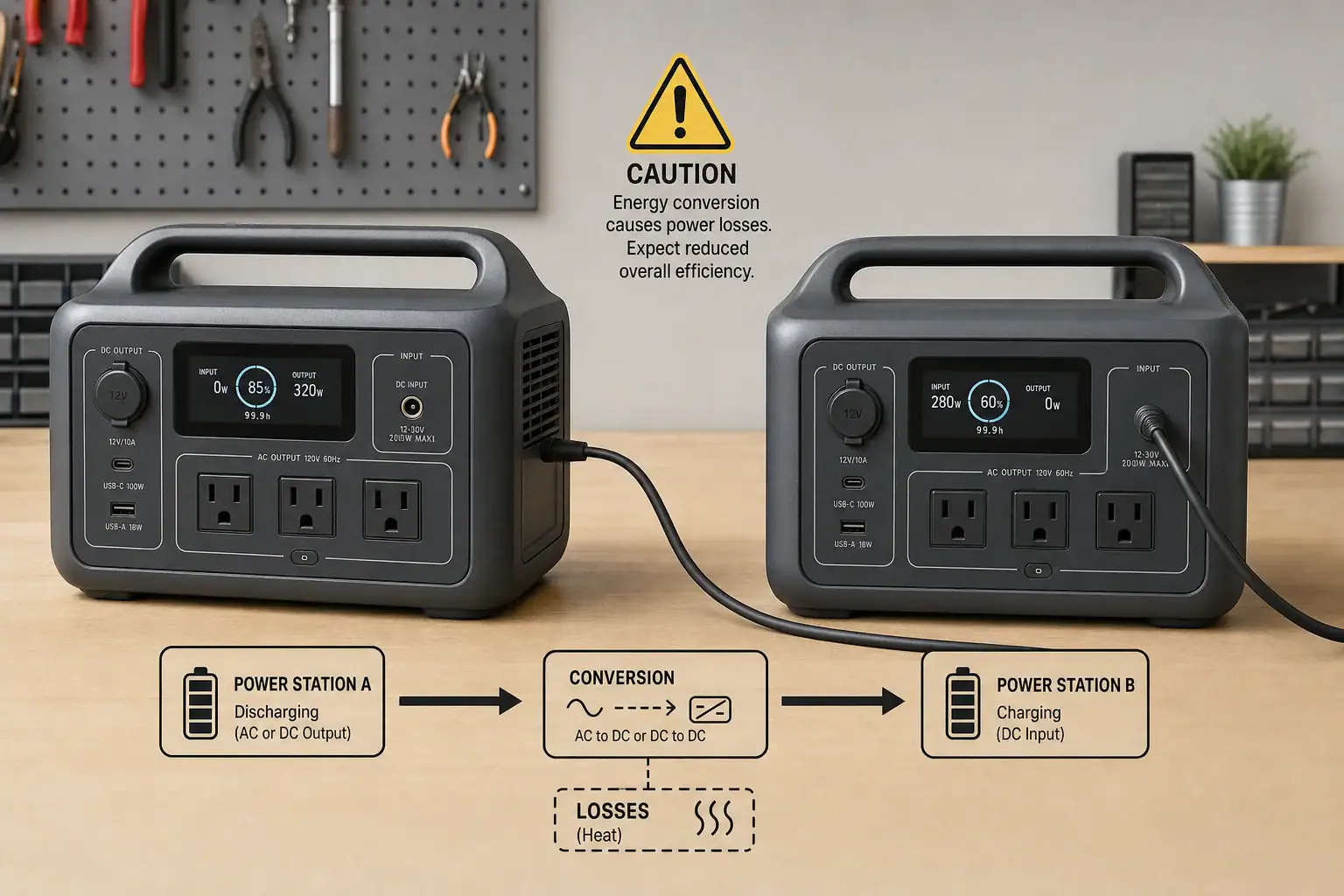
Two portable power stations connected in a daisy-chain charging arrangement

You can sometimes daisy-chain portable power stations by using one unit to charge another, but it is usually inefficient, limited, or unsupported. Portable power stations are not generally designed to have their battery outputs combined like ordinary battery cells. Differences in battery voltage, input limits, inverter ratings, charging protocols, and protection systems can prevent safe or useful operation.

The phrase “daisy-chain” may refer to several different arrangements: plugging one station’s AC charger into another station, feeding a DC output into a charging input, connecting batteries in series or parallel, or using an approved expansion battery. These methods are not equivalent. AC-to-AC chaining wastes energy through repeated conversion, while improvised DC connections can create overload, reverse-current, connector, and compatibility risks. Even when a chain works, the usable runtime is often lower than the combined watt-hour ratings suggest. For most users, a supported expansion battery, a properly sized single power station, or independent load sharing is the more predictable option.

What Daisy-Chaining Portable Power Stations Means

Daisy-chaining normally means connecting devices in sequence so power passes from one to the next. With portable power stations, the most common version is plugging the charger for Station B into the AC outlet of Station A. Station A converts battery energy from DC to AC, and Station B’s charger converts that AC back to DC. Station B may then convert the stored energy back to AC when it powers an appliance.

Some users also apply the term to a DC output-to-input connection. This may avoid one conversion stage, but it is only appropriate when the output voltage, connector, polarity, current capability, and supported charging range all match. A physical plug that fits does not prove electrical compatibility.

Connecting battery terminals or proprietary expansion ports is different. Portable power stations contain battery-management systems, fuses, contactors, and charging controls designed for a particular battery architecture. Two complete stations usually cannot coordinate those systems. Approved expansion batteries are engineered to communicate with a compatible host station; two unrelated power stations generally are not.

This distinction matters because an unsupported chain does not create one larger, synchronized battery bank. It remains two separate systems, each with its own state of charge, conversion losses, shutdown thresholds, and power limits.

How Power Flows Through a Daisy-Chain

Every conversion consumes energy. In an AC charging chain, the first station’s inverter changes battery DC into household AC. The second station’s charging adapter then changes the AC back into regulated DC. Heat, cooling fans, standby electronics, and battery charging losses reduce the energy that reaches the second battery.

For example, if the first inverter operates at 88% efficiency and the second charger operates at 90%, their combined conversion efficiency is about 79% before accounting for battery losses and idle consumption. Supplying 500 watt-hours from the first battery might therefore add substantially less than 500 watt-hours to the second.

Power limits also remain separate. A station with a 1,000-watt inverter cannot continuously supply a 1,200-watt charger merely because the downstream station has a larger battery. Likewise, a 200-watt DC port cannot deliver more than its own limit when connected to a 500-watt charging input. The receiving station will charge only at the lowest limit imposed by the source, cable, connector, charging input, or control protocol.

Pass-through charging adds another concern. Some stations can charge while powering loads, but others restrict output, reduce charging speed, or disable particular ports. Pass-through capability does not automatically mean the device is intended for continuous use as an uninterruptible power supply.

Example values for illustration.
Connection methodLikely resultMain limitation
AC outlet to AC chargerMay work as ordinary chargingMultiple conversion losses
Regulated DC output to DC inputMay work if specifications matchVoltage, current, polarity, and connector compatibility
USB-C output to USB-C inputMay negotiate a supported charging rateShared PD profile and cable rating required
Battery terminals or improvised parallel wiringGenerally unsupportedFault current and battery-management conflicts
Approved expansion battery connectionDesigned to increase capacityLimited to listed compatible equipment

Real-World Daisy-Chain Examples

Charging a smaller station from a larger station

Suppose a larger station has 1,000 watt-hours of nominal capacity and powers a 200-watt AC charger for a smaller unit. The arrangement may function, but the larger station will supply more than 200 watts because its inverter has losses and its own electronics consume power. The smaller battery will also store less energy than the charger draws. This can be acceptable for occasional energy transfer, but it does not efficiently combine capacity.

Using USB-C power delivery

A USB-C port rated for 100 watts does not always supply 100 watts to another station. Both devices must support a common USB Power Delivery profile, and the cable must support the negotiated current. If the highest shared profile is 60 watts, charging will remain near that level even if one side advertises a higher maximum. Some bidirectional USB-C ports also need to determine which device is the source, so two similarly configured stations may not establish the expected direction.

Running an appliance while the upstream station charges the downstream station

If Station B runs a 600-watt appliance while receiving only 200 watts from Station A, its battery still discharges at roughly the difference, plus losses. The connection extends runtime but does not make the two inverters operate as one. The appliance remains subject to Station B’s continuous wattage and surge-watt limits.

Trying to add solar input through another station

Charging one station from another does not usually increase the receiving station’s solar input limit. If its charging controller accepts a maximum of 300 watts, it cannot process 500 watts simply because the source battery was charged by solar panels. Direct solar charging within the specified voltage and current window is generally more efficient.

Common Mistakes and Troubleshooting Cues

A common mistake is assuming that matching connectors indicate matching electrical specifications. Two barrel connectors can look identical while using different voltage ranges or polarity. Do not connect them unless the documented output and input requirements are compatible.

Another mistake is comparing only watt-hours. Capacity describes stored energy, while watts describe the rate of power flow. A high-capacity station may still have a low-power port that cannot run another unit’s fast charger. Check both the port’s voltage and amperage because multiplying them gives its approximate watt limit.

If charging starts and stops repeatedly, the source may be entering overload protection, the downstream charger may have a high startup draw, or an automatic power-saving mode may be shutting off a low or fluctuating load. Repeated cycling is a cue to stop and review the specifications rather than repeatedly resetting the devices.

  • No charging: Check whether the source port is enabled, whether a USB-C PD profile was negotiated, and whether the receiving input accepts the supplied voltage.
  • Unexpectedly slow charging: Look for a low port limit, shared-port power reduction, an underspecified cable, thermal throttling, or a reduced charging setting.
  • Source shuts down: The charger may exceed continuous output, have a brief startup surge, or trigger overload protection.
  • Battery percentage falls quickly: Inverter losses, charger losses, cooling fans, and idle consumption may be larger than expected.
  • Ports become unusually hot: Stop using the connection and inspect for a loose plug, damaged cable, contamination, or an underrated connector.

Also avoid confusing pass-through charging with capacity expansion. Pass-through operation routes power through or around parts of the system, depending on the design. It does not electrically merge the batteries.

Safety Basics for Connecting Power Stations

Use only documented charging inputs, supported cables, and compatible expansion accessories. Do not connect AC outlets together, attach improvised adapters to battery terminals, open an enclosure, bypass protection circuits, or attempt to parallel inverter outputs. Inverters that are not designed to synchronize can have incompatible waveforms, timing, voltage, and grounding behavior.

Keep the stations on stable, dry surfaces with ventilation around cooling openings. Conversion losses become heat, so charging one station from another can cause both units and an external power adapter to run warm. Stop using the setup if there is a burning smell, swelling, smoke, sparking, melted insulation, repeated fault warnings, or abnormal heat.

Extension cords and power strips do not increase output capacity. If one source powers multiple chargers, add their input wattage and other connected loads, then keep the total comfortably below the source’s continuous rating. A charger’s input label may be more useful for this calculation than its advertised output wattage.

Portable power stations should not be connected to home wiring through improvised cords or outlets. Any installation intended to supply household circuits requires properly rated transfer equipment and should be evaluated or installed by a qualified electrician.

Maintenance and Storage Considerations

Daisy-chaining can increase battery cycling because energy is discharged from one battery and charged into another. Frequent energy transfers may create more cumulative wear than using each station directly for separate loads. Lithium battery longevity generally benefits from moderate temperatures, avoiding unnecessary deep discharges, and limiting extended time at extreme states of charge.

Before storage, disconnect all inter-station cables and verify that ports are off. Store units in a dry location within the temperature range stated for the battery chemistry. For longer storage periods, many devices are best left at a partial charge rather than completely full or empty, but the manufacturer’s storage guidance should take priority.

Check stored stations periodically for unexpected discharge, damaged cables, debris in ports, swelling, or unusual odors. Recharge when necessary to avoid prolonged low-voltage storage. If two units have been used together, maintain them as independent devices; they may self-discharge at different rates and should not remain connected in an attempt to equalize their charge.

Example values for illustration.
Maintenance itemExample practiceReason
Storage chargeApproximately 40% to 70%Reduces time at extreme charge levels
Inspection intervalEvery two to three monthsIdentifies discharge or physical damage
Operating clearanceSeveral inches around ventsSupports airflow and heat removal
Cable inspectionBefore each energy transferFinds loose contacts or damaged insulation

Related guides: Can You Use Two Portable Power Stations Together? Parallel Use ExplainedPortable Power Station Expansion Batteries: When Extra Capacity Makes SenseInput Limits (Volts/Amps/Watts) Explained: How Not to Damage Your UnitUsing a Transfer Switch With a Portable Power Station: Safe Alternatives

Practical Takeaways and Specs to Look For

Daisy-chaining portable power stations is best treated as temporary charging from one independent power source to another, not as a way to create a single larger system. AC chaining may be workable when no direct charging source is available, but repeated DC-to-AC-to-DC conversion reduces usable energy. A documented DC or USB-C connection may be more efficient when all electrical requirements match.

For more runtime, first consider whether the intended loads can be divided between two stations. Running separate appliances directly from separate stations avoids conversion losses and keeps each load within one inverter’s limits. If unified capacity is necessary, equipment designed for compatible expansion batteries is usually more predictable than connecting complete stations together.

Specs to look for

  • Battery capacity: Compare usable watt-hours, such as 500 to 2,000 watt-hours, rather than relying only on nominal capacity; this helps estimate realistic runtime after conversion losses.
  • Continuous AC output: Choose a rating above the combined running load, such as 1,000 watts for an 800-watt total; operating margin reduces overload shutdowns.
  • Surge output: Look for a short-duration rating appropriate for motors or compressors, often 1.5 to 2 times continuous output; startup demand can exceed normal running watts.
  • AC charging input: Check both maximum and adjustable charging rates, such as 200 to 1,200 watts; a lower selectable rate can prevent an upstream station from being overloaded.
  • DC input range: Verify the complete voltage window, maximum amperage, polarity, and connector type; matching these values is essential for compatible DC charging.
  • USB-C PD profiles: Look beyond a headline rating such as 100 or 140 watts and confirm supported voltage-current profiles; both devices need a shared profile to reach the expected rate.
  • Pass-through behavior: Confirm which outputs remain active, whether output power is reduced, and whether long-duration operation is supported; implementations vary substantially.
  • Expansion-battery support: Look for a documented communication port and clearly stated compatible capacity range; proper coordination allows the battery-management system to monitor the added battery.
  • Cycle-life specification: Compare the stated number of cycles to a defined remaining capacity, such as 2,000 cycles to 80%; this helps assess the effect of frequent energy transfers.
  • Protection and monitoring: Look for overload, overtemperature, short-circuit, overvoltage, and low-voltage protection with clear status reporting; visible input and output data makes troubleshooting easier.

If compatibility is uncertain, keep the power stations electrically independent. Using each unit for its own loads is generally safer, more efficient, and easier to troubleshoot than trying to make unrelated systems behave like one battery bank.

Frequently asked questions

Can you charge one portable power station with another?

Yes, one portable power station can sometimes charge another through a supported AC charger, DC input, or USB-C Power Delivery connection. The source output, receiving input, cable, and charging protocol must be compatible, and conversion losses mean less energy reaches the receiving battery than leaves the source.

Does daisy-chaining portable power stations combine their capacity?

No. Two complete power stations remain separate battery systems with independent inverters, battery-management systems, and shutdown limits. Charging one from the other can transfer some energy, but it does not create a single combined battery bank.

What specs matter before connecting two portable power stations?

Check the source port’s voltage, maximum current, wattage rating, connector type, and polarity against the receiving station’s documented input requirements. For USB-C, both devices need a shared Power Delivery profile and a cable rated for the negotiated power level; for AC charging, the charger input must stay below the source station’s continuous output rating.

Is it safe to connect two portable power stations with a DC cable?

It can be safe only when the manufacturer documents that the specific output and input are electrically compatible. Never rely on a connector’s physical fit alone, and do not use improvised battery-terminal wiring, polarity-changing adapters, or cables that bypass protection circuits.

Why does a portable power station shut off when charging another one?

The downstream charger may exceed the source station’s continuous output limit, create a brief startup surge, or trigger a protection feature. A power-saving mode, an undersized cable, or excessive heat can also interrupt charging, so repeated shutdowns should be investigated rather than reset repeatedly.

What is the most common mistake when daisy-chaining power stations?

A common mistake is assuming that matching plugs or similar watt-hour ratings prove compatibility. Voltage range, polarity, current limits, charging protocols, and inverter capacity must all be checked because a connector that fits may still be electrically unsafe or unable to charge properly.

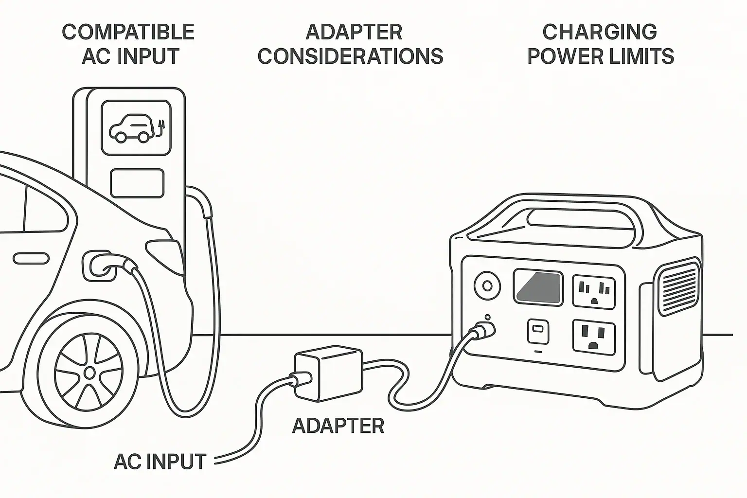
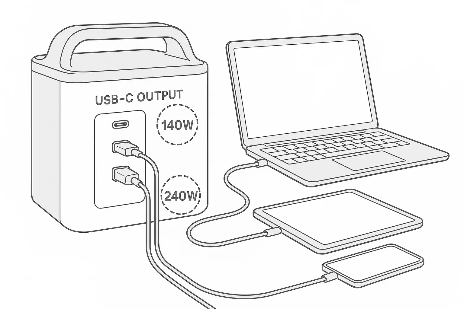
USB-C Input vs AC Input on Portable Power Stations: Which Charging Method Makes Sense?

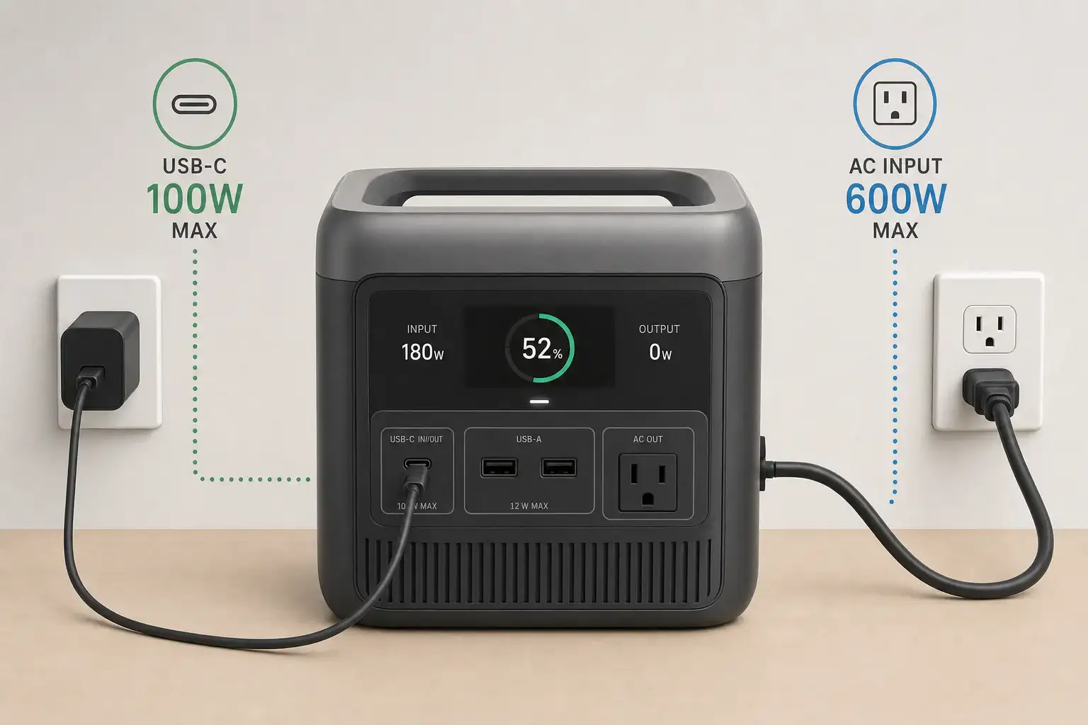
USB-C input compared with AC input on a portable power station

AC input usually makes the most sense when charging speed matters, while USB-C input is better for portability, convenience, and using one charger across several devices. The right choice depends on the power station’s input limit, supported USB Power Delivery profile, battery capacity, and the output rating of the charger.

For a large power station, AC charging may provide several hundred or even more than 1,000 watts, substantially reducing recharge time. USB-C charging commonly operates at lower wattage, although higher-power USB-C PD systems can be practical for compact and midsize models. Advertised charger wattage alone does not determine the result because the station, cable, and charger must agree on a compatible charging profile.

Efficiency, charging time, cable requirements, and whether a USB-C port is input-only or bidirectional also matter. Comparing these details helps determine whether USB-C can serve as the primary charging method or should remain a travel-friendly backup.

1. What USB-C Input and AC Input Mean

USB-C input allows a portable power station to receive direct current through a USB-C connector, usually under the USB Power Delivery, or USB PD, standard. The charger and power station negotiate a supported voltage and current. Charging begins at a mutually supported level rather than automatically using the largest number printed on either device.

AC input accepts power associated with a household wall outlet. Depending on the design, the station may contain an internal AC-to-DC charging circuit or use an external power adapter. In either case, AC from the outlet must be converted into the controlled DC voltage needed by the battery.

The distinction matters because it affects recharge speed, equipment requirements, and packing convenience. AC input generally supports more charging power and is often preferred before an outage or trip. USB-C may eliminate a dedicated adapter and can work with a compact charger already used for a laptop or other electronics. However, a USB-C connector does not guarantee high-wattage charging.

2. How Charging Power, PD Profiles, and Input Limits Work

Charging power is measured in watts and is broadly calculated by multiplying voltage by current. A 20-volt, 5-amp USB-C profile represents 100 watts, while newer extended-power profiles can support higher values when every component is compatible. Actual battery charging power may be lower because energy is consumed by conversion losses, thermal management, and any loads running from the station.

The lowest relevant limit controls USB-C performance. A 140-watt charger will not deliver 140 watts if the power station accepts only 100 watts, the cable is rated for less, or the required PD profile is unavailable. Some high-current cables contain an electronic marker that identifies their capabilities. An ordinary charging cable may therefore reduce power or prevent a high-power profile from being selected.

AC charging is also limited by the station’s rated AC input, not merely by the wall circuit. Many stations intentionally slow charging near a high state of charge or when battery temperature is outside the preferred range. This charging curve protects the battery, so dividing capacity in watt-hours by maximum input watts provides only a rough minimum time rather than a guaranteed result.

Comparison pointUSB-C inputAC input
Typical rolePortable or secondary chargingFast primary charging
Illustrative input power45–240 watts300–1,800 watts
EquipmentCompatible PD charger and cableAC cord or supplied adapter
Main limitationShared PD profile and cable ratingStation’s AC input rating and heat
Travel convenienceOften compact and multipurposeMay require dedicated hardware
General comparison of charging inputs. Example values for illustration.

3. Real-World Charging Examples

Compact 300-watt-hour power station

Suppose a compact station has a 300-watt-hour battery, accepts 100-watt USB-C PD input, and supports 200-watt AC input. USB-C might require roughly four hours after normal losses and end-of-charge tapering. AC could reduce that to around two hours. USB-C remains attractive if the owner already carries a compatible laptop charger and does not need an immediate turnaround.

Midsize 1,000-watt-hour power station

A 1,000-watt-hour model with 100-watt USB-C input would need well over ten hours for a full charge under typical conditions. If its AC input accepts 800 watts, AC charging could complete the job in a few hours. In this case, USB-C is useful for overnight charging, topping up, or situations where only a lower-power source is available, but it is less practical before a time-sensitive outage.

Charging while powering equipment

If a station receives 100 watts through USB-C while supplying an average 70-watt load, only part of the incoming power is available to increase the battery’s state of charge. Conversion and operating overhead can narrow that margin further. The battery percentage may rise slowly, stay level, or fall. AC input with a higher wattage ceiling provides more headroom, although simultaneous charging and discharging should still remain within the manufacturer’s operating guidance.

4. Common Mistakes and Troubleshooting Cues

Assuming every USB-C port accepts input: Some ports are output-only, while others support bidirectional power. Check the port label and input specification. A display that shows no incoming watts may indicate the wrong port rather than a failed charger.

Matching wattage but not the PD profile: Two products can advertise the same maximum wattage yet lack a shared voltage profile. In that situation, they may negotiate a slower level. Compare supported input voltages and currents, not just headline watts.

Using an unsuitable cable: A cable designed mainly for data or lower-current phone charging can bottleneck the system. If charging repeatedly starts and stops, test with an intact cable explicitly rated for the intended USB-C power level.

Expecting a constant maximum rate: Charging commonly slows as the battery approaches full charge or becomes hot or cold. A lower reading near 90 percent may be normal. Persistent low input at a moderate state of charge may point to charger sharing, a cable limitation, temperature protection, or an enabled quiet-charging mode.

Overlooking shared charger output: Multiport USB-C chargers often divide their total output when more than one device is connected. Disconnecting another device may allow the power station to negotiate a higher profile.

Comparing charging time with nominal capacity alone: A 1,000-watt-hour rating describes stored energy under defined conditions, not wall energy consumed during charging. Conversion losses and battery balancing add time. If AC charging shows zero input, verify that the cord is fully seated, the outlet works, and any input setting is enabled. Stop using equipment that has damaged connectors, unusual heat, odor, or repeated fault warnings.

5. Charging Safety Basics

Use chargers, cords, and USB-C cables whose voltage, current, and power ratings are compatible with the station. Do not use damaged, loose, scorched, or unusually hot connectors. Place the power station on a stable, dry surface with ventilation openings unobstructed, and keep it away from flammable materials and direct heat.

High-power AC charging can create more heat and may place a meaningful load on a household circuit. Avoid overloading extension cords or power strips, and do not use lightweight cords that are not rated for the load. If an outlet is loose, discolored, buzzing, or repeatedly trips protection, stop using it and consult a qualified electrician.

Do not open the power station, modify its battery pack, bypass protection systems, or improvise connections to household electrical panels. Charging outdoors requires equipment and receptacles appropriate for the environment, with protection from rain and standing water. Follow the operating temperature range and pause charging if the unit reports a temperature or battery fault.

6. Maintenance and Storage for Reliable Input Performance

Keep USB-C sockets, AC inlets, and cable ends clean and dry. Dust can be removed from the surrounding surface with the unit disconnected, but metal objects and liquids should never be inserted into a port. Replace cables that have bent plugs, cracked insulation, fraying, or an unreliable connection.

For storage, follow the specified state-of-charge range and recharge interval. Many lithium battery systems are better stored partially charged than left at zero or 100 percent for long periods. Extreme heat accelerates battery aging, while very cold conditions can temporarily restrict charging.

Periodically test both inputs before emergency use. A short charging check can reveal a missing adapter, damaged cable, firmware-related setting, or charger compatibility issue. After storage, allow a unit that has been in a very hot or cold location to reach an acceptable temperature before charging.

Battery capacityUSB-C input exampleAC input exampleLikely use case
300 Wh100 W200 WEither method can be practical
600 Wh140 W500 WUSB-C overnight; AC for speed
1,000 Wh100 W800 WAC primary; USB-C backup
2,000 Wh240 W1,500 WAC usually better for full recharges
Illustrative capacity and input combinations, not guaranteed charging times. Example values for illustration.

Related guides: USB-C Power Delivery (PD) Explained for Portable Power StationsInput Limits (Volts/Amps/Watts) Explained: How Not to Damage Your UnitHow Long Does It Take to Charge a Portable Power Station?Dual Input Explained: Can You Combine Wall + Solar Charging Safely?

7. Which Charging Method Makes Sense and What Specs Matter?

Choose AC input when rapid recovery, a large battery, or frequent deep discharges make charging time important. Choose USB-C when compact equipment, travel convenience, and charger sharing matter more than speed. For a small station, a strong USB-C input may be sufficient as the main method. For a large station, USB-C is usually more useful as a supplementary or backup input.

The most flexible design supports both methods without relying on vague port labels. Estimate recharge time from usable capacity and realistic input power, then allow extra time for losses and charging taper. Also consider whether the station can combine solar or other inputs, since some models share internal input limits even when several connectors are present.

Specs to look for

  • Maximum USB-C input: Look for roughly 100–240 watts when faster USB-C charging is important; a higher ceiling can shorten charging time on compatible stations.
  • Supported PD profiles: Look for listed voltage and current combinations, such as 20 volts at 5 amps; matching profiles prevent an unexpected fallback to slower charging.
  • USB-C port direction: Confirm whether the port is input-only, output-only, or bidirectional; this determines whether it can charge the battery.
  • Maximum AC input: Compare values such as 300, 800, or 1,500 watts with battery capacity; higher input is especially valuable for large batteries.
  • Estimated full recharge time: Look for test conditions and the stated charging mode; this is more useful than maximum watts alone because charging power tapers.
  • Adjustable charging rate: A selectable low, standard, or fast mode can reduce noise and circuit demand when maximum speed is unnecessary.
  • Cable requirements: Check whether high-power USB-C operation needs a 5-amp electronically marked cable; the wrong cable can limit input.
  • Input behavior under load: Look for information about simultaneous charging and output; adequate input headroom helps prevent the battery from draining during use.
  • Operating temperature range: A clearly stated charging range helps predict when thermal protection may slow or stop input.

AC input is the practical default for the fastest recharge, but USB-C can be the better everyday option for compact stations and lighter travel setups. The deciding factors are battery size, accepted input watts, compatible PD profiles, cable capability, and how quickly the stored energy must be restored.

Frequently asked questions

Is USB-C charging fast enough for a portable power station?

USB-C charging can be fast enough for compact power stations, particularly when the station accepts 100 watts or more and charging can occur overnight. For larger batteries, its lower input wattage usually makes AC the more practical option when a full recharge is needed quickly.

Can I use any USB-C laptop charger to charge a power station?

Not always. The charger, cable, and power station must support a compatible USB Power Delivery voltage and current profile, and the station’s USB-C port must be designed to accept input. A charger may still work at a lower power level if the highest profile is not shared.

Why is my power station charging slowly through USB-C?

A common mistake is using a cable that is not rated for the required power or assuming that a high-wattage charger guarantees high-wattage input. Charging can also slow because another device is sharing a multiport charger, the battery is warm or cold, or the station is nearing full capacity.

What specs should I compare before choosing USB-C input or AC input?

Compare the station’s maximum USB-C and AC input ratings, supported USB PD voltage and current profiles, battery capacity, and stated recharge time. Also check whether the USB-C port supports input, whether a higher-power cable is required, and whether charging speed changes while the station is powering other equipment.

Can a power station charge and run devices at the same time?

Many models can charge while supplying power, but the battery only gains energy when incoming power exceeds the station’s output load and operating overhead. Review the manufacturer’s limits for simultaneous input and output, because some units reduce charging speed or restrict certain modes.

Is it safe to charge a power station with USB-C or AC power?

Both methods can be safe when compatible, undamaged chargers and cables are used according to the power station’s instructions. Charge on a dry, stable, ventilated surface, avoid damaged or overheating connectors, and stop charging if the unit reports a fault or shows unusual heat, odor, or discoloration.

Car Alternator Charging vs Cigarette Lighter Charging: What Changes for Power Stations?

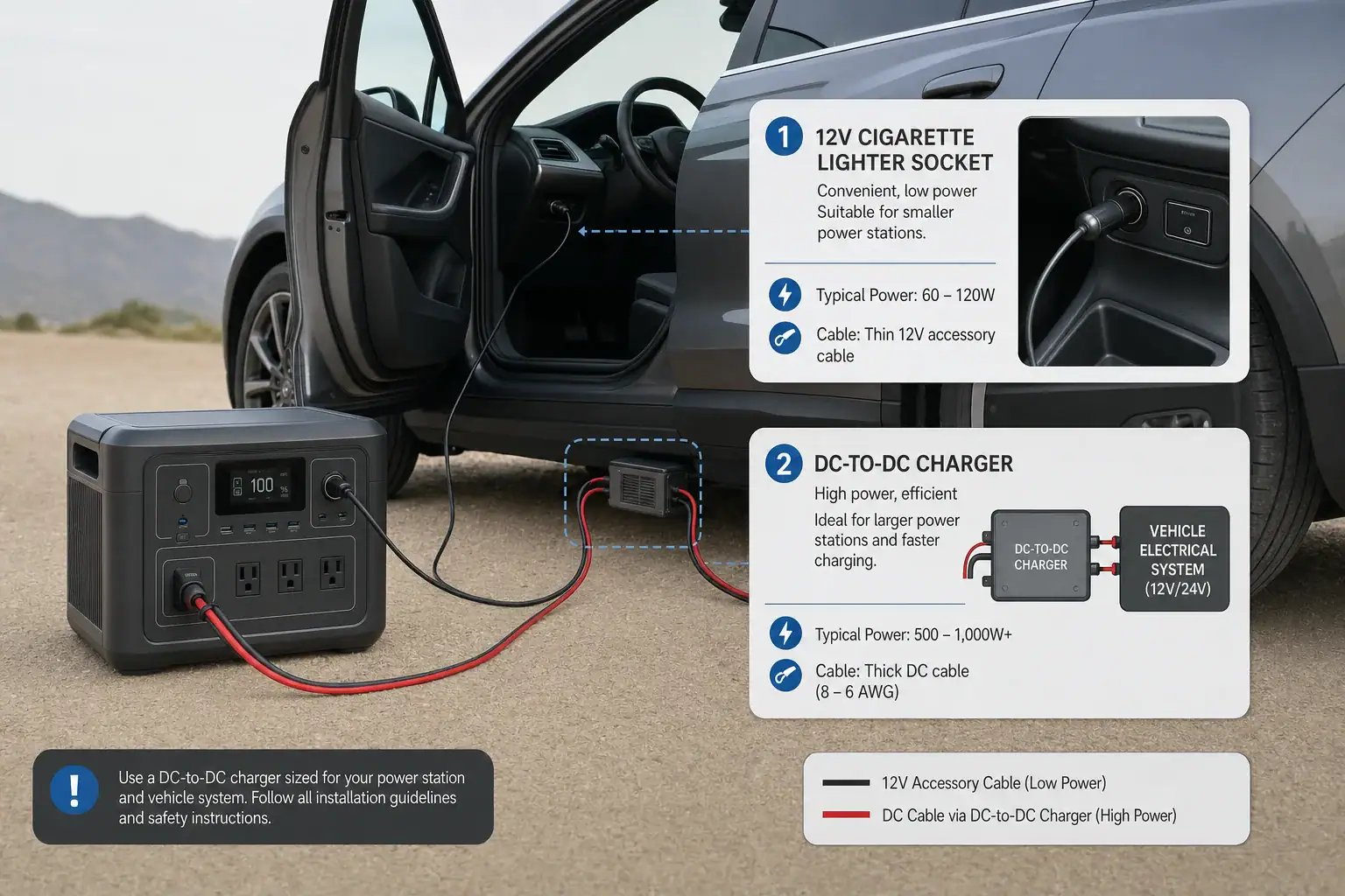
Comparison of car alternator and cigarette lighter charging for a portable power station

Car alternator charging can deliver substantially more power to a portable power station than cigarette lighter charging, but only when a compatible, regulated vehicle charging system is used. A dashboard 12-volt socket is limited by its fuse, wiring, connector, and the power station’s DC input limit. A dedicated alternator charger can use heavier cabling and controlled DC-to-DC conversion to support a higher charging rate.

In practical terms, cigarette lighter charging commonly supplies about 60 to 120 watts after conversion losses, while a properly designed alternator charging setup may provide several hundred watts. Actual performance depends on charging watts, input voltage range, current limit, cable gauge, alternator capacity, and engine speed.

The faster option is not automatically suitable for every vehicle or power station. The charging source must match the station’s supported input, and the vehicle must have enough electrical capacity for both charging and normal operation. Modern smart alternators, starter-battery protection, heat, and connector quality can also change the result.

1. What Alternator Charging and Cigarette Lighter Charging Mean

Cigarette lighter charging uses the vehicle’s factory-installed 12-volt accessory socket. A compatible cable connects that socket to a power station’s vehicle or DC input. Although the socket is ultimately supplied by the vehicle electrical system, the factory circuit is intentionally limited. Many accessory circuits have 10-amp or 15-amp fuses, and other loads may share the same circuit.

Alternator charging usually refers to a dedicated high-current charging path connected to the vehicle electrical system through an appropriate fuse, heavier cable, and a regulated DC-to-DC charger. That charger provides voltage and current the power station can accept. It may also offer ignition sensing or low-voltage protection so charging stops when the engine is off.

This distinction matters because a power station does not draw unlimited energy simply because the alternator has a high output rating. The lowest limit in the charging chain determines performance. That limit may be the socket fuse, cable, converter, connector, power station input, alternator output at idle, or the remaining capacity after the vehicle’s own electrical loads are supplied.

Directly attaching an ordinary power station input to an alternator or starter battery is not a substitute for a compatible charger. Vehicle voltage varies, electrical systems can produce transients, and a station’s solar or DC port may require a specific voltage range, polarity, connector, and current ceiling.

2. How the Two Charging Methods Work

With cigarette lighter charging, the alternator supports the vehicle’s electrical bus while the engine is running. Power passes through the starter battery and charging system, the accessory-circuit fuse, relatively small factory wiring, the socket, and the charging cable. The power station then regulates that input for its internal battery.

A nominal 12-volt, 10-amp socket might appear to offer 120 watts. In reality, voltage drop, conservative device limits, cable resistance, and conversion losses can reduce battery charging power. The plug may also become warm because its spring contacts have limited surface area.

A dedicated alternator charger takes a higher controlled current through wiring sized for the load. A DC-to-DC stage can stabilize or boost voltage to a level supported by the power station. For example, a charger could convert vehicle-side power into a regulated 24-volt or 48-volt output. Higher voltage allows the same wattage to travel at lower output current, although the vehicle-side input still carries substantial current.

Charging time depends on more than the advertised wattage. A rough estimate divides the energy needed in watt-hours by the effective charging watts, then allows extra time for conversion losses and charge-rate tapering near full capacity. Battery temperature, state of charge, simultaneous AC or USB loads, and the station’s battery management system can all reduce the observed rate.

CharacteristicCigarette lighter chargingDedicated alternator charging
Typical charging rangeAbout 60–120 wattsAbout 200–800 watts, system dependent
Vehicle connectionFactory accessory socketFused, heavier dedicated wiring
Voltage regulationUsually handled by the station or cableUsually handled by a DC-to-DC charger
InstallationPlug-and-use when compatibleVehicle-specific installation may be required
Main limitationSocket, fuse, wiring, and input currentCharger rating, station input, and vehicle capacity
Best general useSlow charging during routine drivingFaster replenishment during longer drives
Example values for illustration.

3. Real-World Charging Examples

Small power station through a 12-volt socket

Consider a 500-watt-hour power station receiving 90 watts from an accessory socket. If it needs 400 watt-hours to reach the desired charge level, simple division suggests about 4.4 hours. Allowing for losses and charging taper, the trip may need to last roughly five hours. Running a 40-watt device from the station at the same time could reduce net battery charging to around 50 watts and significantly extend the time.

Medium power station with dedicated alternator charging

A 1,000-watt-hour station might accept 500 watts from a compatible regulated vehicle charger. Adding 800 watt-hours could take around two hours after accounting for normal losses and tapering. However, this result requires the station to accept that input power and the vehicle to sustain the charger’s demand without excessive voltage drop or alternator heating.

High-power charger limited by the station

A vehicle charger rated for 800 watts will not deliver 800 watts if the power station’s relevant input is capped at 400 watts. Some stations also have separate limits for vehicle, solar, and combined charging. Connector voltage may further constrain power. A 12-volt input limited to 10 amps cannot accept the same power as a regulated higher-voltage input rated for several hundred watts.

Alternator output that changes at idle

An alternator advertised with a high maximum rating may produce less current at idle. Headlights, climate-control blowers, window defrosters, engine electronics, and cooling fans receive priority. A charger may reduce output or disconnect if vehicle voltage falls. Smart alternators can also lower bus voltage when the starter battery is sufficiently charged, causing an unregulated charging source to slow or cycle.

4. Common Mistakes and Troubleshooting Cues

  • Assuming the socket’s fuse rating equals charging power: A 15-amp fuse does not mean a station should continuously draw 15 amps. The device, cable, plug, wiring, and shared loads may impose lower limits.
  • Using the wrong input mode: Some power stations distinguish between vehicle input and solar input. An incorrect setting or incompatible voltage can cause low charging power or prevent charging.
  • Ignoring connector fit: A loose accessory plug increases resistance. Intermittent charging, a hot plug, discoloration, or charging that stops over bumps points to a poor connection.
  • Expecting maximum watts at every state of charge: Charging power often drops near full capacity or when the battery is too hot or cold. A lower rate near 90% may be normal.
  • Counting gross rather than net charging: Appliances connected to the power station consume part of the incoming energy. The display may show input power while the battery percentage rises slowly.
  • Charging with the engine off: An always-on socket or improperly controlled dedicated charger can discharge the starter battery. If charging stops with the ignition, that behavior may be intentional.
  • Overlooking cable voltage drop: Long, thin cables can cause low input voltage, reduced wattage, cycling, or shutdown. Dedicated high-current systems require cable sizing based on current, length, routing, and allowable voltage drop.

For troubleshooting, first compare the displayed input watts with the rated limit for the exact port being used. Then check whether the engine is running, other vehicle loads are active, the plug is fully seated, and the station is within a normal temperature range. Repeated fuse failures, burning odors, melted plastic, or unusually hot wiring require immediate disconnection and professional inspection rather than a larger fuse.

5. Safety Basics for Vehicle Charging

Use only charging equipment whose voltage range, polarity, connector, and current are compatible with the power station. A dedicated alternator charger should include suitable input and output protection, regulation, and a method of preventing starter-battery depletion. Installation quality matters because high current can create substantial heat at a loose terminal or undersized cable.

Fuses protect wiring and should be selected for the cable and equipment, not enlarged to stop nuisance blowing. A blown factory accessory fuse can indicate excessive current, a damaged plug, a short circuit, or another load on the same circuit. Replacing it with a higher rating can leave the original wiring unprotected.

Keep charging cables away from exhaust components, sharp edges, pedals, seat tracks, and moving engine parts. Maintain airflow around the power station and charger. Do not charge a station that is swollen, physically damaged, wet, leaking, or producing an unusual odor.

Alternator and DC-to-DC charger installations vary by vehicle, especially in vehicles with battery monitoring sensors, start-stop systems, smart alternators, multiple batteries, or high-voltage hybrid components. A qualified automotive electrician should assess any permanent high-current installation. Hybrid and electric vehicles may have a conventional low-voltage accessory system, but their traction batteries and high-voltage wiring are not user connection points.

6. Maintenance and Storage Considerations

Inspect accessory plugs and charging cables periodically for looseness, bent contacts, abrasion, corrosion, or heat damage. Dust and oxidation can increase resistance. Connectors should remain dry and should not require force to stay seated. A plug that becomes progressively hotter during similar trips may be deteriorating even if charging still works.

For a permanent alternator charging system, periodic checks should include visible cable routing, strain relief, fuse-holder condition, and secure mounting. Any terminal inspection requiring access to vehicle electrical connections should follow the vehicle and charger documentation or be handled by a professional. Do not open the power station, charger, or battery pack.

Before storing the vehicle, disconnect portable charging equipment if it has standby consumption or lacks reliable ignition control. Long-term parasitic draw can weaken the starter battery. Store the power station at the charge level and temperature recommended for its battery chemistry, and recharge it periodically if the manufacturer specifies a storage interval.

Extreme cabin temperatures can shorten battery life and may prevent charging. Avoid leaving a power station in a parked vehicle during very hot or freezing conditions. If the station has been exposed to temperature extremes, allow it to return to its permitted charging range before use.

Observed symptomPossible causeAppropriate response
Input falls when headlights or blower startLimited alternator reserve or voltage dropReduce charging demand and have system capacity checked
Accessory plug is hotLoose contact, high resistance, or excessive currentStop charging and inspect the plug and socket
Charging cycles on and offLow voltage, smart alternator behavior, or thermal protectionCheck displayed voltage, temperature, and charger compatibility
Battery percentage rises slowlyConnected loads or normal conversion lossesCompare input power with simultaneous output power
Starter battery is weak after parkingCharging continued with the engine offUse ignition control or low-voltage cutoff
Example values for illustration.

Related guides: Car Charging Explained: 12V Socket vs DC-DC Charger vs Alternator (Speed + Safety)Charging From a Car: What’s Safe, What’s Slow, and What Can BreakCan You Use a Higher-Watt Charger Than Rated? Understanding Input Headroom

7. Practical Takeaways and Specs to Look For

Cigarette lighter charging is the simpler option for modest energy needs and long drives. It requires no permanent installation when the socket, cable, and power station are compatible, but its charging speed is usually limited to roughly 60 to 120 watts. It works best for smaller stations, maintenance charging, or replacing energy used by light loads.

Dedicated alternator charging is more appropriate when a larger station must recover several hundred watt-hours during a drive. Its advantages come from regulated conversion, heavier wiring, and higher supported current—not from connecting the station directly to the alternator. The vehicle’s electrical reserve and the station’s input specification must support the intended charging rate.

Specs to look for

  • Vehicle-input power: Look for a clearly stated rating such as 100, 400, or 800 watts; this indicates the maximum useful charging speed from the relevant vehicle setup.
  • DC input voltage range: Check for a range that matches the charger output, such as approximately 12–30 volts or 16–60 volts; an incompatible range can prevent charging.
  • Input current limit: Compare limits such as 8, 10, 15, or 20 amps with the cable and source; current caps often explain why actual watts are below expectations.
  • Regulated DC-to-DC output: Look for stable voltage and current matched to the station; regulation helps manage smart alternator behavior and vehicle-voltage variation.
  • Starter-battery protection: Ignition sensing or an adjustable low-voltage cutoff can stop charging when the engine is off or vehicle voltage falls.
  • Adjustable charging rate: Settings such as 200, 400, and 600 watts allow demand to be reduced for smaller alternators, hot weather, or heavy vehicle loads.
  • Cable length and gauge: Look for wiring sized for the maximum current and installation distance; adequate copper area reduces voltage drop and heating.
  • Fuse and overtemperature protection: Properly coordinated protection helps safeguard cables, connectors, the charger, and the vehicle electrical system.
  • Charging temperature range: A practical operating range should fit expected travel conditions; battery management may slow or block charging outside that range.
  • Input monitoring: Displays or app-based readings for watts, volts, and charging status make it easier to identify current limits, voltage drop, and interrupted charging.

The best choice depends on how much energy must be replaced during a typical drive. Compare required watt-hours, available driving time, net charging power, and vehicle capacity. If a socket connection meets the need without excessive heat, it is usually the simplest approach. If it does not, a compatible dedicated charger installed with appropriate protection is the safer route to higher charging power.

Frequently asked questions

Is alternator charging faster than cigarette lighter charging for a power station?

Usually, yes. A cigarette lighter socket commonly limits charging to about 60 to 120 watts, while a dedicated regulated alternator charging system may provide several hundred watts. The actual rate is still limited by the power station input, charger rating, vehicle electrical capacity, and operating conditions.

Can I charge a power station from a car cigarette lighter while driving?

Yes, if the power station, cable, and accessory socket are compatible. This is generally suitable for modest charging during longer drives, but the socket circuit may be shared with other loads and can have a lower continuous-power limit than its fuse rating suggests.

What specs and features matter when choosing an alternator charger for a power station?

Check the power station’s supported DC input voltage range, maximum input current, connector type, polarity, and maximum input wattage. A suitable dedicated charger should provide regulated DC output and include correctly sized fusing, starter-battery protection, and ideally an adjustable charging rate. Cable gauge and installation length also matter because voltage drop can reduce charging performance.

Can I connect a power station directly to my car battery or alternator?

Not unless the power station manufacturer specifically permits that connection and the required regulation and protection are in place. Vehicle voltage can vary and experience electrical transients, while many power station DC inputs have strict voltage, current, polarity, and connector requirements. A compatible regulated DC-to-DC charger is the appropriate method for higher-power vehicle charging.

Why is my power station charging slowly from the 12-volt socket?

A common mistake is assuming that the accessory socket fuse rating equals usable continuous charging power. The station’s input limit, cable resistance, loose plug contacts, voltage drop, vehicle loads, and normal conversion losses can all lower the observed wattage. Charging may also taper as the power station approaches full capacity or when battery temperature is outside its preferred range.

Is it safe to charge a power station from a vehicle?

It can be safe when compatible equipment is used correctly and the vehicle circuit is not overloaded. Stop charging if plugs, cables, or sockets become unusually hot, damaged, discolored, or produce an odor. Permanent high-current installations should use appropriate fuses, cable sizing, regulation, and starter-battery protection, and may require assessment by a qualified automotive electrician.

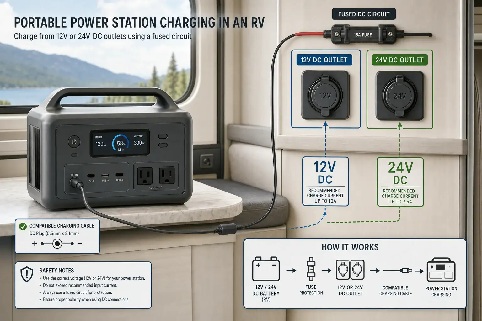
Charging a Portable Power Station From an RV Outlet: 12V, 24V, and Safety Limits

Portable power station charging from 12V and 24V RV outlets with voltage and current limits illustrated

You can charge a portable power station from an RV outlet if the station’s DC input range, cable, connector, and polarity match the outlet.

Charging speed depends on more than whether the outlet is labeled 12V or 24V. The RV circuit’s fuse rating, the portable power station’s DC input limit, cable resistance, alternator output, and battery voltage all affect the available charging watts. A typical 12V outlet is usually slower than a compatible 24V source, but connecting the wrong voltage can damage equipment.

Before using a car charging cable or accessory socket, check both devices rather than relying on plug shape alone. A socket that physically fits may have an unsuitable voltage, polarity, or current capacity. The following guidance explains nominal voltage, expected charging time, troubleshooting signs, and practical safety limits. If “RV outlet” means a 120V AC receptacle, use the power station’s approved AC charger and observe the RV branch circuit rating instead.

1. What Charging From a 12V or 24V RV Outlet Means

A 12V or 24V RV outlet supplies direct current from the vehicle or house electrical system. The portable power station receives that electricity through its DC charging input, where an internal charge controller converts it into the voltage needed by the battery pack.

The voltage labels are nominal, not exact measurements. A 12V lead-acid system may operate near 12V when resting and rise to roughly 13.5–14.7V while charging. A nominal 24V system can operate at approximately twice those values. Lithium-based RV house batteries may have different operating ranges based on their chemistry and charging configuration.

This matters because every portable power station has an accepted input voltage window. A station designed only for a typical 12V vehicle source may reject a 24V supply or suffer damage if it lacks overvoltage protection. Conversely, a wide-range DC input may accept both systems and draw more watts from 24V, subject to current and power limits.

The outlet itself also has limits. Accessory sockets are commonly protected by a 10A, 15A, or similar fuse, but the usable continuous current may be lower because of connector quality, wire length, shared loads, and heat. The lowest limit in the complete charging path determines performance.

2. How Voltage, Current, and Input Limits Control Charging

DC charging power is estimated by multiplying voltage by current: watts equal volts times amps. A 12V source delivering 8A provides about 96W, while a 24V source delivering 8A provides about 192W. Actual battery charging power will be lower after cable and conversion losses.

Three different limits must be considered. The RV circuit has a maximum safe current, the cable and connector have current and voltage ratings, and the portable power station has maximum DC input voltage, current, and wattage. Increasing source voltage does not guarantee faster charging if the station caps input at 100W, for example.

Many power stations reduce input current when voltage falls, components become hot, or the battery approaches full charge. This tapering is normal. Charging may also pause if the RV battery voltage drops below a low-voltage threshold or if the source fluctuates while the engine starts.

Connector type does not establish electrical compatibility. Two cables with similar plugs can be wired differently or intended for different voltage ranges. Use a cable specified for the power station’s input and verify whether it contains a fuse, voltage converter, or identification circuitry.

Typical DC charging relationships. Example values for illustration.
Nominal sourceExample operating voltageExample currentApproximate source powerLikely constraint
12V RV outlet12.5V8A100WSocket, fuse, or wiring
12V with engine charging14.2V8A114WPower station current limit
24V RV outlet25V8A200WPower station voltage or watt limit
24V charging system active28.4V8A227WMaximum accepted input voltage

3. Real-World RV Charging Examples

Charging from a 12V accessory socket

Suppose an RV outlet provides 13V under load and the station draws 8A. Source power is approximately 104W. After conversion losses, the battery may receive around 85–95W. Adding 700Wh could therefore take roughly eight hours rather than the seven hours implied by dividing 700Wh by 100W. Charging slows further near full capacity.

Using a compatible 24V system

If a station accepts up to 30V and 10A, a 25V source at 8A could provide approximately 200W. The same 700Wh addition might take about four hours after accounting for losses and charge tapering. However, this example is safe only when the input, cable, connector, and source are all rated for the actual voltage.

Charging while driving

Charging with the engine running can reduce the chance of draining the RV starter battery, but alternator capacity still matters. Lights, climate controls, refrigerators, and other vehicle loads may already consume much of the available output. A portable power station that repeatedly starts and stops may be responding to voltage sag or a vehicle energy-management system rather than a defective battery.

Charging while parked

A 100W load running for five hours draws approximately 500Wh before losses. That can materially discharge a small RV house battery. The power station’s remaining runtime does not show the condition of the RV battery, so both systems require separate monitoring.

4. Common Mistakes and Troubleshooting Cues

The station does not begin charging: Check whether the outlet is switched, whether the RV battery disconnect is enabled, and whether the source voltage falls within the station’s published DC input range. Also inspect the relevant fuse without replacing it with a higher rating.

Charging starts and stops: Intermittent operation often indicates voltage sag, a loose plug, thermal protection, an overloaded circuit, or an input close to a cutoff threshold. Turn off other loads on the circuit and allow warm connectors or equipment to cool. Persistent cycling should be evaluated rather than ignored.

The displayed input is lower than expected: The advertised maximum input is not a guaranteed rate. A 12V socket, current-limited cable, partially discharged RV battery, or long wire run may prevent the station from reaching that figure. The station can also taper charging as its battery fills.

The fuse blows: A blown fuse can indicate excessive current, a short circuit, damaged wiring, or incorrect polarity. Do not install a larger fuse to keep the circuit operating. Disconnect the load and have recurring failures inspected by a qualified RV technician or electrician.

The plug becomes hot: Mild warmth can occur, but a connector that is painful to touch, discolored, softened, or smells like hot plastic requires immediate disconnection. Worn accessory sockets and poorly fitting plugs create resistance, which produces heat even when current remains below the fuse rating.

A 24V outlet is mistaken for 12V: Plug shape is not proof of voltage. Verify the labeled system voltage and acceptable input range before connecting. If the source can exceed the station’s maximum input voltage while the RV charging system is active, it is incompatible without a properly designed charging device.

5. Essential Safety Limits for RV DC Charging

  • Match the complete voltage range: Compare the RV’s lowest and highest expected voltage with the station’s accepted DC input range, not just nominal labels.
  • Respect the original fuse: The fuse protects the RV wiring. Never substitute a higher-amperage fuse to obtain faster charging.
  • Avoid unknown adapters: An adapter may change plug shape without changing voltage, limiting current, or correcting polarity.
  • Keep connections ventilated: Do not cover the power station, charger, or plug. Keep them away from bedding, paper, direct sun, moisture, and flammable materials.
  • Prevent starter-battery depletion: Use a switched or low-voltage-protected source when appropriate, and do not assume every RV outlet turns off with the ignition.
  • Secure equipment while traveling: Restrain the power station so it cannot fall, block ventilation, strain the cable, or become a projectile.
  • Stop after warning signs: Disconnect the system after repeated fuse failures, burning odors, visible arcing, melted plastic, unusual noise, or battery warnings.

Do not splice into RV wiring, bypass battery-management protections, or create a higher-current circuit without appropriate system design. Permanent charging circuits, alternator-connected chargers, or unfamiliar 24V systems should be assessed and installed by a qualified professional familiar with conductor sizing, overcurrent protection, grounding, and the RV’s electrical architecture.

6. Cable Maintenance, Battery Care, and Storage

Inspect the charging cable and both connectors before long trips. Look for bent contacts, corrosion, cuts, crushed insulation, loose strain relief, and heat discoloration. Dirty or oxidized contacts increase resistance and can cause voltage drop or overheating. Clean only according to the equipment instructions and with all power disconnected.

Store cables loosely coiled in a dry location. Tight bends near a connector can break internal conductors even when the outer insulation appears intact. Protect removable adapters from dust and label them by voltage and intended device to reduce mix-ups.

Keep the RV battery in suitable condition. An aging battery may show normal resting voltage but sag sharply under load, causing unstable charging. During storage, disconnect unnecessary loads as directed by the RV manufacturer and maintain batteries according to their chemistry. Avoid leaving either battery deeply discharged for extended periods.

Portable power stations should generally be stored in a cool, dry location at a manufacturer-recommended state of charge. Periodically check stored units because displays, control circuits, and wireless features may consume energy. Before a trip, test the intended outlet and cable under supervision rather than discovering a problem during travel.

Illustrative charging-time comparison. Example values for illustration.
Energy added to stationAverage battery inputIdeal calculationPractical planning range
300Wh90W3.3 hours3.5–4.5 hours
700Wh90W7.8 hours8–10 hours
700Wh180W3.9 hours4–5 hours
1,000Wh200W5 hours5.5–7 hours

Related guides: Portable Power Stations for RV and MotorhomesHow Long Does It Take to Charge a Portable Power Station?Car Charging Explained: 12V Socket vs DC-DC Charger vs Alternator (Speed + Safety)

7. Practical Takeaways and Specs to Compare

Safe RV charging depends on matching the source, circuit, cable, and power station. Confirm the actual voltage range first, then compare current and watt limits. A 24V source may charge faster than a 12V source, but only when the station explicitly accepts the higher operating voltage. Plan charging time from average input watts rather than the maximum number printed in specifications.

For routine use, monitor the first charging session for unstable input, excessive connector heat, or unexpected RV battery drain. If the outlet cannot safely provide the desired power, use a professionally designed charging solution rather than modifying the socket or increasing its fuse.

Specs to look for

  • DC input voltage range: Look for a clearly stated range such as 11–30V that covers the RV’s resting and active charging voltage; this determines 12V and 24V compatibility.
  • Maximum DC input current: Compare values such as 8A, 10A, or 15A with the outlet and cable rating; the lowest current limit controls charging speed.
  • Maximum DC input watts: Look for a separate limit such as 100–300W; it shows whether higher source voltage can produce faster charging.
  • Included cable rating: Confirm the cable’s supported voltage, current, connector type, polarity, and fuse; physical fit alone does not establish safe operation.
  • Low-voltage cutoff: Look for automatic input shutdown near a configurable or documented threshold; it can help reduce excessive RV battery discharge.
  • Input protections: Overvoltage, overcurrent, reverse-polarity, short-circuit, and thermal protection provide safeguards against common connection problems.
  • Charging display detail: Real-time input watts, estimated time, temperature alerts, and error codes make voltage sag and limited charging easier to diagnose.
  • Operating temperature range: Look for charging limits appropriate for expected RV conditions, often narrower than discharge limits; batteries may not accept a charge safely in extreme heat or cold.
  • Battery capacity in watt-hours: Compare usable capacity with expected charging watts; a larger battery takes longer to replenish from a low-power 12V outlet.

The safest choice is not necessarily the station with the highest input rating. It is the one whose documented voltage range, current demand, cable requirements, and protections align with the RV’s available electrical system.

Frequently asked questions

Can I charge a portable power station from a 12V RV outlet?

Yes, if the power station accepts the outlet’s full operating voltage range and the cable, connector, and polarity are compatible. Charging from a 12V accessory outlet is often limited by the socket fuse, wiring, connector heat, or the station’s DC input rating. Check the equipment documentation before connecting.

Will a 24V RV outlet charge a portable power station faster?

A compatible 24V source can provide more charging power than a 12V source at the same current, but only if the power station accepts the actual 24V operating range. The station’s maximum input watts and amps may still cap charging speed. Never connect a 24V source to equipment rated only for 12V input.

What specifications and features matter when choosing a power station for RV charging?

Compare the station’s DC input voltage range, maximum input current, and maximum input wattage with the RV outlet and circuit ratings. Also verify cable voltage and current ratings, connector polarity, low-voltage cutoff behavior, and protections for overvoltage, overcurrent, reverse polarity, and overheating. A real-time input watt display can help identify voltage sag or a restricted circuit.

Can I use any cigarette-lighter adapter that fits the RV outlet?

No. A plug that fits an accessory socket may still have the wrong voltage rating, polarity, wiring quality, or current capacity for the power station. Use the cable specified for the station whenever possible, and avoid adapters that only change the connector shape without confirming electrical compatibility.

Is it safe to charge a portable power station while driving an RV?

It can be safe when the outlet, wiring, fuse, cable, and power station are correctly matched and the equipment is secured. Monitor the first session for hot plugs, unstable charging, warning messages, or excessive battery drain, and keep the station ventilated. Avoid overloading the alternator or a circuit already serving major RV loads.

Why does my portable power station stop charging from the RV outlet?

Charging may stop because of voltage sag, a loose connection, thermal protection, a low-voltage cutoff, or an overloaded circuit. The station may also reduce or pause input as its battery approaches full charge. Disconnect the system if a plug becomes very hot, a fuse repeatedly blows, or there is a burning odor or visible damage.

Fast AC Charging vs Battery Longevity: Should You Use Turbo Mode Every Time?

Portable power station comparing fast AC turbo charging with slower battery-friendly charging

You do not need to use turbo mode every time; fast AC charging is best reserved for situations when short recharge time matters more than minimizing battery heat and long-term wear. A compatible power station manages its own input limit, charging current, state of charge, and battery temperature, so occasional use of its built-in fast mode is normally expected.

However, routinely charging at maximum input watts can create more heat than a slower setting, especially in a warm room or immediately after a heavy discharge. Heat, sustained high voltage near 100%, and frequent deep charge cycles can all affect battery longevity. The actual impact depends on battery chemistry, thermal management, charge rate, and how long the unit remains full.

For everyday use, a moderate AC charging setting is usually the more conservative choice when there is no deadline. Turbo mode is useful before an outage, trip, or job, but it should not automatically be the default for every recharge.

1. What Turbo AC Charging Means and Why It Matters

Turbo mode, fast AC charging, rapid charging, and boost charging generally describe a power station’s highest available charging setting from a wall outlet. The setting raises AC input power so the battery can recover more energy in less time. Depending on capacity and design, input may range from a few hundred watts to well over 1,000 watts.

The advertised input figure is not the amount of energy that reaches the battery at every moment. Some energy is lost in AC conversion, battery charging, cooling fans, and internal electronics. The battery management system, or BMS, also reduces power when temperature, cell voltage, or state of charge requires it.

Battery longevity is normally expressed as cycle life to a stated remaining capacity. One cycle represents cumulative use equal to 100% of the battery’s rated capacity, not necessarily one connection to an outlet. Two discharges of 50%, followed by two recharges, roughly equal one full cycle.

Fast charging matters because higher current can produce additional internal heat. It may also keep cooling fans running and place more sustained load on charging components. This does not mean turbo mode is inherently unsafe or immediately damaging. It means charging speed is one of several conditions that can influence gradual battery aging.

2. How Charging Speed, Heat, and Battery Chemistry Interact

A useful way to compare charge intensity is the C-rate. Charging a 1,000-watt-hour battery at approximately 1,000 watts is roughly a 1C input before conversion losses and power tapering. Charging the same battery at about 500 watts is roughly 0.5C. Manufacturers may limit the actual cell-level rate below the apparent AC input rate.

Electrical resistance produces heat as current moves through cells and conductors. Higher charging current can therefore raise temperature, although cooling design, ambient conditions, and battery size strongly affect the result. A large battery accepting 800 watts may be under less relative stress than a much smaller battery accepting the same power.

Battery chemistry also matters. Lithium iron phosphate cells are commonly selected for high cycle life and thermal stability, while nickel manganese cobalt formulations often provide greater energy density for a given weight. Neither chemistry is immune to aging. Both generally benefit from avoiding unnecessary heat and extended storage at a completely full or empty state.

Charging is fastest during the main constant-current phase. As the battery approaches full charge, the BMS usually tapers current to prevent cell voltage from rising too far. This is why a claimed short recharge time may apply to a partial range, such as 20% to 80%, rather than sustaining peak input all the way to 100%.

Illustrative charging settingApproximate input for a 1,000 Wh unitLikely behaviorTypical use case
Quiet or slow200–350 WLonger charge time, less fan activity, lower heat potentialOvernight or routine charging
Standard400–700 WBalanced speed, noise, and temperatureGeneral daily use
Turbo or maximum800–1,200 WShortest charge time, more fan activity, greater heat potentialUrgent preparation or short turnaround
Taper near fullFalling below peak inputBMS reduces current as cell voltage risesFinal stage of any charging mode
Example values for illustration.

3. Real-World Examples of When Fast Charging Helps

Preparing for an approaching outage

A power station is at 35%, and severe weather may interrupt utility service within two hours. Turbo mode is practical because the immediate value of stored energy outweighs the small potential benefit of slower charging. Place the unit in a cool, ventilated area and let its built-in controls manage the charge.

Recharging between work sessions

A user has a limited lunch break between periods of running tools or field equipment. Fast AC charging can restore a useful amount of energy during that window. The battery may not need to reach 100%; stopping at 80% or 90% can save time because charging often slows near full.

Routine charging after light use

A unit falls from 80% to 60% after powering a few devices, and it will not be needed until the next day. A standard or quiet charging mode is sufficient. Maximum input provides little practical advantage because the available charging window is long.

Charging after a heavy, hot discharge

A power station has just operated near its continuous output limit in warm weather. Starting turbo charging immediately may add charging heat to an already warm battery. If there is no urgent need, allow the unit to return to a normal operating temperature, following its manual, and then use a moderate charging setting.

Daily backup cycling

When a unit is charged and discharged every day, operating habits have more opportunity to affect long-term capacity. Moderate charging, avoiding unnecessary time at 100%, and reducing heat exposure are generally more meaningful than optimizing an occasional recharge.

4. Common Charging Mistakes and Troubleshooting Cues

Assuming the displayed input must equal the advertised maximum: Peak AC input may appear only within a suitable temperature and state-of-charge range. Household voltage, enabled settings, system loads, and power tapering can also reduce the display.

Running appliances while measuring recharge time: Pass-through operation can make charging appear slower because part of the wall power supports connected loads. Compare charging performance with outputs turned off if the manual permits normal charging in that condition.

Blocking cooling airflow: Placing the unit against a wall, inside a cabinet, or on a soft surface can restrict vents. The BMS may reduce input power, fans may become louder, and internal temperature may rise.

Charging in extreme temperatures: Cold conditions can trigger reduced current or a low-temperature charging lockout. High ambient temperatures can also cause throttling. Move the unit to a dry environment within its specified charging range rather than trying to defeat the protection.

Expecting peak power near 100%: Falling input above roughly 80% to 90% is often normal charge tapering. A sudden reduction earlier in the cycle may instead indicate high temperature, an active input limit, unstable AC power, or simultaneous output loads.

Ignoring unusual behavior: Repeated shutdowns, error codes, abnormal odor, swelling, crackling, or excessive heat are not routine signs of fast charging. Stop use, disconnect the charging source if it is safe to do so, move away from combustible materials, and follow the manufacturer’s service guidance.

5. Safety Basics for High-Power AC Charging

Use the supplied or specifically approved AC charging cable and connect it directly to a properly grounded outlet when required by the product. High-input charging can draw substantial current for an extended period. Loose receptacles, damaged cords, overloaded power strips, and undersized extension cords can overheat.

  • Inspect the plug, cable, inlet, and outlet for damage or unusual discoloration before charging.
  • Keep vents clear and leave space around the power station for airflow.
  • Charge on a stable, dry surface away from heaters, direct sun, moisture, and combustible clutter.
  • Do not cover the unit to reduce fan noise.
  • Do not open the enclosure, modify the battery, bypass temperature controls, or replace protective components.
  • Stop charging if the unit displays a persistent fault or develops an unusual smell, deformation, smoke, or extreme surface heat.

Some high-capacity models can approach the practical load limit of a household branch circuit, particularly when other appliances share it. If an outlet becomes hot, a breaker trips repeatedly, or the installation is uncertain, stop using that circuit and consult a qualified electrician. Do not improvise a connection to a home electrical panel or attempt to backfeed household wiring.

6. Maintenance and Storage Habits That Support Battery Life

Charging mode is only one part of battery care. Temperature and storage state of charge often matter more than whether turbo mode was used occasionally. Store the power station in a cool, dry location within the specified storage temperature range. Avoid leaving it in a hot vehicle, direct sunlight, or an unconditioned space that regularly experiences extreme heat.

For extended storage, many lithium battery products are best kept at a partial charge rather than continuously at 100% or completely empty. A range around 40% to 70% is a common example, but the product manual should take priority because standby consumption, cell balancing, and storage recommendations vary.

Check the battery periodically because internal electronics can slowly consume energy while the unit is off. Recharge before it becomes deeply depleted. If the power station is maintained for emergency readiness, keeping it near full may be operationally justified even though partial-charge storage can be gentler on the cells. Reliability during an outage may be more important than maximizing theoretical cycle life.

Keep firmware current through supported methods when updates address charging control or battery reporting. Clean exterior vents without opening the enclosure, and periodically inspect cords and connectors. Capacity estimates can drift, so an occasional normal discharge and full recharge may help some battery gauges recalibrate when the manual recommends it; this process does not restore lost battery capacity.

SituationPractical charge targetCharging approachMain reason
Frequent daily useAbout 80%–90% when full capacity is unnecessarySlow or standardReduces time spent at maximum state of charge
Emergency readinessNear 100%Any suitable modePrioritizes available runtime
Storage for several monthsAbout 40%–70%Standard, then power downLimits prolonged high or very low charge
Immediate reuseEnough for the next loadTurbo if turnaround is limitedPrioritizes charging speed
Example values for illustration.

Related guides: AC Charging Heat & Fan Noise: Why It Happens and How to Reduce It SafelyTemperature Limits Explained: Safe Charging/Discharging Ranges and What Happens Outside ThemBest Storage Charge Percentage: 40% vs 60% vs 80% (What Battery Chemistries Prefer)

7. Practical Takeaways and Specs to Look For

Use turbo mode when time matters, not simply because it is available. Occasional fast AC charging within the unit’s stated operating conditions is a normal use case. For routine charging with several hours available, a slower or standard setting can reduce noise and heat while placing less demand on the outlet.

A practical strategy is to reserve maximum charging for outage preparation, travel days, work breaks, and other short turnaround periods. After heavy discharge or hot operation, let temperature normalize when possible. Avoid keeping the unit at 100% for long periods unless readiness requires it, and do not intentionally run the battery to zero for every cycle.

Specs to look for

  • Adjustable AC input power: Look for multiple settings or a user-selectable range, such as 200–1,200 watts; this allows charging speed, fan noise, and heat to be matched to the available time.
  • Full recharge time: Compare stated times from 0% to 100% as well as partial-charge claims; full-range figures better reflect tapering near maximum state of charge.
  • Battery chemistry: Check whether the unit uses lithium iron phosphate or another lithium formulation and review its stated cycle-life conditions; chemistry influences weight, energy density, and expected longevity.
  • Cycle-life rating: Look for a rating such as 2,000–4,000 cycles to about 80% remaining capacity, including the test conditions; this makes longevity claims easier to compare.
  • Thermal management: Look for temperature sensors, active cooling, low-temperature charge protection, and high-temperature throttling; these features help keep cells within a suitable operating range.
  • Charge limit controls: A selectable maximum state of charge, such as 80%, 90%, or 100%, can reduce time spent completely full when maximum runtime is unnecessary.
  • AC input limit: Check both maximum watts and approximate current draw; this helps determine whether the charging load is appropriate for the intended household circuit.
  • Charging temperature range: Look for a clearly stated range, often narrower than the discharge range; charging outside suitable temperatures may be blocked or reduced.
  • Pass-through power behavior: Check whether outputs remain available during AC charging and whether input power is shared with connected loads; this affects actual recharge time and heat.

The best balance is situational: choose fast charging for urgency and moderate charging for routine use. Battery-friendly habits should focus on controlling heat, avoiding unnecessary extremes of charge, providing ventilation, and following the power station’s specified charging and storage conditions.

Frequently asked questions

Does fast AC charging reduce battery life?

Fast AC charging can contribute to additional battery wear over time because higher charging current may create more heat. Occasional use within the product’s specified temperature and charging limits is generally an intended operating condition. For routine charging when time is available, a moderate setting is usually the more conservative option.

Is it better to charge a power station to 80% or 100%?

Charging to 80% or 90% can reduce the amount of time a lithium battery spends at a high state of charge, which may be helpful for frequent-use situations. Charging to 100% is appropriate when maximum runtime is needed, such as before travel or possible utility outages. The product manual and any available charge-limit setting should guide the choice.

What specifications and features matter most for battery-friendly AC charging?

Useful features include adjustable AC input power, selectable charge limits, temperature monitoring, active cooling, and low- and high-temperature charging protection. Also compare the battery chemistry, cycle-life rating, stated charging temperature range, and full recharge time rather than relying only on a peak input-watt figure. These details provide a clearer view of charging flexibility and expected long-term use.

Why is my power station charging slower than its advertised maximum input?

A lower displayed input can be normal when the battery is nearing full charge because the charging system reduces current to protect cell voltage. Temperature, household voltage, enabled input limits, connected output loads, and restricted airflow can also lower charging power. Check the selected mode and operating conditions before assuming there is a fault.

Is it safe to use turbo charging on a regular household outlet?

It can be safe when the power station, charging cable, and outlet are in good condition and the circuit can support the sustained load. Use a properly grounded outlet when required, keep the unit ventilated, and avoid damaged cords, overloaded power strips, or undersized extension cords. Stop charging if the outlet or plug becomes unusually hot, a breaker repeatedly trips, or the unit shows a persistent fault.

Should I let a hot power station cool down before charging it?

If the unit has just been heavily discharged or used in a warm environment, allowing it to return to a normal operating temperature can help avoid adding charging heat to an already warm battery. Follow the manufacturer’s stated charging temperature range and built-in protection messages. Use turbo mode immediately only when the need for a fast recharge outweighs the benefit of waiting.

Can You Charge a Portable Power Station From an EV Charger? What Is Realistic?

Portable power station next to an EV charger showing compatible charging considerations

Yes, you can charge some portable power stations from an EV charger, but only when the charger type, voltage, adapter, and the station’s AC input are compatible. In real life, it is not as simple as plugging any power station into any EV charging handle. The limiting factors are usually the input limit of the power station, whether the EV charger is Level 1, Level 2, or DC fast charging, and whether a safe, rated adapter or built-in EV charging port exists.

The realistic answer is that standard wall-outlet charging is still the easiest method for most units. A Level 2 charger can be useful for certain larger power stations that accept 240-volt AC or have a compatible EV charging accessory, but it will not make a small unit charge at EV speeds. DC fast charging is generally not realistic for typical portable power stations because it uses high-voltage communication and battery management systems designed for vehicles, not small backup batteries.

What it means to charge a portable power station from an EV charger

Charging a portable power station from an EV charger means using electricity from equipment designed for electric vehicles to recharge a battery generator. The important distinction is that an EV charging station is not always delivering the same kind of power. Some chargers supply AC power that the vehicle converts internally. Others supply high-voltage DC power directly to an EV battery under tight electronic control.

Most portable power stations are designed around a few common charging inputs: a regular AC wall plug, solar DC input, vehicle 12-volt input, and sometimes higher-voltage AC or DC inputs. An EV charging connector is not the same as a household outlet. It may require signaling before it energizes, it may deliver 240 volts, and it may use connector designs that a portable power station cannot accept without a purpose-built adapter or inlet.

This matters because charging speed is controlled by the receiving device, not by the largest number printed on the EV charger. A Level 2 EV charger may be capable of several kilowatts, but a power station with a 600-watt AC input will still draw roughly 600 watts, assuming the voltage and connection are compatible. If the station can only accept 120 volts, connecting it to a 240-volt source is not a safe workaround.

How EV chargers and power station inputs actually work

Level 1 EV charging normally uses 120-volt AC power from a standard outlet. In that case, the portable power station is not really using the EV charger itself; it is using a normal household-style circuit. If the power station’s AC charging cord fits the outlet and the circuit can support the load, this is usually the most straightforward option.

Level 2 EV charging in North America is commonly 240-volt AC. The EV charging equipment communicates with the vehicle and tells it how much current is available. A portable power station cannot assume that role unless it has a compatible EV charging input or a properly rated adapter that provides the required signaling and a suitable receptacle. Even then, the power station must be rated for the voltage and current it will receive.

DC fast charging is different. It bypasses the vehicle’s onboard AC charger and transfers high-voltage DC directly to the EV battery after a communication handshake. Typical portable power stations are not built to accept that kind of input. Unless a power station system is specifically engineered for DC fast charging, it should be considered incompatible.

The practical charging time depends on battery capacity and input watts. A 1,000 watt-hour unit charging at 500 watts may take a little over two hours in idealized math, but real charging takes longer due to conversion losses, tapering near full, temperature management, and system overhead. A larger 3,000 watt-hour unit may benefit more from a higher-power input, but only if the unit is designed to accept it.

EV charging sourceWhat the power station needsRealistic expectation
Standard 120-volt outlet near an EV chargerNormal AC charging cord and enough circuit capacityUsually practical, but limited by the station’s AC input
Level 1 EV cordCompatible outlet access, not the EV vehicle connectorSimilar to household outlet charging
Level 2 AC chargerBuilt-in compatible inlet or properly rated EV-to-AC adapter, plus 240-volt support if applicablePractical only for some larger or specially equipped units
DC fast chargerSpecialized high-voltage DC charging architectureGenerally not realistic for typical portable power stations
EV charger compatibility depends on input type, voltage, and the receiving device. Example values for illustration.

Real-world examples of what is realistic

Consider a compact 500 watt-hour power station with a 300-watt AC input. Even if you find a Level 2 charger capable of many kilowatts, that small unit cannot use that extra capacity. If it charges through a 120-volt wall outlet, a full charge may take roughly two hours or more depending on losses and charge taper. A Level 2 source would not help unless the unit specifically supports it, and many compact models do not.

Now consider a mid-size 1,000 to 1,500 watt-hour power station with a 1,000-watt or 1,500-watt AC input. If it can accept the available voltage, it may recharge much faster from a high-power AC source than from a low-current outlet. However, the connector must still be correct, the adapter must be rated, and the charging site must allow that use. The EV charger does not automatically turn into a universal generator outlet.

A large power station or modular backup battery with a 240-volt AC input is the most realistic candidate for Level 2 charging. Some systems are designed to accept higher AC charging rates, such as 3,000 watts or more. In that scenario, a compatible Level 2 source may be useful when a normal outlet would be slow. The key is that the feature must be built into the system or supported by an approved accessory.

At public EV charging locations, the practical issues are often not electrical at all. The charger may require vehicle-style activation, the connector may not energize without the correct handshake, the site may prohibit non-EV use, or the power station and cable setup may create a trip hazard. Even when the electrical theory works, the real-world setting may not.

Common mistakes and troubleshooting cues

The most common mistake is assuming that a charger’s maximum output determines the power station’s charging speed. It does not. The station’s input limit is the ceiling. A unit rated for 800 watts of AC input will not safely draw 3,000 watts just because the source can supply it.

Another mistake is confusing connector shape with compatibility. A physical adapter is not enough if it does not handle voltage, current, grounding, and EV signaling correctly. A mismatch can result in no charging, tripped protection, overheating, or damaged equipment.

If the power station does not charge, start with the basic cues. Check whether the charging source is energized, whether the station displays input watts, whether the EV charger has completed its activation process, and whether the adapter is rated for the voltage and current involved. If the station shows an input error or repeatedly starts and stops, that can indicate an unsupported voltage, unstable power, overheating, or a protection circuit doing its job.

If charging is much slower than expected, compare the displayed input watts to the station’s rated input. A power station may reduce input when the battery is nearly full, when temperatures are high or low, or when the unit is running heavy output loads at the same time. Running appliances while charging can also make the net battery gain look slower because some incoming power is being used immediately.

Do not try to solve compatibility problems by bypassing protections, altering plugs, opening devices, or forcing a nonmatching connector. If the documentation does not clearly support the charging method, treat it as unsupported. For permanent high-power charging setups, have a qualified electrician evaluate the circuit, receptacle, breaker capacity, grounding, and local code requirements.

Safety basics for EV charger use with portable power stations

The safest approach is to use only charging methods that the power station is designed to accept. That means staying within the listed input voltage range, frequency, current, and wattage. A 120-volt-only AC input should not be connected to 240 volts. A solar input should not be connected to an AC EV charger. A DC fast charger should not be adapted casually to a portable battery.

Use cables and adapters that are rated for the expected load and environment. High charging current creates heat, especially at connectors. Loose plugs, undersized cords, damaged insulation, or wet conditions increase risk. If a plug, cable, or adapter becomes hot to the touch, smells unusual, or shows discoloration, stop using it and have the setup inspected.

Grounding and ground-fault protection also matter. EV charging equipment is designed with safety checks, and many portable power stations include their own protective electronics. These systems may not behave as expected when combined through unsupported adapters. A charging setup that repeatedly trips a breaker, ground-fault device, or charger fault should be treated as a warning, not an annoyance to work around.

Location matters, too. Charge on a stable surface with ventilation around the power station. Keep cords out of walkways, avoid standing water, and protect the unit from rain unless it is specifically rated for that environment. Portable power stations contain lithium batteries and power electronics that should not be exposed to conditions beyond their design limits.

Maintenance and storage when using high-power charging sources

Frequent high-power charging is convenient, but it can create more heat than slower charging. Heat is one of the main factors that affects lithium battery aging. If the power station allows adjustable charging speed, using a lower input setting during routine charging can be gentler, while saving maximum input for times when speed matters.

For storage, avoid leaving the power station completely full or completely empty for long periods unless the manual specifically recommends it. A moderate state of charge is commonly preferred for lithium battery storage. Check the unit periodically because standby electronics and battery management systems can slowly reduce charge over time.

Keep charging ports clean and dry. Dust, corrosion, or bent contacts can cause poor connections and heat buildup. Inspect AC cords, EV adapters, and extension cords before use. Replace damaged accessories rather than trying to repair overmolded plugs or sealed connectors.

If the unit has been stored in very cold or hot conditions, let it return to an acceptable operating temperature before charging. Many power stations will block charging outside their safe temperature range. That protection helps prevent battery damage, so repeated temperature-related charging errors should be addressed by changing the charging environment, not by trying to override the device.

Use patternBetter habitWhy it matters
Routine home chargingUse a moderate input setting when availableReduces heat during non-urgent charging
Occasional fast chargingUse only rated high-power inputs and adaptersKeeps voltage and current within design limits
Long-term storageStore around a moderate charge level and check periodicallyHelps limit deep discharge and battery stress
Outdoor or public chargingKeep equipment dry, ventilated, and away from foot trafficReduces electrical, heat, and trip hazards
Charging habits affect convenience, heat, and battery life. Example values for illustration.

Related guides: Input Limits (Volts/Amps/Watts) Explained: How Not to Damage Your UnitFast Charging Explained: What “AC Input” and “DC Input” Speeds MeanHow Long Does It Take to Charge a Portable Power Station?

Practical takeaways and specs to look for

The realistic answer is that most portable power stations can charge from a normal AC outlet, some can charge from certain Level 2 EV charging setups, and typical units cannot use DC fast chargers. The deciding factors are not the size of the EV charger alone, but the input design of the power station and the safety of the connection between them.

If you want EV-charger compatibility, look for it before you buy. Do not assume it can be added later with a generic adapter. A power station intended for high-power AC charging should clearly state the supported voltage range, maximum input watts, connector type, and accessory requirements. For any fixed receptacle or high-current charging location, a qualified electrician can help confirm that the circuit is appropriate.

Specs to look for

  • AC input voltage range: Look for clear support for 120 volts, 240 volts, or both; this determines whether Level 2 AC charging is even possible.
  • Maximum AC input watts: Look for values such as 600, 1,500, or 3,000 watts; this sets the real charging speed ceiling regardless of charger capacity.
  • EV charging compatibility: Look for a built-in compatible inlet or listed EV charging accessory; this matters because EV connectors often require signaling, not just plug adaptation.
  • Adjustable charge rate: Look for selectable low, medium, and high input settings; this helps balance fast charging with heat and battery longevity.
  • Battery capacity in watt-hours: Look for a size that matches your loads, such as 500 to 3,000 watt-hours; capacity determines how much energy you store and how long charging may take.
  • Input temperature range: Look for a stated charging temperature window; lithium batteries may limit or block charging when too hot or too cold.
  • Pass-through charging behavior: Look for clear guidance on using outputs while charging; this affects runtime planning and how fast the battery actually refills.
  • Cable and adapter ratings: Look for matching voltage, amperage, grounding, and outdoor-use ratings when applicable; weak accessories can become the unsafe part of an otherwise capable system.

For most people, the best plan is simple: use a regular outlet when time allows, use higher-power AC charging only when the power station is designed for it, and treat DC fast charging as outside the scope of typical portable power stations. EV charging can be useful in the right setup, but compatibility and input limits decide what is realistic.

Frequently asked questions

Can any portable power station charge from an EV charger?

No. Only power stations with compatible input voltage, connector support, and charging electronics can use an EV charging source safely. Many units are limited to standard AC wall charging or low-voltage DC inputs. If the manual does not explicitly support EV-style charging, assume it is not compatible.

What specs matter most if I want to charge a portable power station from an EV charger?

The most important specs are the AC input voltage range, maximum input watts, and whether the unit supports a compatible EV charging accessory or inlet. You should also check the charging temperature range and any adapter or grounding requirements. These details determine whether the setup is possible and how fast it will charge.

Is it safe to use a public EV charger for a portable power station?

Only if the power station and adapter are specifically designed for that use and the charging site allows it. Public chargers may require vehicle-style communication before energizing, and unsupported adapters can create electrical or trip hazards. When in doubt, use a standard outlet or a charging method listed by the manufacturer.

What is the most common mistake people make with EV charging and power stations?

The biggest mistake is assuming the charger’s maximum output controls the charging speed. In reality, the power station’s input limit is the ceiling, so a large EV charger will not make a small unit charge faster than it is designed to accept. Connector shape alone also does not guarantee compatibility.

Can a Level 2 charger make my power station charge faster than a wall outlet?

Sometimes, but only if the power station supports 240-volt AC input or a compatible EV charging accessory. If the unit is limited to 120 volts or a lower wattage input, the Level 2 source will not increase speed beyond that limit. The station’s own charging design is what matters most.

Why does my power station stop charging or show an error with an EV charger?

That usually means the voltage, signaling, grounding, or adapter setup is not supported. It can also happen if the charger has not completed its activation process or if the power station is protecting itself from heat or an out-of-range input. Recheck the manual and the rated input specifications before trying again.

140W vs 240W USB-C Output: Which Power Station Feature Actually Matters?

Portable power station USB-C output comparison for 140W and 240W charging

A 240W USB-C output matters only if your device can actually accept more than 140W and the power station supports the right USB Power Delivery profile; otherwise, port quality, runtime, and total output capacity usually matter more.

For most phones, tablets, small laptops, cameras, and handheld devices, a 140W USB-C port is already more than enough. The difference becomes important for power-hungry laptops, mobile workstations, some battery chargers, and setups where you want faster charging without using an AC adapter. Search terms such as PD profile, input limit, charging speed, output watts, runtime, and pass-through charging all point to the same issue: the number printed beside the USB-C port is only one part of the charging equation.

The practical goal is not to buy the highest USB-C watt rating on paper. It is to match the power station output, the device input limit, and the cable capability so the system can deliver stable power safely and efficiently.

What 140W and 240W USB-C Output Mean on a Power Station

USB-C output wattage describes the maximum amount of power a port can provide to a compatible device. A 140W USB-C port can deliver up to about 140 watts under the right conditions. A 240W USB-C port can deliver up to about 240 watts when the device, cable, and power station all support the required charging mode.

The key phrase is up to. A 240W port does not force 240 watts into every device. A phone may draw 15W to 30W, a tablet may draw 20W to 45W, and a typical laptop may draw 45W to 100W. If the device requests only 65W, both a 140W port and a 240W port may charge it at the same speed.

USB-C output matters because it can replace a bulky AC power brick. Charging through DC-based USB-C is often more efficient than converting battery power to AC and then back to DC inside a laptop charger. That efficiency can slightly improve runtime, reduce heat, and free up AC outlets for appliances that truly need them.

However, USB-C wattage is not the same as total power station capability. A unit may have a large battery but limited USB-C ports, or it may have a strong USB-C port but a small battery. The feature that actually matters depends on what you plan to charge and for how long.

How USB-C Power Delivery Actually Works

Modern high-wattage USB-C charging relies on USB-C Power Delivery, often shortened to USB PD. Instead of sending maximum power immediately, the power station and device negotiate a voltage and current combination. This is why the PD profile matters as much as the headline wattage.

Power is calculated as volts multiplied by amps. A 100W USB-C connection might use 20 volts at 5 amps. Higher outputs such as 140W or 240W generally require newer extended power range profiles, higher voltages, and properly rated cables. If one part of the chain does not support the needed profile, charging falls back to a lower level.

The cable is a common limiting factor. Some USB-C cables are designed only for basic charging. Others are rated for higher current and include an electronic marker that identifies their capability to the charger and device. Without the right cable, a 240W port may behave like a lower-wattage port.

The device also sets the ceiling. A laptop with a 96W input limit will not suddenly accept 140W or 240W. A power station can offer more, but the device decides what it requests. This is why two people can use the same power station and see very different charging speed results.

FeatureTypical 140W USB-C OutputTypical 240W USB-C OutputWhy It Matters
Best fitPhones, tablets, many laptops, compact work setupsHigh-power laptops and demanding USB-C equipmentHigher wattage helps only when the device can use it
NegotiationRequires compatible USB PD profileRequires higher USB PD profile and compatible cableUnsupported profiles reduce actual charging speed
Cable sensitivityModerate to highHighThe cable can cap charging below the port rating
Runtime impactLower drain at maximum outputFaster battery drain at maximum outputHigher output can empty the power station sooner
Example values for illustration.

Real-World Examples: When 140W Is Enough and When 240W Helps

For a smartphone, the difference between 140W and 240W is usually irrelevant. Most phones draw far less than 140W. The charging speed will be limited by the phone, its battery temperature, and its supported charging protocol. In this case, a reliable 60W or 100W USB-C port may already exceed what the phone needs.

For tablets and compact laptops, 140W is often more than adequate. Many everyday laptops work well at 45W, 65W, 90W, or 100W. Even a laptop that ships with a 100W charger may not draw that continuously; it may peak briefly, then settle lower once the battery fills or workload changes.

A 140W port becomes especially useful when you want to charge a laptop directly from the power station without occupying an AC outlet. It can also help maintain charge while doing moderate work, such as web browsing, video calls, photo management, or document editing. In these uses, 240W usually does not improve anything unless the laptop is designed for it.

A 240W USB-C port is more relevant for high-performance laptops, mobile workstations, portable monitors combined with laptop charging, drone battery chargers that support high-power USB-C, or professional field kits that need faster turnaround. It can reduce charge time if the receiving device supports high input and if the station can maintain the output without overheating or throttling.

There is also a battery capacity tradeoff. Drawing 240W from a power station can drain a small unit quickly. For example, a 500 watt-hour power station running a true 240W load will not run for two full hours after conversion losses and reserve limits. Higher output is useful, but capacity determines how long that output is useful.

Common Mistakes and Troubleshooting Cues

The most common mistake is assuming a device will charge at the number printed on the power station. If a laptop charges at 65W from a 240W port, that does not automatically mean the power station is defective. It may mean the laptop requested 65W, the cable is limiting the connection, or the battery management system reduced charging because the device is warm or nearly full.

Another mistake is using a low-rated USB-C cable with a high-wattage port. If the charging wattage seems stuck at a lower level, the cable should be one of the first things to check. A cable intended for light phone charging may not support high current. Cable length and build quality can also affect stability, especially at higher wattage.

Users also confuse output limits with input limits. A power station may have a 140W or 240W USB-C output for charging devices, but its own input limits may be different. The input limit controls how fast the power station can be recharged through USB-C, while the output limit controls how fast it can charge other devices.

Shared port limits can cause surprises. Some power stations advertise multiple USB-C ports, but the total USB output may be capped when several ports are used at once. A single port might provide 140W by itself, then drop to 100W or 65W when another port is active. This is normal if the design uses a shared power budget.

Troubleshooting cues include unexpected slow charging, charging that starts and stops, a laptop that drains while plugged in under heavy load, or a cable that gets unusually warm. These signs point to a mismatch among device demand, PD profile, cable rating, or the power station output budget.

Safety Basics for High-Wattage USB-C Charging

High-wattage USB-C charging is designed to negotiate power automatically, but it still deserves basic caution. Use cables rated for the wattage you expect, keep connectors clean and fully seated, and avoid using damaged, kinked, or frayed cables. A loose connector can create heat and intermittent charging.

Do not try to bypass USB-C protections, modify battery packs, open the power station, or adapt connectors in a way that defeats the normal negotiation process. The safety advantage of USB-C Power Delivery comes from communication between the charger and device. Improvised adapters can remove that protection and create overheating or failure risks.

Heat is another practical safety factor. Charging a laptop at high wattage while the power station is in direct sun, a hot vehicle, or a covered compartment can trigger thermal limits. Good ventilation helps the internal electronics maintain stable output. If the station reduces output or shuts down, let it cool and reduce the load rather than repeatedly restarting it.

For home backup use, remember that USB-C ports are for device charging, not for wiring a power station into household circuits. Any connection to a home electrical system should be handled with appropriate equipment and a qualified electrician. This is separate from normal portable use such as charging laptops, phones, radios, medical accessories, or camera batteries.

Maintenance and Storage Habits That Preserve USB-C Performance

USB-C output performance depends on healthy electronics, clean ports, and a battery that can support the requested load. Store the power station in a dry, moderate-temperature location. Extreme heat accelerates battery aging, while deep cold can reduce available output temporarily.

Keep USB-C ports free from dust, grit, and moisture. A port cover can help during camping, field work, or garage storage. If debris is visible, use gentle external cleaning only; do not insert metal objects into the port. Damaged pins or contamination can cause unreliable negotiation and slow charging.

Battery state of charge also matters. For long-term storage, many lithium-based power stations prefer being stored partially charged rather than completely full or completely empty. Check the unit periodically and recharge as needed. A deeply discharged battery may limit output or require a recovery charge before normal use.

Update settings only through normal user controls if the device provides them. Some power stations have eco modes, screen-off timers, USB always-on settings, or app-based options that affect port behavior. These settings can be useful, but they should not be confused with the electrical capability of the USB-C port itself.

SymptomLikely CausePractical Check
Charging stays below expected wattageDevice input limit or cable limitCompare the device input rating and use a high-wattage USB-C cable
Charging starts and stopsLoose connector, heat, or unstable negotiationReseat the cable, reduce load, and improve ventilation
Port output drops when another device is connectedShared USB power budgetCheck single-port and multi-port output ratings
Power station drains faster than expectedHigh sustained wattage and conversion lossesEstimate runtime from watt-hours, not just port rating
Example values for illustration.

Related guides: Portable Power Station Basics: Outputs, Inputs, and What the Numbers MeanUSB-C Power Delivery (PD) Explained for Portable Power StationsInput Limits (Volts/Amps/Watts) Explained: How Not to Damage Your Unit

Practical Takeaways: Which Feature Actually Matters?

The most important feature is not automatically 240W USB-C. The feature that matters is the highest stable USB-C output your actual devices can use, supported by the right PD profiles, enough battery capacity, and clear shared-output ratings. For many users, a well-implemented 140W port is more useful than a poorly documented 240W port.

Choose 140W USB-C output when your main devices are phones, tablets, cameras, portable monitors, and mainstream laptops. It is also a strong fit if you value efficiency and want to avoid using AC adapters for everyday electronics. Choose 240W USB-C output when you have a high-power laptop or specialized USB-C equipment that specifically supports higher input and benefits from faster charging.

Runtime still matters. A high-output port on a small battery can be useful for short bursts but less useful for all-day work. If you plan to power a laptop through long sessions, compare watt-hours, expected device draw, and whether you will also run lights, routers, fans, or other devices at the same time.

Specs to look for

  • Single-port USB-C output: Look for 100W, 140W, or 240W ratings that match your highest-demand device; this determines whether you can charge directly without an AC adapter.
  • Supported PD profiles: Look for clear voltage and current options such as 20V, 28V, 36V, or 48V examples; this matters because the device and power station must agree on a profile.
  • USB-C cable rating: Look for cables rated for the wattage you intend to use, such as 100W, 140W, or 240W; the wrong cable can cap charging or cause dropouts.
  • Total USB output budget: Look for a combined rating when multiple USB ports are used, such as 100W plus 60W or 140W shared; this prevents surprises when charging several devices.
  • Battery capacity: Look for watt-hour capacity that fits your runtime needs, such as 300Wh for light electronics or 700Wh and above for longer laptop sessions; output wattage does not indicate duration.
  • AC inverter rating: Look for continuous watts and surge watts separately, especially if you also run AC devices; USB-C output does not replace the need for adequate inverter capacity.
  • USB-C input capability: Look for input limits such as 60W, 100W, or higher if you plan to recharge the power station by USB-C; input is separate from output.
  • Thermal and overload protection: Look for documented protections against overheating, overcurrent, and short circuits; stable high-wattage charging depends on safe power management.
  • Pass-through charging behavior: Look for clear guidance on using USB-C output while the station is recharging; this matters for desk setups, travel days, and backup workflows.

In short, 240W USB-C is a valuable premium feature for the right equipment, but it is not automatically better for every user. A balanced power station with the right USB-C output, sufficient capacity, transparent port limits, and compatible cabling will usually deliver a better real-world experience than a unit chosen only for the biggest number beside one port.

Frequently asked questions

Is 140W USB-C output enough for most laptops?

Yes, for many everyday laptops 140W is more than enough. A lot of models charge at 45W, 65W, 90W, or 100W, so the device often sets the real limit. If your laptop does not support higher input, a 240W port will not make it charge faster.

When does 240W USB-C output actually matter?

240W matters for devices that can accept very high USB-C input, such as some performance laptops and specialized equipment. It can also help when you want faster charging without using an AC adapter. If the device only requests lower power, the extra wattage will not be used.

What specs matter more than the watt rating alone?

The most important specs are the supported USB Power Delivery profiles, the device input limit, the cable rating, and the total USB output budget. Battery capacity also matters because it determines how long the power station can sustain the load. A higher watt number is only useful when the whole chain supports it.

What is a common mistake people make with high-wattage USB-C charging?

A common mistake is assuming the port rating guarantees that speed for every device. Another frequent issue is using a cable that cannot support the needed wattage, which can cap charging or cause dropouts. Shared-port limits can also reduce output when multiple devices are connected.

Is high-wattage USB-C charging safe?

It is generally safe when the power station, device, and cable all support the same charging standard. Use properly rated cables, keep connectors in good condition, and avoid damaged or improvised adapters. Heat management also matters, so good ventilation helps maintain stable charging.

Why is my device charging slower than the port rating?

The device may have a lower input limit than the port can provide. The cable may also be limiting the connection, or the device may reduce charging because it is warm or nearly full. In some cases, the power station shares output across multiple ports, which lowers the available wattage.

Bidirectional USB-C Charging on Power Stations: What It Means in Real Use

Portable power station using bidirectional USB-C charging with a laptop and phone

Bidirectional USB-C charging means the same USB-C port on a power station can either receive power to recharge the station or send power out to run or charge other devices.

In real use, that sounds simple, but the results depend on the USB-C PD profile, input limit, output watts, cable rating, and the connected device. A port labeled USB-C does not automatically mean fast charging in both directions. Some ports provide only low-power output, some accept high-power input, and some can do both but not at the same time.

For portable power stations, bidirectional USB-C can reduce the number of adapters you carry, help with laptop charging, and provide a cleaner backup setup. It can also create confusion when a station charges slowly, refuses to charge a laptop, or switches direction unexpectedly. Understanding the key specs makes troubleshooting easier and helps you compare models without relying on marketing terms.

What bidirectional USB-C charging means and why it matters

On a power station, bidirectional USB-C charging refers to a USB-C port that supports power flow in two directions. In input mode, the port receives power from a USB-C wall charger, vehicle adapter, or another compatible source to recharge the power station battery. In output mode, the same port sends power to a phone, tablet, laptop, camera battery charger, small router, or other USB-C device.

The practical value is convenience. Instead of packing a separate AC charger or using the station’s AC inverter for every device, you may be able to plug a USB-C cable directly into the station. This can improve efficiency because DC-to-DC charging usually avoids the extra conversion losses of running an AC outlet just to power a USB-C laptop charger.

It also matters for backup planning. A power station with a strong bidirectional USB-C port can recharge from compact USB-C chargers when solar or the main AC adapter is not available. It can also keep modern electronics running without occupying the larger AC outlets. For travel, remote work, emergency communications, and light camping, that single port can become one of the most-used connections on the unit.

The important catch is that bidirectional does not define the wattage. A 30-watt bidirectional port and a 100-watt bidirectional port are very different in real use. The label tells you power can flow both ways; the specifications tell you whether it will be fast enough for your devices.

How USB-C power delivery works on power stations

Most higher-power USB-C charging uses USB Power Delivery, often shortened to USB-C PD. Instead of sending one fixed voltage, the charger and device communicate and agree on a supported voltage and current combination. These combinations are commonly called PD profiles. A phone might request a lower profile, while a laptop may request 20 volts at several amps.

The power station’s USB-C controller decides whether the port acts as a source, a sink, or in some designs either role depending on what is connected. As a source, it offers power to external devices. As a sink, it accepts power from a charger. The connected charger, cable, and device all affect the final result.

Wattage is the product of voltage and current. For example, 20 volts at 5 amps equals 100 watts. Many USB-C cables can safely carry up to 3 amps, while higher-current charging often requires an electronically marked cable designed for 5 amps. If the cable cannot support the requested current, the system may fall back to a lower wattage.

Some power stations have separate limits for USB-C input and USB-C output. A unit might provide 100 watts out to a laptop but accept only 60 watts in from a charger. Another might accept 100 watts in but provide only 30 watts out. Always read the input and output lines separately.

Another concept is pass-through behavior. Some power stations can charge their internal battery while separately powering USB devices, but the USB-C port itself may not be able to input and output at the same time. The station may prioritize charging, prioritize output, or disable one direction depending on design and battery conditions.

USB-C ratingWhat it may supportReal-use expectation
18 to 30 wattsPhones, earbuds, small tabletsGood for small electronics, usually weak for laptops
45 to 65 wattsMany tablets and efficient laptopsUseful for work devices, but may be slow under heavy load
90 to 100 wattsLarger laptops and faster power station inputMore flexible for mobile office and charging the station
140 watts or higherSome high-demand laptops and newer PD profilesCan reduce charging time if source, cable, and device match
Example values for illustration.

Real-world examples of bidirectional USB-C use

A common example is a remote worker using a power station to run a laptop directly from USB-C. If the laptop normally uses a 65-watt USB-C charger and the station has a 100-watt USB-C output, the setup will often keep the laptop charged while working. If the station has only a 30-watt USB-C output, the laptop may charge slowly, hold steady, or continue draining under heavy workloads.

Another example is recharging the power station from a compact USB-C PD wall charger. This can be helpful when the factory AC adapter is bulky or when only a shared USB-C charger is available. However, a 60-watt input into a large power station can take many hours. For a small unit, that may be reasonable. For a high-capacity station, it may be a backup option rather than the main charging method.

Bidirectional USB-C can also be useful in a vehicle or camper. A compatible USB-C vehicle charger may top up a small power station while driving, then the same station can later charge phones, lights, a tablet, or a camera. The limitation is the charger’s output and the station’s accepted input wattage, not just the cable shape.

For emergency use, a bidirectional port can simplify a small electronics plan. You might use the station to keep a phone, hotspot, rechargeable lantern, and laptop available without turning on the AC inverter. This can conserve energy because many power stations use less standby power on DC outputs than on AC output. The exact savings vary by design, but minimizing unnecessary conversions usually helps runtime.

There are also cases where bidirectional USB-C is less important. If you mainly run AC appliances, a refrigerator, power tools, or medical equipment that requires a specific AC adapter, USB-C wattage will not determine the main performance. It remains a convenience feature, not a replacement for capacity, inverter rating, or appropriate outlets.

Common mistakes and troubleshooting cues

The most common mistake is assuming any USB-C cable can deliver the maximum rating. A cable that works for a phone may limit a laptop or power station to a lower current. If charging is slower than expected, the cable is one of the first items to check. Look for a cable rated for the wattage you intend to use, especially above 60 watts.

Another mistake is reading only the largest USB-C number on the spec sheet. Some listings highlight maximum output but show lower input in a separate line. If your goal is to recharge the power station over USB-C, the input rating is the number that matters. If your goal is running a laptop, the output rating matters more.

Slow charging can also happen because the connected device requests less power. Phones often reduce charging speed as the battery fills or warms up. Laptops may reduce draw when idle and increase it under load. Power stations can reduce input when the internal battery is nearly full, very cold, very hot, or operating under protection settings.

If a laptop does not charge, the port may not provide the voltage profile the laptop expects. Many laptops need a 20-volt PD profile for normal charging. A lower-watt USB-C port may charge a phone perfectly but fail with a laptop. The same issue can occur when using a charger to refill the power station; the charger and station must agree on a compatible profile.

If the direction seems wrong, unplugging and reconnecting may cause the devices to renegotiate roles. In some cases, a power bank, laptop, or power station may each be capable of both input and output, and the initial role negotiation may not match what you expected. Avoid forcing connections or using unusual adapters to override normal behavior.

  • Symptom: The power station charges slowly. Likely cues: low-watt charger, cable limit, lower input rating, warm battery, or high state of charge.
  • Symptom: A laptop will not charge. Likely cues: USB-C output too low, missing PD profile, incompatible cable, or laptop requiring more wattage.
  • Symptom: Charging starts and stops. Likely cues: loose connector, insufficient charger, device renegotiation, or protection behavior.
  • Symptom: Runtime is shorter than expected. Likely cues: AC inverter left on, high laptop load, multiple devices, or overestimated usable capacity.

Safety basics for USB-C charging on power stations

USB-C charging is designed to negotiate power electronically, but safe use still depends on matching equipment and respecting limits. Use cables and chargers rated for the wattage you expect. A high-output power station cannot make an underrated cable safer, and a high-rated cable cannot make a low-power port deliver more than it supports.

Heat is an important warning sign. Slight warmth during fast charging is normal, but excessive heat at the connector, cable, charger, or power station port is a cue to stop using that setup. Damaged connectors, bent plugs, frayed cables, or ports that feel loose should not be used for high-power charging.

Keep ventilation clear when charging or discharging. Power stations generate heat during power conversion, and USB-C high-watt operation can add to the internal load. Soft bedding, closed bags, direct summer sun, or cramped storage compartments can increase temperature and reduce performance.

Avoid stacks of adapters that convert one connector type into another without a clear rating. Unusual adapter chains can interfere with power negotiation or create weak points. For USB-C PD, a properly rated USB-C to USB-C cable is usually the cleanest option when both devices support it.

Do not open the power station, modify battery packs, bypass protections, or attempt to rewire internal charging circuits. If a setup involves household circuits, transfer equipment, or permanent installation, use a qualified electrician. USB-C may be low voltage at the cable, but the full system can still involve high-energy batteries and AC outputs.

Maintenance and storage for reliable USB-C performance

Good USB-C performance depends partly on the condition of the port, cable, and battery. Keep USB-C ports clean and dry. Dust or debris inside the connector can cause poor contact, intermittent charging, or heat. If a port cover is provided, using it during storage can help reduce contamination.

Store cables loosely coiled rather than sharply bent. The internal wires and electronic marker in higher-watt cables can be damaged by crushing, tight bends, or repeated pulling at the connector. Labeling high-watt cables can also help prevent accidentally using a low-power cable for a power station or laptop.

Battery state of charge affects long-term storage. Many portable power stations store best at a partial charge rather than completely full or empty. A middle range is commonly used for storage, followed by periodic checks. This helps reduce deep discharge risk while avoiding unnecessary time at maximum voltage.

Temperature also matters. Store the unit in a dry, moderate environment away from freezing conditions, excessive heat, and direct sunlight. Very cold batteries may accept less input until they warm up, while hot batteries may reduce charging speed or pause charging to protect themselves.

For readiness, test the exact charger and cable combination you plan to rely on before a trip or outage. Confirm that the power station accepts input at the expected level and that your most important devices charge from its USB-C output. This is not a complex maintenance routine; it is a practical check that prevents surprises.

Maintenance itemWhat to checkWhy it affects real use
USB-C portClean, dry, and firm connectionPrevents intermittent charging and excess heat
CableCorrect watt rating and no visible damageHelps the port reach the intended PD profile
Storage chargePartial charge for longer storageSupports battery health and readiness
TemperatureModerate environment before chargingReduces throttling, pauses, and battery stress
Example values for illustration.

Practical takeaways and specs to compare


Related guides: Portable Power Station Basics: Outputs, Inputs, and What the Numbers MeanUSB-C Power Delivery (PD) Explained for Portable Power StationsCan You Charge a Portable Power Station From USB-C PD? Limits, Adapters, and Gotchas

Bidirectional USB-C charging is most useful when the port’s input and output ratings match the way you actually use the power station. For phones and small devices, nearly any decent USB-C output may be enough. For laptops, fast station recharging, and compact travel setups, the exact PD wattage and profiles matter much more.

When comparing power stations, treat bidirectional USB-C as a feature category, not a single performance number. Look separately at the charge-in rating, charge-out rating, number of ports, cable needs, and how the station behaves while charging other devices. The best fit is the one that supports your common devices without relying on the AC inverter for tasks USB-C can handle efficiently.

Specs to look for

  • USB-C output wattage: Look for about 60 to 100 watts for many laptops, or higher for demanding models; this determines whether the station can run a device instead of merely slowing its drain.
  • USB-C input wattage: Look for 60 to 100 watts or more if USB-C recharging matters; higher input can make a compact charger more practical for topping up the station.
  • Supported PD profiles: Look for common profiles such as 5, 9, 12, 15, and 20 volts; profile compatibility helps phones, tablets, and laptops negotiate stable charging.
  • High-current cable requirement: Look for whether 5-amp or electronically marked cables are needed above 60 watts; the wrong cable can reduce speed even when the port is capable.
  • Number of USB-C ports: Look for at least one high-power port, and consider two if you charge a laptop and phone together; shared ports can change available wattage.
  • Simultaneous input and output behavior: Look for clear notes on whether the station can recharge while powering USB devices; this affects desk use, travel, and backup charging routines.
  • DC output efficiency or low-power mode: Look for settings that keep USB outputs active without running the AC inverter; this can improve runtime for small electronics.
  • Display or app power readout: Look for input and output watts shown in real time; this makes it easier to spot cable limits, low charger output, and unexpected device draw.
  • Operating temperature range: Look for a practical charging range for your climate; temperature limits can reduce USB-C speed or stop charging during cold or hot conditions.

In short, bidirectional USB-C charging can be a major convenience feature, but only when the numbers behind it support your devices. Check input, output, PD profiles, and cable ratings together, then test the setup before relying on it for work, travel, or emergency power.

Frequently asked questions

What specs matter most when comparing bidirectional USB-C charging on a power station?

Focus on USB-C input wattage, USB-C output wattage, supported USB Power Delivery profiles, and whether the port needs a 5-amp electronically marked cable. If you plan to recharge the station by USB-C, the input rating matters most; if you plan to power a laptop, the output rating matters most. It also helps to check whether the station can charge and power devices at the same time.

Why does my power station charge slowly over USB-C even though the port is bidirectional?

Bidirectional only means power can flow both ways; it does not guarantee high wattage. Slow charging is often caused by a low-watt charger, a cable that cannot carry the requested current, a lower input limit on the station, or battery protection that reduces charging speed. The connected device may also request less power than expected.

Can a bidirectional USB-C port charge a laptop?

Yes, if the port supports the wattage and PD profile the laptop needs. Many laptops require a 20-volt USB-C PD profile and enough wattage to avoid slow charging or battery drain during use. A port that works well for phones may still be too weak for a laptop.

Is it safe to use bidirectional USB-C charging on a power station?

Yes, when you use properly rated cables and chargers and stay within the station’s published limits. Watch for excess heat, loose connectors, or damaged cables, and stop using the setup if anything feels abnormal. Good ventilation also matters during high-watt charging.

What is the most common mistake people make with bidirectional USB-C charging?

The most common mistake is assuming any USB-C cable or port can deliver the maximum advertised speed. In practice, the cable rating, PD profile, and separate input and output limits all affect performance. Another frequent mistake is checking only output wattage when the real goal is charging the station itself.

Does bidirectional USB-C replace the need for AC charging on a power station?

Not usually. USB-C is very useful for laptops, phones, tablets, and topping up the station, but AC charging may still be faster or more practical for larger batteries. Many users treat bidirectional USB-C as a convenience and efficiency feature rather than a full replacement for AC input.

Can You Charge a Power Station While Using It?

Portable power station charging while powering devices

You can usually charge a power station while using it, but only if the design, input limit, and protections support what is often called pass-through charging. Whether this is safe or good for battery life depends on how much power you draw, the inverter load, and the battery management system. Many people search for terms like pass-through mode, input watts, output watts, runtime, and cycle life when trying to understand this behavior.

This article explains what it means to charge and discharge a portable power station at the same time, how it affects performance, and what specs to check before you rely on it. You will learn how to read the display, estimate runtime, avoid overloading the inverter, and protect the battery. By the end, you will know when simultaneous charging and use makes sense, when to avoid it, and which features matter if you plan to run devices while topping up your battery.

What Does Charging a Power Station While Using It Really Mean?

Charging a portable power station while using it means the battery is taking in energy through its inputs at the same time the inverter or DC ports are sending energy out to your devices. This is often described as pass-through charging or simultaneous charge and discharge.

In practice, three power flows are happening at once:

  • Input power: Energy coming from a wall outlet, vehicle socket, or solar panels into the power station.
  • Output power: Energy leaving the power station through AC outlets, DC ports, or USB ports to run your devices.
  • Battery power: The difference between input and output, which determines whether the battery is filling, draining, or holding steady.

If input watts are higher than output watts, the battery still charges, just more slowly. If output watts are higher than input watts, the battery continues to discharge, but at a reduced rate. If input and output are roughly equal, the battery percentage may stay nearly constant.

This matters because it affects runtime, heat, battery wear, and safety. Not all power stations are optimized for continuous pass-through use. Some limit charging speed when the inverter is on; others disable certain ports while charging. Understanding what your unit is designed to do is essential before you rely on it for critical loads like medical devices or refrigeration.

How Simultaneous Charging and Discharging Works

Inside a portable power station, several electronic systems coordinate when you charge and use it at the same time. The key players are the battery pack, the battery management system (BMS), the charge controller, and the inverter or DC converters.

The battery pack stores energy as direct current (DC). The BMS monitors cell voltage, temperature, and current, and it enforces safe limits by shutting down charging or discharging if anything goes outside its safe range.

The charge controller manages incoming power from AC adapters, vehicle chargers, or solar panels. It limits input current to match the station’s rated input watts and battery chemistry. The inverter converts DC from the battery into AC for standard outlets, while DC-DC converters supply regulated DC outputs and USB ports.

When you plug in a charger and turn on the outputs:

  • The charge controller sends power into the battery bus, up to the input watt limit.
  • The inverter and DC converters draw power from the same bus to feed your devices.
  • The BMS tracks net current into or out of the battery cells and adjusts behavior to stay within safe limits.

Some designs prioritize protecting the battery by reducing charge speed when the inverter load is high or by refusing to charge if the internal temperature is elevated. Others allow full input and full output simultaneously but may generate more heat and wear if used this way constantly.

Because of these differences, you should always assume that simultaneous charging and use is possible only within the power station’s published input and output ratings, and that long-term heavy pass-through loads may shorten battery life compared with gentler use.

Parameter Typical Value What It Affects
Battery capacity 500–1500 Wh How long you can run loads
Max AC output 300–2000 W What devices you can power
Max input power 100–800 W How fast the unit can recharge
Pass-through support Yes / Limited / No Whether you can charge while using it
Example values for illustration.

Real-World Scenarios of Charging While Using a Power Station

Understanding real-world scenarios helps clarify what happens when you charge a portable power station while using it. Here are common situations and how the power flows work in each.

Running a Laptop While Plugged Into the Wall

Imagine a 600 Wh power station rated for 300 W of AC output and 200 W of AC charging input. You plug it into a wall outlet and also plug in a 60 W laptop charger.

  • Input: about 200 W from the wall charger
  • Output: about 60 W to the laptop
  • Net battery charge: roughly 140 W into the battery

The battery still charges, just more slowly than if no devices were connected. Heat and stress are moderate because both input and output are well below their limits.

Powering a Mini Fridge on Solar

Now consider a campsite where a 1000 Wh station is connected to 300 W of solar panels, but cloudy conditions provide only about 150 W. A small fridge draws 80 W on average with occasional compressor surges.

  • Input: about 150 W from solar, fluctuating with clouds
  • Output: 80 W average, with brief higher spikes
  • Net battery charge: roughly 70 W into the battery on average

On sunny periods, the battery slowly charges while running the fridge. During heavy clouds or at night, the input drops to near zero, and the battery discharges instead. Over a full day, you might roughly balance, gaining or losing some percentage depending on weather and fridge duty cycle.

Trying to Run High-Wattage Tools While Recharging

Suppose a 500 Wh station has a 500 W continuous inverter and a 150 W input limit. You connect it to AC charging and then plug in a 450 W power tool.

  • Input: about 150 W from the wall
  • Output: about 450 W to the tool
  • Net battery discharge: roughly 300 W from the battery

The unit can technically run the tool because it stays under the 500 W inverter rating, but the battery still drains quickly even while plugged in. After around an hour (ignoring efficiency losses), the battery could be nearly empty. This scenario shows why “charging while using” does not always mean “infinite runtime.”

Maintaining a Steady Battery Level

Some users try to keep the battery percentage steady by matching input and output. For example, if a station accepts 200 W of solar input and you run a 200 W load, the display may hover around the same state of charge.

In reality, small variations in solar intensity, inverter efficiency, and fan activity cause the battery to drift up or down over time. Still, this approach can stretch limited capacity and is common in off-grid setups, as long as you monitor the display and avoid overconfidence in “balanced” numbers.

Common Mistakes and Troubleshooting When Charging While in Use

Many problems people experience with charging a power station while using it come from misunderstandings about power limits, heat, and protection behavior. Recognizing these issues can help you troubleshoot more quickly.

Mistake 1: Assuming Plugged In Means Not Using the Battery

A frequent misconception is that once the station is plugged into the wall or solar, the battery is “bypassed.” In reality, if your output load is higher than the input watts, the battery still discharges. Symptoms include the state of charge dropping even though the unit is plugged in.

What to check: Compare input watts and output watts on the display. If output is higher, expect the battery to drain.

Mistake 2: Overloading the Inverter During Pass-Through

Some users add up the input and output ratings and assume that is the total power available. Instead, the inverter’s continuous watt rating is the hard limit for AC loads, regardless of how much input power is available.

What to check: Add up the wattage of all AC devices. If the total approaches or exceeds the continuous inverter rating, reduce the load, even if the station is charging at the same time.

Mistake 3: Ignoring Heat Build-Up

Simultaneous charging and discharging generates more heat than either alone. If the station is in a hot room, in direct sun, or inside a cabinet, the internal temperature can rise quickly. The BMS may respond by reducing charge rate, shutting down the inverter, or turning on loud fans.

What to check: Feel the case for warmth (without blocking vents), listen for fans, and watch for thermal warnings on the display. Improve airflow or move the unit to a cooler spot.

Mistake 4: Expecting All Ports to Work While Charging

Some power stations disable certain ports while charging or limit high-wattage USB-C PD output when the AC adapter is connected. Users sometimes interpret this as a fault when it is actually a design choice.

What to check: Try different ports (for example, DC or USB only) while charging. If AC outputs shut off but DC continues, the unit may be designed that way to protect components.

Mistake 5: Misreading Runtime Estimates

Runtime estimates assume either charging or discharging, not both at once. When you charge while using the station, the display may show unstable or optimistic time remaining numbers as the internal algorithm tries to interpret fluctuating input and output.

What to check: For a rough estimate, use the net power: subtract input watts from output watts and divide battery watt-hours by that number. Treat the result as approximate, not exact.

Safety Considerations for Charging and Using a Power Station Together

Charging and using a portable power station at the same time is usually safe when you stay within the manufacturer’s limits and follow basic electrical safety practices. Still, the combination of charging circuits, inverters, and batteries in one enclosure deserves respect.

First, always operate within rated input and output limits. Do not exceed the maximum AC or DC input, and keep AC loads below the continuous inverter rating. Surges beyond these values can trip protections or, in extreme cases, damage internal components.

Second, manage heat carefully. Simultaneous charging and discharging is one of the most thermally demanding modes. Place the station on a hard, flat surface with unobstructed vents. Avoid direct sunlight, enclosed cabinets, or placing blankets and clothing over the unit. If the case feels hot or the fan runs constantly, reduce the load or pause charging.

Third, use only approved charging methods. Stick to the supplied AC adapter or properly rated DC or solar inputs. Avoid improvised adapters that could deliver the wrong voltage or polarity. Never attempt to hard-wire the power station into a building circuit or backfeed a home panel; that work belongs to a qualified electrician using proper transfer equipment.

Fourth, keep the station dry and away from flammable materials. Charging and inverting both generate heat, so maintain clearance from curtains, bedding, and combustible surfaces. Do not use the unit in wet environments or where it could be splashed.

Finally, respect the battery’s state of charge. Avoid running the battery to zero while also demanding maximum output, especially in high temperatures. Deep discharges combined with heavy use can accelerate wear and may trigger protective shutdowns at inconvenient times.

How Charging While in Use Affects Battery Life and Storage Practices

Using a power station while it charges can influence long-term battery health, especially if you do it frequently with high loads. Understanding how this affects cycle life can help you adjust your habits and storage practices.

Every charge and discharge cycle contributes to battery wear. When you charge and discharge simultaneously at high power, the battery experiences higher internal temperatures and greater current stress. Over time, this can reduce usable capacity and shorten the number of effective cycles compared with gentler use.

To minimize wear when you need pass-through operation:

  • Keep loads moderate instead of running the inverter near its maximum rating for long periods.
  • Allow the station to fully charge without heavy loads occasionally, so it can balance cells if designed to do so.
  • Avoid stacking multiple chargers and devices that push both input and output close to their limits at the same time.

Storage habits also matter. If you plan to store the power station for weeks or months, avoid leaving it in a constant pass-through setup. Instead, charge it to a partial state of charge (often around the middle of its range), turn off the outputs, and disconnect external chargers.

Store the unit in a cool, dry place away from direct sunlight. Extreme heat accelerates aging, while very low temperatures can temporarily reduce available capacity. During long-term storage, check the battery level every few months and top it up slightly if it has dropped significantly.

Using the station occasionally while it is charging, such as topping up phones and laptops during a recharge cycle, is unlikely to cause noticeable harm. Continuous, high-load pass-through use as a semi-permanent power solution, however, will typically age the battery faster than intermittent use with full rest periods between charge and discharge cycles.

Usage Pattern Typical Impact on Battery Recommended Practice
Light loads while charging Low additional wear Generally fine for daily use
Heavy loads during pass-through Higher heat and faster aging Limit duration and provide cooling
24/7 pass-through operation Noticeable capacity loss over time Use only when necessary
Stored fully charged and hot Accelerated long-term degradation Store cool and partially charged
Example values for illustration.

Related guides: Portable Power Station Buying GuideHow to Estimate Runtime for Any Device: A Simple Wh Formula + 5 Worked ExamplesCan You Charge a Portable Power Station with Solar Panels?

Key Takeaways and Specs to Look For If You Plan to Charge While Using

Charging a portable power station while using it is often possible and convenient, but it is not a magic way to get unlimited power. The real behavior depends on input limits, inverter capacity, battery size, and thermal design. If your loads are modest compared with the input power, the battery can still charge. If your loads are heavier, the battery will drain more slowly but will not hold steady forever.

For regular pass-through use, treat the station like a managed power hub rather than a permanent substitute for grid power. Keep loads within comfortable margins, pay attention to heat and fan noise, and avoid assuming that “plugged in” means “battery not in use.” When planning a setup for camping, backup power, or off-grid work, match your expected loads and charging sources to a station with the right specifications.

Specs to look for

  • Battery capacity (Wh): Look for enough watt-hours to cover your typical daily usage with a margin (for example, 500–1500 Wh for light to moderate use). This determines how long you can run devices when input power is low.
  • Continuous AC output (W): Choose an inverter rating comfortably above your combined device wattage (often 1.3–2x your expected load). This reduces the risk of overloads during pass-through operation.
  • Surge or peak output (W): Ensure the surge rating can handle startup spikes from fridges, pumps, or tools (often 1.5–3x continuous). This helps prevent shutdowns when motors kick on while charging.
  • Maximum input power (W): Higher input (for example, 200–800 W) lets you recharge faster and better offset loads while in use. This is critical if you plan to run devices continuously while topping up from AC or solar.
  • Pass-through charging support: Look for clear confirmation that AC and DC outputs can operate while charging, and note any limitations (such as reduced output or disabled ports). This tells you how practical simultaneous use will be.
  • Battery chemistry and cycle life: Compare estimated cycle counts and operating temperature ranges. Chemistries with higher cycle ratings generally tolerate frequent pass-through use better over time.
  • Thermal management and ventilation: Check for visible vents, fan behavior, and recommended operating temperatures. Good cooling helps maintain performance and battery health under combined load and charge.
  • Display and monitoring features: A clear screen showing input watts, output watts, and state of charge makes it easier to manage net power and avoid surprises during simultaneous charging and use.
  • Input flexibility (AC, DC, solar): Multiple charging options with adjustable input levels help you match available sources and avoid overloading weak circuits while still supporting pass-through operation.

By focusing on these specifications and using the station within its limits, you can safely charge your power station while using it, extend runtime, and preserve battery life for years of reliable service.

Frequently asked questions

Which specifications and features most affect whether you can safely charge a power station while using it?

Key factors are maximum input watts, the inverter’s continuous and surge ratings, explicit pass-through support, the BMS limits, and the unit’s thermal management. These determine whether the charging source can offset your load and how much stress the battery and electronics will endure.

How can I tell if the battery is still discharging even though the unit is plugged in?

Check the display for input and output wattage; if the output is higher than the input, the battery is discharging by the difference and the state of charge will fall. Some models also show a net charging or discharging indicator you can monitor.

What basic safety steps should I follow when charging and using a power station at the same time?

Always operate within the manufacturer’s input and output limits, keep the unit well ventilated and away from flammable materials, and use only approved charging methods. Watch temperature and warnings, and avoid hard-wiring the unit into household circuits without proper equipment and a qualified electrician.

Will charging a power station while using it significantly shorten the battery life?

Occasional pass-through use with light to moderate loads is unlikely to cause rapid damage, but frequent high-power simultaneous charge and discharge raises internal temperature and current stress, which accelerates aging. To limit wear, avoid sustained heavy loads during charging and allow periodic full-charge rest periods if the unit supports cell balancing.

Can I run high-wattage tools or appliances indefinitely if I keep the station plugged in?

No. Continuous operation is limited by the inverter’s continuous watt rating, available input power, and thermal constraints; if your load exceeds input watts the battery will still drain. Sustained heavy loads can also trigger thermal or overload protections even when plugged in.

Which charging sources work best to maintain a steady battery level while the station is in use?

High-wattage AC chargers and properly sized solar arrays with MPPT controllers are best for matching typical loads and keeping the battery balanced, while low-power chargers often can’t keep up. Choose a charging source capable of comfortably meeting or exceeding your usual output wattage and monitor for fluctuations.