
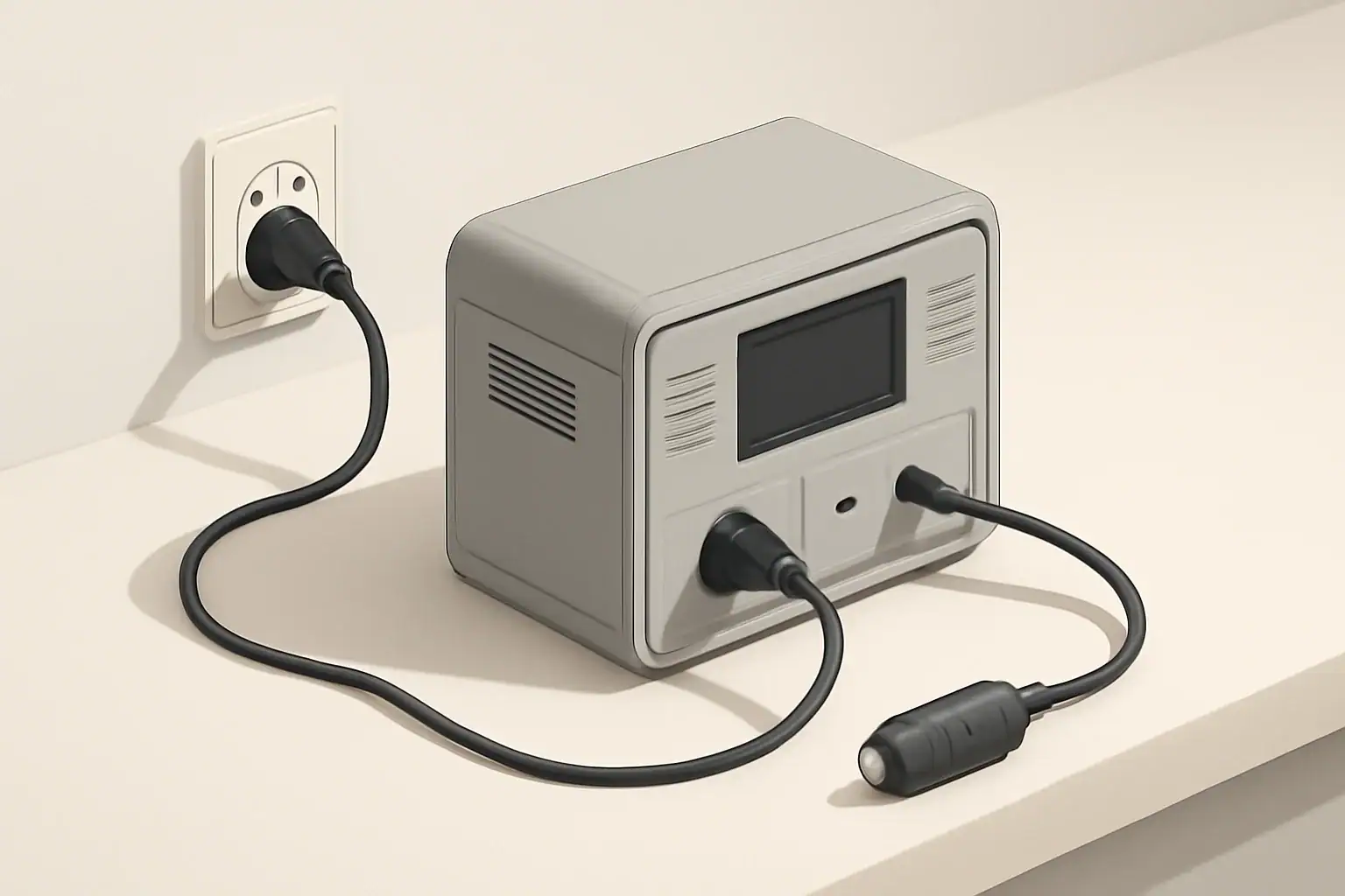
A LiFePO4 charging profile is the pattern of voltage and current a charger follows to fill a lithium iron phosphate battery safely and efficiently, usually using a constant-current then constant-voltage (CC‑CV) method. Getting this profile roughly right is what keeps your portable power station safe, charges it quickly, and helps the battery last for thousands of cycles.
If the voltage is set too high, cells can be stressed or shut down by the battery management system (BMS). If current is too high, the pack runs hot and ages faster. If both are too low, charging becomes painfully slow and you never reach the rated capacity. Understanding the LiFePO4 charge curve, recommended voltages, and current limits lets you choose chargers, solar controllers, and settings that match your battery instead of guessing.
The goal is not to hit a single “perfect” number, but to stay inside a safe window: correct CC‑CV targets, reasonable charge rate, and temperatures the BMS is happy with. The rest is about convenience, speed, and long‑term battery health.
What the LiFePO4 Charging Profile Is and Why It Matters
For LiFePO4 batteries, the charging profile describes how the charger moves through different stages as the battery fills. Almost all modern systems use a two‑stage CC‑CV profile:
- Constant current (CC): The charger pushes a fixed current into the pack until it reaches a target voltage.
- Constant voltage (CV): The charger holds that target voltage while the current naturally tapers down.
LiFePO4 cells have a nominal voltage around 3.2–3.3 V per cell and a typical full‑charge target around 3.60–3.65 V per cell. In a 4‑cell (12.8 V nominal) pack, that translates to about 14.4–14.6 V at the pack level.
This matters because LiFePO4 behaves differently from lead‑acid and other lithium chemistries:
- The usable voltage range is narrower and flatter, so small voltage changes can represent big state‑of‑charge jumps.
- LiFePO4 does not need or like long‑term “float” charging the way lead‑acid does.
- Charging at low temperatures is more restricted and must be controlled by the BMS.
When your charger respects the LiFePO4 profile, you get predictable run time, faster but safe charging, and much longer cycle life from your portable power station or standalone battery.
Key Charging Concepts and How the LiFePO4 Profile Works
To work with LiFePO4 confidently, it helps to translate the technical terms into simple ideas you can apply when setting up a charger or solar controller.
CC‑CV stages in plain English
- Constant current (bulk stage): The charger delivers a fixed current (for example, 20 A into a 100 Ah pack, or 0.2C) until the battery voltage rises to the CV setpoint (for example, 14.4 V for a 4‑cell pack).
- Constant voltage (absorption stage): Once the pack hits the CV voltage, the charger stops increasing voltage and holds it steady. The battery now decides how much current to accept. As it approaches full, the current tapers down.
- Charge termination: Charging usually stops when the tapering current falls below a small fraction of capacity (often around 0.03C–0.05C) or when a timer expires.
Unlike lead‑acid systems, LiFePO4 packs typically do not sit at a high “float” voltage for long periods. Many portable power stations simply stop charging and let the pack rest near full, then restart when the state of charge drops slightly.
Typical voltage targets by pack size
Most LiFePO4 packs used in portable power stations are made from series strings of cells. You can estimate the correct pack‑level CV voltage by multiplying the per‑cell voltage by the number of cells in series.
| Pack type | Series cell count | Nominal pack voltage | Typical CV (full charge) voltage | Approximate usable voltage range |
|---|---|---|---|---|
| 12.8 V LiFePO4 | 4S | 12.8 V | 14.4–14.6 V | 10.8–14.6 V |
| 25.6 V LiFePO4 | 8S | 25.6 V | 28.8–29.2 V | 21.6–29.2 V |
| 51.2 V LiFePO4 | 16S | 51.2 V | 57.6–58.4 V | 43.2–58.4 V |
Charging current in C‑rate terms
LiFePO4 charge current is usually expressed as a fraction of capacity, called the C‑rate:
- 0.2C: Current equals 0.2 × capacity (for a 100 Ah pack, 20 A).
- 0.5C: Current equals 0.5 × capacity (for a 100 Ah pack, 50 A).
- 1C: Current equals the full capacity (for a 100 Ah pack, 100 A).
Typical guidance for LiFePO4:
- Routine charging: 0.2C–0.5C balances speed and longevity.
- Maximum charging: Up to 1C may be allowed on some packs, but only if the manufacturer specifies it and cooling is adequate.
- Gentle charging: 0.1C–0.2C is slower but tends to reduce heat and stress.
How the BMS shapes the charging profile
The internal battery management system is the gatekeeper that enforces the safe envelope for the charging profile. It typically:
- Blocks charging if any cell exceeds its maximum voltage.
- Stops or limits charging when the pack is too cold or too hot.
- Limits charge current if the pack or wiring is overloaded.
- Performs cell balancing near the top of charge so all cells stay in step.
Even with a smart BMS, the external charger or solar controller still needs to be configured for LiFePO4 voltages and currents. The BMS is a safety net, not a replacement for correct settings.
Real‑World LiFePO4 Charging Examples
Seeing the LiFePO4 charging profile in everyday scenarios makes it easier to recognize what is “normal” and when something looks off.
Example 1: 12.8 V, 100 Ah pack on an AC charger
Imagine a 12.8 V, 100 Ah LiFePO4 battery charged from an AC wall charger rated at 20 A with a CV setpoint of 14.4 V.
- Stage 1 – CC (bulk): The charger outputs 20 A. Pack voltage rises from about 12.5 V (roughly 40–50% state of charge) to 14.4 V in around 2–3 hours.
- Stage 2 – CV (absorption): The charger holds 14.4 V. Current starts near 20 A and gradually falls. When it drops below roughly 3–5 A (about 0.03C–0.05C), the charger declares “full” and stops or switches to a very low maintenance mode.
- Result: Total time might be around 3–4 hours from 40–50% to full, depending on exact settings and temperature.
Example 2: Portable power station on solar with variable input
Now consider a portable power station with a built‑in MPPT controller, charging its internal LiFePO4 pack from solar panels.
- Morning: Sun is low, panels only provide 80 W. The MPPT controller tries to stay in CC, but the current is limited by panel output, so charging is slow.
- Midday: Panels deliver close to their rated power, say 300 W. The controller now runs a proper CC stage at the configured LiFePO4 current limit, then transitions to CV when the pack reaches its target voltage.
- Clouds and shade: Power swings up and down. The controller may bounce between CC and a partial CV stage, but the BMS still ensures the pack never exceeds safe voltage.
On days with variable sun, you might notice that the pack spends much longer in the CC‑like region and reaches full charge later than it would on a stable AC charger.
Example 3: Comparing charge times at different C‑rates
The following table shows approximate times to go from 10% to 100% state of charge for a 100 Ah LiFePO4 pack at different charge currents. The numbers are simplified but useful for planning.
| Charge current | C‑rate | Approx. time in CC stage | Approx. time in CV taper | Approx. total time (10% to 100%) |
|---|---|---|---|---|
| 10 A | 0.1C | 7–8 hours | 1–2 hours | 8–10 hours |
| 20 A | 0.2C | 3–4 hours | 1–1.5 hours | 4–5.5 hours |
| 50 A | 0.5C | 1.5–2 hours | 0.5–1 hour | 2–3 hours |
Quick rule of thumb for time estimates
You can estimate charging time with a simple formula:
- Capacity‑based: Time (hours) ≈ battery capacity (Ah) ÷ charge current (A), then add 20–30% extra for the CV taper.
- Energy‑based: Time (hours) ≈ usable capacity (Wh) ÷ input power (W), again adding time for taper and system losses.
Common LiFePO4 Charging Mistakes and Troubleshooting Cues
Most LiFePO4 problems come from incorrect charger settings, temperature issues, or misunderstandings about how “full” looks on a voltage display. Recognizing the symptoms early helps you fix configuration issues before they shorten battery life.
Frequent mistakes that distort the charging profile
- Using lead‑acid voltage presets: Lead‑acid profiles often use higher absorption voltages and long float stages. On LiFePO4, this can push cells toward overvoltage or force the BMS to cut off charging frequently.
- Assuming all lithium presets are equal: Some chargers lump multiple chemistries under a single “lithium” mode, which may not match LiFePO4’s lower per‑cell voltage.
- Oversized charge current: Setting current near or above the pack’s rated maximum leads to heat, audible fan noise, and earlier BMS current limits or thermal cutoffs.
- Interrupting the CV stage too early: Unplugging as soon as the pack hits the CV voltage (for example, 14.4 V) but before current tapers can leave 5–15% capacity unused and reduce cell balancing opportunities.
- Charging below freezing: Trying to charge at or below 32°F (0°C) without built‑in heating can trigger BMS low‑temperature lockout or cause long‑term damage if the pack allows it.
Symptoms and what they usually mean
| Symptom | Likely cause | What to check or adjust |
|---|---|---|
| Voltage never reaches expected CV value | Charger set to lower chemistry voltage or limited power | Confirm chemistry mode is LiFePO4 and verify charger wattage/current rating |
| Charger shuts off early around 80–90% SOC | BMS overvoltage or temperature protection | Reduce CV voltage slightly, lower charge current, and check pack temperature |
| Packs feels hot during fast charging | High C‑rate or poor ventilation | Lower current setting and improve airflow around the battery or power station |
| Charging disabled in cold weather | Low‑temperature charge lockout | Warm the battery above freezing before charging; avoid bypassing BMS protections |
| Runtime noticeably drops over time | Repeated partial charging or chronic imbalance | Allow occasional full CC‑CV charges so the BMS can balance cells at the top |
Simple troubleshooting sequence
- Confirm chemistry mode: Make sure the charger or controller is set to LiFePO4 or uses appropriate custom voltages.
- Measure pack voltage: Compare the measured voltage at “full” to the expected CV range for your pack size.
- Check current: Ensure the charge current is within the pack’s recommended C‑rate, especially in hot or cold conditions.
- Observe temperature: If the case is hot to the touch, reduce current and improve ventilation.
- Let the CV stage finish: Occasionally allow the charger to run until current has clearly tapered and stopped, giving the BMS time to balance.
LiFePO4 Charging Safety Basics
LiFePO4 is considered one of the safer lithium chemistries, but safe charging still depends on respecting voltage, current, and temperature limits. The charging profile is where all three come together.
Voltage and current safety margins
- Stay inside the recommended CV window: For most packs, that means around 3.60–3.65 V per cell. Going significantly higher does not add useful capacity but does add stress.
- Avoid running at maximum C‑rate constantly: Even if the datasheet allows 1C charging, using 0.5C or less for routine use leaves more margin for heat and unexpected conditions.
- Use properly sized wiring and connectors: High current in undersized cables can cause hot spots, voltage drop, and false impressions that the charger or pack is malfunctioning.
Temperature and environment
- Charging below freezing: Unless the pack has an integrated heater and is designed for it, charging below about 32°F (0°C) should be avoided to prevent lithium plating.
- High‑temperature charging: Charging in very hot environments accelerates aging and can trigger BMS thermal limits. If the enclosure feels hot, reduce charge current and improve airflow.
- Enclosed spaces: Portable power stations inside cabinets, vehicles, or tents can trap heat. Allow ventilation around vents and fans, especially during fast charging.
Relying on the BMS, but not abusing it
The BMS is designed as a safety backstop, not as a primary control method. If you frequently see the pack cutting off charging or discharging unexpectedly, treat that as a warning sign:
- Revisit charger voltage and current settings.
- Reduce power draw or charge rate in extreme temperatures.
- Investigate whether the pack is undersized for the connected loads or charging sources.
Using the BMS protections as a routine part of your charging profile (for example, relying on overvoltage cutoffs every day) will shorten battery life and may eventually lead to permanent capacity loss.
Long‑Term Care, Storage, and Profile Adjustments
Over thousands of cycles, small choices in how you charge a LiFePO4 pack add up. You can treat the charging profile as a tool for tuning both runtime and lifespan.
Everyday charging vs. maximum capacity
- For maximum cycle life: Some users intentionally charge to a slightly lower CV voltage (for example, 14.0–14.2 V for a 4‑cell pack) and accept a small reduction in usable capacity in exchange for reduced cell stress.
- For maximum runtime: Using the full recommended CV voltage and allowing a complete CC‑CV cycle provides the most energy per cycle, which is often preferred for portable power stations.
You can also combine these approaches: use a slightly reduced CV voltage for daily use and raise it to the full value occasionally to allow thorough balancing.
Storage profile and intervals
- State of charge for storage: For long‑term storage, aim for roughly 30–50% state of charge rather than leaving the pack full or empty.
- Storage temperature: Cool, dry conditions are preferred. Avoid prolonged storage in hot vehicles or unventilated sheds.
- Top‑up schedule: LiFePO4 has low self‑discharge, so checking and topping up every few months is usually sufficient. A short CC‑CV cycle back to the chosen storage level is enough.
Using the profile to keep the BMS happy over time
Because cell balancing typically happens near the top of charge, your long‑term routine should include:
- Occasional full charges that allow the CV stage to finish and current to taper.
- Monitoring whether the time spent in CV is changing significantly over months, which can hint at growing imbalance or capacity fade.
- Adjusting charge current downward if you notice the pack getting hotter or fans running more aggressively than when it was new.
Practical Takeaways and Specs to Look For
The LiFePO4 charging profile does not need to be complicated. If you keep voltage, current, and temperature in the right ballpark, the BMS takes care of the fine details and cell‑level protections.
Key practical takeaways
- LiFePO4 uses a CC‑CV charging profile with lower per‑cell voltage than many other lithium chemistries.
- For most packs, 0.2C–0.5C charge rates provide a good balance of speed and longevity.
- Charging below freezing should be avoided unless the pack is specifically designed for it.
- Finishing the CV taper periodically helps maintain capacity and allows the BMS to balance cells.
- Small adjustments to CV voltage and charge current can significantly influence long‑term cycle life.
Specs to look for when choosing chargers or power stations
When you read spec sheets or manuals, use this checklist to confirm the charging profile will work well with LiFePO4 batteries:
- Chemistry support: Explicit LiFePO4 mode or user‑programmable voltage settings.
- CV voltage range: Ability to set or confirm the correct pack‑level CV voltage (for example, around 14.4–14.6 V for 12.8 V packs).
- Charge current rating: Maximum continuous current that matches a reasonable C‑rate for your battery capacity.
- Temperature protections: Built‑in sensors and logic that prevent charging outside safe temperature limits.
- Cell balancing capability: A BMS that balances cells near full charge to keep voltages aligned over time.
- Display or indicators: Clear information on charge current, voltage, and state of charge so you can see the CC‑CV behavior in real time.
- Compatibility with solar or DC inputs: If using solar, an MPPT controller that can be configured for LiFePO4 voltages and current limits.
By matching these specs to the LiFePO4 charging profile described above, you can set up portable power systems that charge predictably, stay within safe limits, and deliver reliable performance for years.
Frequently asked questions
What charger specs and features should I check for LiFePO4 charging?
Look for explicit LiFePO4 chemistry support or user‑programmable CV voltage so you can set the correct pack‑level full voltage, and confirm the charger can limit current to an appropriate C‑rate for your battery. Also verify temperature protections and that the battery’s BMS can perform cell balancing; clear displays or indicators help you monitor CC‑CV behavior in real time.
Can I use a lead‑acid charger preset for LiFePO4 batteries?
No — lead‑acid presets typically use higher absorption and persistent float voltages that can overvoltage LiFePO4 cells or force frequent BMS cutoffs. Use a LiFePO4 mode or custom voltage settings that match the per‑cell CV target instead.
How should I charge LiFePO4 batteries in cold weather?
Avoid charging below about 0°C (32°F) unless the pack includes an integrated heater and is rated for cold charging, because low temperatures risk lithium plating. Most BMSs will block charging below their cold threshold, so warm the battery first rather than bypass safety protections.
How do I know when a LiFePO4 battery is fully charged?
A proper CC‑CV charge reaches the CV voltage and is complete when the charge current tapers to a small fraction of capacity (commonly around 0.03C–0.05C). Voltage alone can be misleading, so watch for current tapering or a charger indication that the CV stage has finished.
What is a safe routine charge rate for everyday use?
Routine charge rates of about 0.2C–0.5C balance speed and longevity for most LiFePO4 packs. While some packs permit higher rates up to 1C, only follow those limits if the manufacturer specifies them and adequate cooling is provided.
How often should I run a full CC‑CV charge to keep cells balanced?
Occasionally running a complete CC‑CV cycle to the full CV voltage helps the BMS balance cells; doing this every few months or when you notice increasing CV time or a drop in runtime is usually sufficient. Regular partial charges are acceptable, but periodic full cycles maintain long‑term state of health.
Related guides
Browse this topic →

- Beginner-friendly sizing, runtime & specs
- Solar & charging (MPPT, fast charging, cables)
- Batteries (LiFePO4, cycles, care & storage)
- Safety, cold-weather performance, real-world tips
More in Charging
See all →- Can You Daisy-Chain Portable Power Stations? Why It Usually Isn’t a Good Idea
- USB-C Input vs AC Input on Portable Power Stations: Which Charging Method Makes Sense?
- Car Alternator Charging vs Cigarette Lighter Charging: What Changes for Power Stations?
- Charging a Portable Power Station From an RV Outlet: 12V, 24V, and Safety Limits
- Fast AC Charging vs Battery Longevity: Should You Use Turbo Mode Every Time?
Keep reading
About this site
Portable Energy Lab publishes practical, independent guides about portable power—clear sizing, safe use, and real-world expectations.
Affiliate disclosure
Some links on this site may be affiliate links. If you buy through these links, we may earn a small commission at no extra cost to you. This helps support our content. Read our affiliate disclosure.