
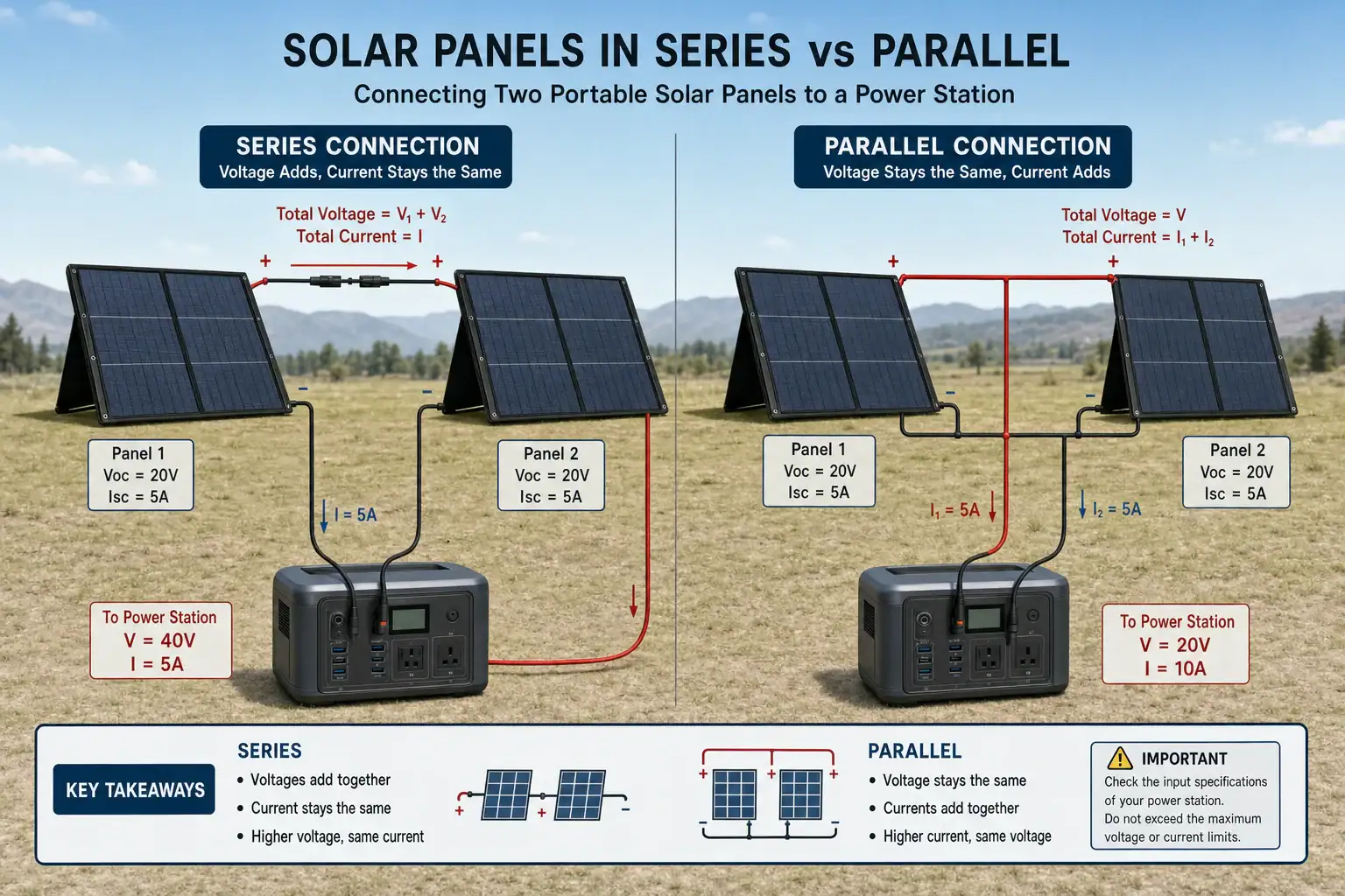
Wire solar panels in series to raise voltage, or wire them in parallel to raise current, while keeping the portable power station’s solar input limits in mind. The better configuration depends on the station’s MPPT voltage range, maximum open-circuit voltage, input current limit, solar wattage limit, and the electrical ratings of each panel.
Series wiring is often useful for reducing cable losses and reaching the minimum solar input voltage in weak sunlight. Parallel wiring can perform better when panels face different directions or experience uneven shading. Neither arrangement automatically produces more rated power: two identical panels have approximately the same combined wattage potential either way.
Before connecting an array, compare panel Voc, Vmp, Imp, and Isc ratings with the power station’s specifications. Voltage requires the most caution because exceeding the maximum solar input voltage can damage the input electronics. Current beyond the accepted limit may simply be clipped on some units, but that behavior should never be assumed without clear documentation.
1. What Series and Parallel Solar Wiring Mean
In a series connection, the positive lead of one panel connects to the negative lead of the next. The unused positive and negative leads become the array output. Panel operating voltages add together, while operating current remains approximately equal to that of one panel.
In a parallel connection, all positive leads join together and all negative leads join together through suitable branch connectors or a combiner. Voltage stays approximately equal to one panel’s voltage, while the panel currents add.
This distinction matters because a portable power station does not accept every possible voltage and current combination. Its solar charge controller normally has an operating voltage range, a maximum input voltage, a maximum current, and a wattage ceiling. The array must remain electrically compatible with all of them.
Series wiring may be preferable when the power station needs a higher startup voltage or when the panels are a long distance from the station. Higher voltage and lower current can reduce resistive loss in the cable. Parallel wiring may be preferable when one panel is likely to be shaded because shading a panel in a series string can reduce the output of the entire string.
2. How Voltage, Current, and Wattage Work
Four panel specifications are especially important. Voc is open-circuit voltage, measured when the panel is not supplying a load. Vmp is voltage near maximum power. Isc is short-circuit current, while Imp is current near maximum power.
For identical panels in series, add Voc values to estimate the array’s maximum open-circuit voltage and add Vmp values to estimate operating voltage. Do not add Imp or Isc. For identical panels in parallel, add Imp and Isc, but do not add Voc or Vmp.
Estimated power is voltage multiplied by current. Two 100-watt panels can therefore provide roughly 200 rated watts in either configuration. A series array might operate near 40 volts and 5 amps, while a parallel array might operate near 20 volts and 10 amps. Both combinations equal about 200 watts under ideal rated conditions.
Actual output is usually lower because of panel temperature, sun angle, clouds, shading, cable loss, conversion loss, and the station’s input ceiling. Cold weather also raises panel Voc. A series array that appears to fit the voltage limit at room temperature may exceed it on a clear, freezing morning, so a reasonable cold-weather voltage margin is essential.
| Two identical 100 W panels | Operating voltage | Operating current | Open-circuit voltage | Rated array power |
|---|---|---|---|---|
| Series | About 40 V | About 5 A | About 48 V | About 200 W |
| Parallel | About 20 V | About 10 A | About 24 V | About 200 W |
3. Real-World Series and Parallel Examples
Two panels and a 60 V, 12 A solar input
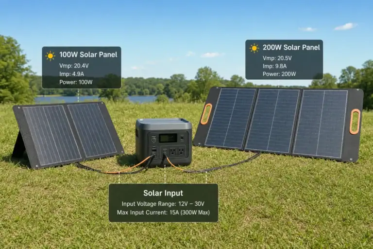
Suppose each 100-watt panel has a 20 V Vmp, 24 V Voc, and 5 A Imp. In series, the pair would have a 40 V operating voltage, 48 V rated Voc, and 5 A operating current. That configuration is within the stated voltage and current limits before accounting for the required cold-weather voltage margin.
In parallel, the same pair would operate near 20 V and 10 A, with Voc remaining near 24 V. This also fits the example input. The practical choice could depend on shading, cable length, connector availability, and the minimum MPPT operating voltage.
Four panels on a current-limited input
Four of those panels connected only in parallel would produce roughly 20 V and 20 A. If the station accepts no more than 12 A, a substantial portion of the array’s potential current may be unavailable. Whether the controller safely clips extra current must be confirmed in its documentation.
A two-series, two-parallel configuration, commonly described as 2S2P, would operate near 40 V and 10 A. Its rated Voc would be about 48 V. This arrangement can deliver the four panels’ combined potential within the example current limit, provided the cold-adjusted Voc remains safely below the station’s maximum voltage.
Uneven shade across two panels
If two panels are in series and one is heavily shaded, string current can fall because the same current flows through both panels. Bypass diodes may reduce the effect, but performance still depends on panel design and shading pattern. In parallel, the unshaded panel can generally continue contributing its own current more independently, although the shaded panel’s output will still decline.
4. Common Wiring Mistakes and Troubleshooting Cues
Exceeding maximum input voltage
This is the most serious calculation error. Add panel Voc ratings for every panel in a series string, then adjust for the expected lowest temperature. Do not use Vmp alone to check the maximum voltage. If the calculated cold Voc approaches or exceeds the station’s limit, use fewer panels per string.
Confusing current limits with wattage limits
An array may be below the wattage limit but above the current limit, or below the current limit but above the voltage limit. Check each value separately. If input power plateaus below the panels’ rating in strong sun, the station may be clipping current or wattage rather than malfunctioning.
Mixing mismatched panels
In series, the lowest-current panel tends to constrain string current. In parallel, panels with substantially different operating voltages may not share power effectively. For predictable performance, use panels with closely matched Vmp, Voc, Imp, and cell characteristics.
Reversed polarity or an incompatible adapter
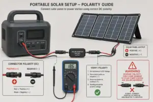
Connectors that physically fit do not always share the same polarity or pin arrangement. If the station reports no solar input, inspect polarity markings, adapter specifications, and fully seated connections before assuming a panel has failed. Never repeatedly test a questionable adapter by trial and error.
Output changes during the day
Low input can result from clouds, heat, poor panel angle, partial shade, dirty surfaces, or the battery nearing full charge. Test under direct midday sun with the battery at a moderate state of charge. Compare conditions before changing the wiring layout.
5. Solar Wiring Safety Basics
Keep total series Voc below the station’s maximum solar input voltage under the coldest realistic conditions. Unlike excess wattage that may be electronically limited, excess voltage can damage components. Leave margin rather than designing directly at the published ceiling.
Use cables, branch connectors, and adapters rated for the array’s voltage, current, temperature, and outdoor exposure. Parallel wiring increases current, so undersized cable can create voltage drop and unwanted heating. Connectors should be dry, clean, fully engaged, and protected from strain.
Solar panels generate electricity whenever illuminated. Cover or turn panels away from direct sunlight before making or separating connections when practical. Avoid disconnecting energized connectors under substantial load because direct current can sustain an arc. Connect the array according to the power station manufacturer’s stated connection sequence.
Do not use improvised bare-wire joints, altered connectors, or adapters with unknown polarity. Stop using any cable that is hot, discolored, cracked, loose, or corroded. Keep the power station dry and within its specified operating temperature range.
Larger arrays may require overcurrent protection, disconnect equipment, grounding measures, or other system-specific safeguards. Requirements depend on array design and local electrical rules. Consult a qualified electrician for fixed installations, unusually large portable arrays, or any connection involving building wiring. Do not connect a portable solar array directly to a home electrical panel.
6. Maintaining and Storing a Portable Solar Array
Inspect connectors and cables before each extended trip or seasonal use. Look for bent contacts, looseness, damaged insulation, corrosion, or dirt that could increase resistance. Wipe connector exteriors with a dry cloth and keep protective caps installed during storage. Do not insert tools or cleaning fluids into energized contacts.
Keep panel surfaces reasonably clean using the panel maker’s recommended method. Dust, pollen, bird droppings, and leaves can reduce output, and concentrated shade across a row of cells may affect a series string more than expected. Avoid abrasive cleaners that could damage surface coatings.
Label series strings, parallel branches, adapters, and extension cables so the intended layout is easy to recreate. Record each panel’s electrical ratings and the calculated array Voc, Vmp, Imp, and Isc. Recheck the calculations whenever a panel is added or replaced.
Store foldable or portable panels dry, supported, and protected from sharp bends or heavy objects. Coil cables loosely rather than folding them tightly near connector ends. Before storage, disconnect the array from the power station and follow the station’s separate battery storage guidance.
| Symptom | Possible wiring-related cause | Useful check |
|---|---|---|
| No solar input | Reversed polarity, loose adapter, or voltage below startup range | Verify markings, connections, and array voltage specifications |
| Power plateaus in full sun | Current or wattage input clipping | Compare array Imp and watts with station limits |
| Large loss from one shaded panel | Series string current is being constrained | Remove shade or compare with a compatible parallel layout |
| Connector or cable feels hot | Loose contact, corrosion, or undersized cable | Disconnect safely and replace damaged or unsuitable parts |
Related guides: How to Read Solar Panel Specs for Power Stations: Voc, Vmp, Imp, and Why It Matters • Overpaneling Explained: Can You Connect Bigger Solar Panels Than the Input Limit? • Solar Extension Cables and Voltage Drop: When Cable Length Starts to Matter • Solar Safety Basics: Cables, Heat, and Preventing Connector Melt
7. Practical Takeaways and Specs to Look For
Choose series wiring when higher voltage is needed to enter the MPPT range, cable runs are longer, or the station has a relatively low current limit. Choose parallel wiring when panel-level shading varies, lower array voltage is desirable, and the input and cables can handle the combined current. A series-parallel arrangement can balance both requirements for larger arrays.
Always calculate series voltage from Voc and parallel current from Isc as well as normal operating values. Confirm connector polarity, use closely matched panels, and allow cold-weather voltage headroom. The safe configuration is the one that satisfies every input limit, not merely the advertised wattage limit.
Specs to look for
- Maximum solar input voltage: Look for a clearly stated limit such as 50 V, 60 V, or 150 V; it determines how many panel Voc ratings can be added in series without exceeding the input.
- MPPT operating voltage range: Look for a range such as 15–50 V or 30–120 V; the array’s normal Vmp should fall inside it for reliable charging.
- Solar startup voltage: Look for a stated minimum, often around 10–30 V; a single low-voltage panel may not start charging if it falls below this threshold.
- Maximum input current: Look for values such as 10 A, 15 A, or 20 A; this controls how much parallel panel current the station can use.
- Maximum solar input wattage: Look for an input rating appropriate to the planned array, such as 200–1,000 W; excess rated panel capacity may be clipped during strong sun.
- Accepted connector and polarity: Look for an explicitly documented connector type, pin arrangement, and polarity; physical compatibility alone does not guarantee a safe connection.
- Cold-temperature voltage margin: Look for enough space between calculated cold Voc and the input ceiling, often at least 10–20 percent depending on climate and panel coefficient; this helps prevent overvoltage on cold mornings.
- Cable current rating and wire size: Look for cable sized above expected continuous current, such as 10–15 A for smaller arrays or more for parallel systems; adequate size reduces heat and voltage drop.
- Overvoltage, overcurrent, and overtemperature protection: Look for clearly documented input protections; they add fault protection but do not make an incompatible array safe.
A final compatibility check should compare the complete array, not just one panel, with the portable power station. Include the number of panels per series string, the number of parallel strings, expected temperatures, cable length, and likely shading conditions before connecting the system.
Frequently asked questions
Is series or parallel better for charging a portable power station?
Neither configuration is always better. Series is often useful when the station needs higher input voltage or the cable run is longer, while parallel can be useful when panels receive uneven sun or shade. The correct choice must stay within the station’s voltage, current, and power limits.
What solar panel specs should I check before connecting panels to a portable power station?
Check each panel’s Voc, Vmp, Isc, and Imp, then calculate the values for the complete array. Compare them with the power station’s maximum solar input voltage, MPPT operating range, startup voltage, maximum input current, maximum input wattage, and documented connector polarity. Cold-weather Voc margin is particularly important for series strings.
Can I connect solar panels with different wattages in series or parallel?
It is usually best to use closely matched panels. In series, the lower-current panel can limit the string, while in parallel, panels with meaningfully different operating voltages may share power poorly. Different panel wattages may work in some cases, but their electrical ratings should be evaluated rather than relying on wattage alone.
What is the most common mistake when wiring solar panels to a power station?
A common mistake is checking only panel wattage and overlooking array voltage. The Voc values of panels in a series string add together and can exceed the station’s maximum input voltage, especially in cold weather. Also verify current limits, connector polarity, and the required MPPT or startup voltage.
Will solar panels in parallel charge better in partial shade?
Parallel wiring can allow an unshaded panel to continue contributing current more independently when another panel is shaded. In a series string, substantial shading on one panel can reduce current through the whole string. Actual results still vary with panel design, bypass diodes, shading pattern, and the power station’s controller.
Is it safe to connect more solar panel wattage than a portable power station is rated for?
Only connect an oversized array if the station documentation permits it and every voltage and current limit remains within specification. Some controllers limit or clip excess available wattage, but that does not protect against excessive voltage or necessarily excessive current. Use correctly rated cables and connectors, avoid unknown adapters, and do not make or break loaded connections unnecessarily.
Recommended next:
- Are Portable Power Stations the Future of Backup Power?
- Portable Power Stations and Renewable Energy
- Solar Panel Series vs Parallel: Which Is Better for Charging a Power Station?
- How Many Solar Watts Do You Need to Fully Recharge in One Day?
- Overpaneling Explained: Can You Connect Bigger Solar Panels Than the Input Limit?
- Shading and Angle: How Placement Changes Solar Charging Speed
- More in Solar →
Related guides
Browse this topic →
- Beginner-friendly sizing, runtime & specs
- Solar & charging (MPPT, fast charging, cables)
- Batteries (LiFePO4, cycles, care & storage)
- Safety, cold-weather performance, real-world tips
More in Solar
See all →- Can You Charge a Portable Power Station Through a Window With Solar Panels?
- Best Solar Panel Angle for a Portable Power Station: Faster Charging Without Guesswork
- Solar Charging in Partial Shade: Why One Shadow Can Slow the Whole Setup
- Bifacial Solar Panels and Portable Power Stations: When the Extra Output Helps
- Can You Mix Solar Panels With Different Wattages on a Portable Power Station?
Keep reading
About this site
Portable Energy Lab publishes practical, independent guides about portable power—clear sizing, safe use, and real-world expectations.
Affiliate disclosure
Some links on this site may be affiliate links. If you buy through these links, we may earn a small commission at no extra cost to you. This helps support our content. Learn more.