MC4, Anderson, DC Barrel: Solar Connectors and Adapters Explained

Portable power station connected to solar panel with various connectors

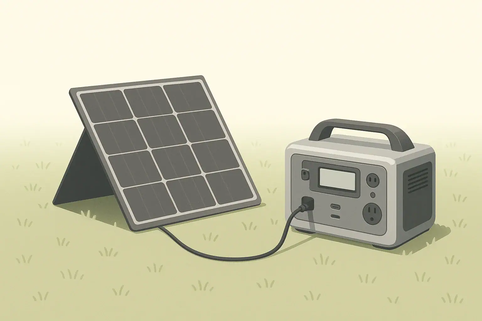
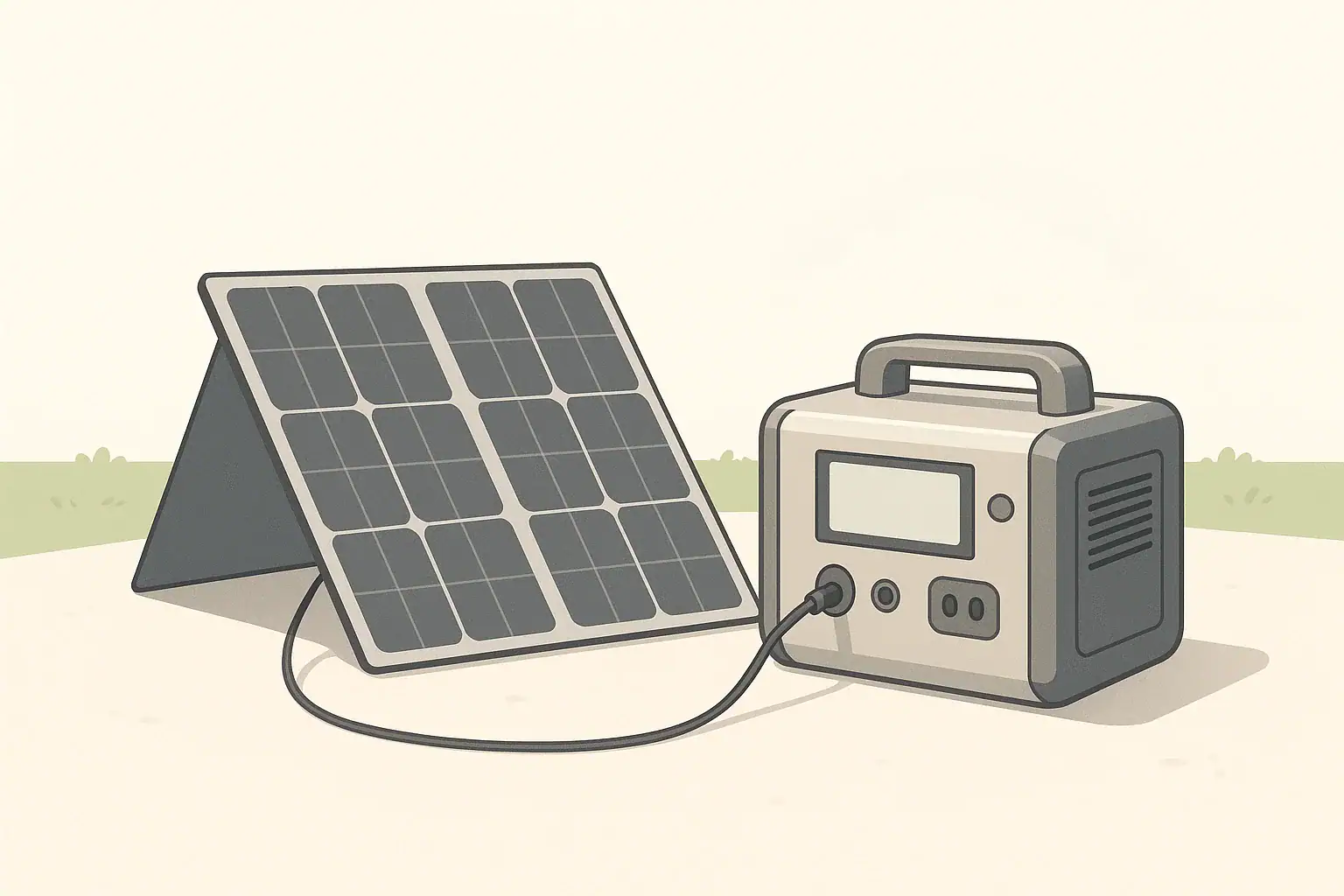
Why Solar Connectors Matter for Portable Power Stations

Portable power stations make it easy to use solar panels for camping, RVs, remote work, and short power outages. But solar panels and power stations do not always share the same plugs. Understanding common connector types and how to use adapters helps you charge safely and get the most from your solar setup.

This guide explains the most common low-voltage solar connectors you will see with portable power stations in the U.S.: MC4, Anderson-style, DC barrel plugs, and a few others. It focuses on how they relate to real-world use cases, not brand-specific systems.

We will cover:

  • What MC4, Anderson, and DC barrel connectors are and where they are used
  • How to choose compatible panels, cables, and adapters
  • Basic safety limits and good practices for low-voltage solar wiring
  • How connectors affect charging speed and system planning

Overview of Common Solar Connector Types

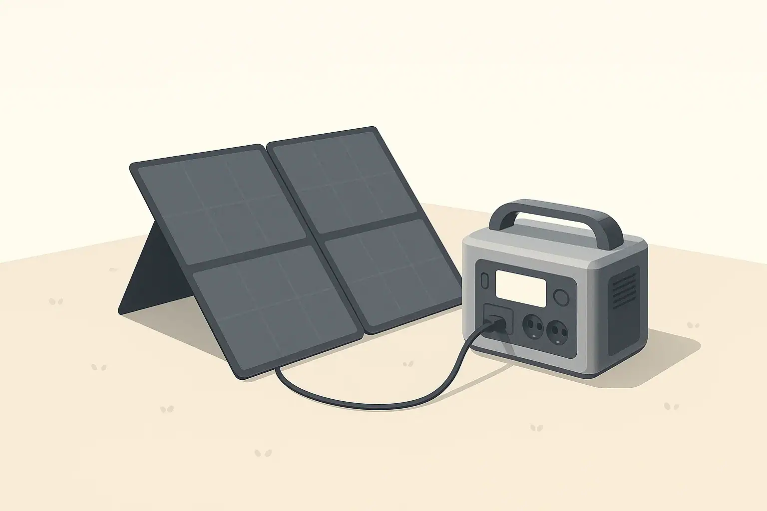
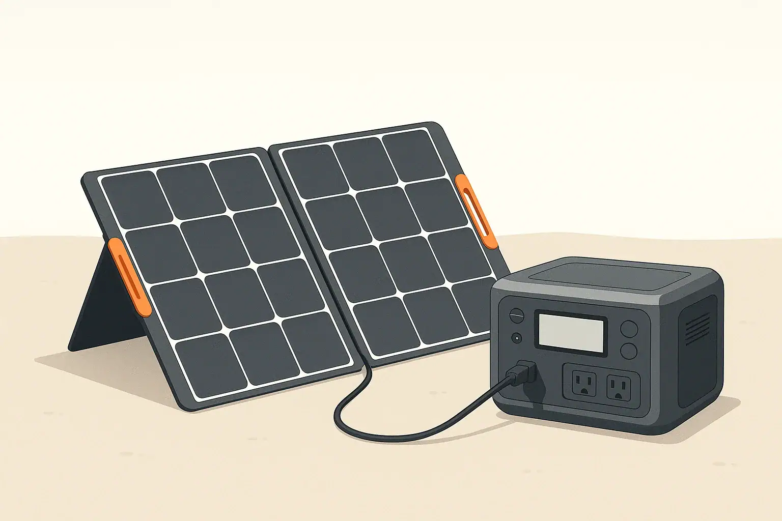
Most portable power station solar setups use 12–48 V DC. At these voltages, different connectors are chosen for convenience, current capacity, and weather resistance. Below are the main connector families you will encounter.

MC4 Connectors

MC4 is the de facto standard connector for many rigid and foldable solar panels. MC4 connectors are:

  • Weather-resistant: Designed for outdoor use on solar panels.
  • Locking: They click together so they do not separate accidentally.
  • Polarized: One side is positive and the other negative, helping prevent reverse polarity connections.

Panels with MC4 leads usually connect to a portable power station using an adapter cable, such as MC4 to DC barrel or MC4 to Anderson-style, depending on the power station’s input port.

Anderson-Style Connectors

Anderson-style connectors (often two flat contacts in a colored housing) are common in DC power systems and some higher-current solar connections. For portable power station use, they are typically:

  • High-current capable: Suitable for higher wattage inputs where a small barrel connector might be undersized.
  • Genderless: Many Anderson housings are mated with identical pieces, simplifying connections.
  • Used for modular setups: You may see them between panels, extension cables, or between a combiner and the power station.

Portable power stations that accept Anderson-style inputs often provide a dedicated high-current solar input. Panels may then connect via MC4-to-Anderson or other adapter cables.

DC Barrel Connectors

DC barrel connectors are the round plug-and-sleeve style jacks commonly found on laptop chargers and many portable power stations. Their key traits are:

  • Compact size: Convenient for smaller systems and lower solar input power.
  • Many sizes: Different inner and outer diameters require the correct matching plug.
  • Polarity and voltage sensitive: The center pin is usually positive, but you must confirm with the device documentation.

Solar panels do not usually come with DC barrel plugs directly attached. Instead, an adapter converts from MC4 or another connector type to the barrel size your power station uses.

Other Low-Voltage Solar Connectors You May See

Beyond MC4, Anderson-style, and DC barrel plugs, you may encounter:

  • 8 mm or proprietary round ports: Functionally similar to DC barrel but with a brand-specific size or pin layout.
  • Automotive 12 V sockets: Panels or charge cables terminating in a plug for an automotive-style 12 V outlet on a power station.
  • Terminal blocks or ring terminals: Used on some charge controllers and distribution panels, less common directly on portable power stations.

In most portable use cases, you will be converting from panel MC4 leads into whatever input style your power station accepts.

Checklist for Selecting Solar Connectors and Adapters

Example values for illustration.

What to check Why it matters Notes
Connector type on solar panel (e.g., MC4) Determines which adapter cable you need Match panel leads to power station input style
Connector type on power station (barrel, Anderson-style) Prevents incompatible or loose connections Confirm size and polarity in the manual
Maximum input voltage rating of power station Avoids over-voltage damage to electronics Example: 12–30 V DC or similar range
Maximum input current / watts Ensures connectors and cables are sized correctly Choose wiring that comfortably exceeds expected current
Cable length and gauge Long or thin cables cause voltage drop and heat Shorter, thicker cables generally perform better
Weather exposure Outdoor connectors should resist moisture and UV MC4-style is common for outdoor panel leads
Locking or strain relief features Reduces accidental unplugging or wire damage Useful in wind, RV, or mobile setups

MC4 Connectors in Detail

Because so many solar panels use MC4 leads, understanding their behavior helps you design safer, more reliable setups.

Polarity and Panel Leads

Each panel typically has two MC4 leads:

  • One for positive (+)
  • One for negative (−)

The connectors are keyed so the positive only mates with the correct counterpart and the negative with its own counterpart. Despite this, you should still verify polarity on adapter cables, particularly if they were assembled by hand.

Series and Parallel Panel Connections

MC4 connectors allow simple series or parallel wiring between compatible panels. However, when working with portable power stations, do not exceed the station’s rated solar input voltage or current.

  • Series (voltage adds): Two panels in series roughly double the voltage while current stays similar.
  • Parallel (current adds): Two panels in parallel keep the voltage similar while current roughly doubles.

Before combining panels, check the maximum DC input voltage and current limit of your power station. Stay under both limits with some safety margin, and follow the panel and device documentation. If you are unsure how to calculate combined voltage and current safely, seek advice from a qualified solar professional.

Extending MC4 Cables

Extension cables with MC4 ends are widely available. When extending runs between panels and your power station:

  • Keep cable runs as short as practical to reduce voltage drop.
  • Use appropriate wire gauge for the expected current and length.
  • Route cables to avoid trip hazards, sharp edges, and pinching points.

Because MC4 connections are often outdoors, ensure each connection is fully seated and latched to minimize moisture ingress.

Anderson-Style Connectors in Portable Solar Setups

Anderson-style connectors are popular in hobbyist, RV, and off-grid systems, and occasionally appear on portable power stations as a higher-current DC input or output.

Why Anderson-Style Is Common for Higher Power

Compared to many barrel connectors, Anderson-style connectors:

  • Offer more robust contact area for higher currents.
  • Can be easier to connect and disconnect while wearing gloves.
  • Are often used for modular components such as extension leads, distribution blocks, and portable solar combiner boxes.

These traits make them useful when your solar array feeds more than a small trickle charge, such as when using multiple portable panels or operating in an RV where higher power is common.

Using Anderson Inputs on Power Stations

If your power station provides an Anderson-style solar input, it usually operates in the same voltage range as its other DC solar ports. The difference is the connector’s physical capacity and ease of connection.

Typical use cases include:

  • Connecting a combiner that joins several MC4-equipped panels.
  • Using a single, heavier cable run from panels to the power station to minimize voltage drop.
  • Connecting to auxiliary batteries or DC distribution (where supported and documented by the manufacturer).

Always follow the power station’s manual regarding which connectors can be used simultaneously and the total allowable solar input. Do not assume you can exceed the published solar input rating by using more than one connector at once.

DC Barrel and Other Round Power Connectors

Many compact portable power stations use DC barrel or proprietary round ports for solar and car charging. These connectors are familiar from other consumer electronics but must be treated carefully in solar applications.

Matching Size and Polarity

DC barrel connectors vary by:

  • Outer diameter (for the jack body)
  • Inner diameter (for the center pin)
  • Length and pin depth

Using the wrong size can result in:

  • Loose connections that overheat or disconnect easily.
  • Plugs that do not fully insert, reducing contact area.

Polarity is just as important. The majority of DC barrel ports use center-positive wiring, but you must confirm with the device documentation. An incorrect polarity adapter can immediately damage electronics.

Current Limits and Heating

DC barrel connectors are practical for moderate solar input currents. Pushing them near or beyond their design limit can cause:

  • Excessive heating of the plug or jack.
  • Intermittent charging as thermal expansion loosens the connection.
  • Long-term wear or damage to the port.

To avoid these problems, keep solar input within the power station’s rating and avoid using undersized, thin adapters or long, light-gauge cables.

Choosing and Using Solar Adapter Cables

Because panels and power stations rarely share the same connector type, adapter cables are a key part of most setups. Thoughtful selection improves both safety and convenience.

Common Adapter Paths

Some typical adapter paths for portable power stations include:

  • MC4 (panel) → DC barrel (power station)
  • MC4 (panel) → Anderson-style (combiner or power station)
  • MC4 (panel) → proprietary round solar input

Adapters may be single-piece cables or assembled from individual connectors and extension leads. Fewer connection points usually mean fewer potential failure points.

Verifying Compatibility

Before using an adapter cable, check:

  • Voltage range: Panel open-circuit voltage must stay within the power station’s DC input range.
  • Polarity: Use markings or a multimeter (if you are qualified and comfortable doing so) to confirm the adapter delivers the correct polarity at the power station plug.
  • Connector fit: The plug should insert fully and snugly with no wobble.
  • Cable quality: Look for flexible insulation and adequate wire thickness for the current.

When in doubt, seek guidance from documentation or a knowledgeable technician instead of guessing at connector type or pinout.

Avoiding Daisy Chains of Adapters

It is tempting to string multiple adapters together (for example, MC4 to Anderson, Anderson to barrel, barrel to proprietary plug). This can introduce:

  • Extra resistance and voltage drop.
  • More failure points.
  • Greater chance of mixing up polarity or shorting connectors.

Whenever possible, use a single, purpose-built adapter cable or reduce the number of separate adapters between your panel and power station.

Safety Considerations with Solar Connectors

Even though portable solar systems operate at lower voltages than home wiring, they can still produce significant current and energy. Careful handling of connectors and adapters helps prevent damage and reduces risk of fire or injury.

Basic Low-Voltage Solar Safety

General precautions include:

  • Do not short the panel leads together; this can create sparks and heat.
  • Cover panel faces or disconnect them when connecting or reconfiguring wiring.
  • Keep connectors dry and free of debris; moisture can cause corrosion or arcing.
  • Do not modify internal wiring of power stations, panels, or charge controllers.
  • Use cables and connectors rated for the expected current and environment.

Cable Routing and Strain Relief

Poor cable management can cause invisible damage that shows up later as overheating or intermittent charging. To reduce this risk:

  • Avoid tight bends near the connector; use gentle curves.
  • Keep cables off sharp edges and away from pinch points such as doors.
  • Use strain relief or simple cable ties to prevent tension on connectors.
  • Route cables where they will not be tripped over or run over by vehicles.

Working Around RVs, Vehicles, and Buildings

Portable power stations are often used alongside RVs or as temporary backup near a home. Keep these points in mind:

  • Do not attempt to wire a portable power station directly into a home electrical panel, generator inlet, or transfer switch unless a qualified electrician designs and installs the system.
  • Avoid routing low-voltage solar wiring where it could be confused with or tied into mains-voltage wiring.
  • Clearly separate and label DC solar circuits in more permanent RV or off-grid builds.

Connectors, Charging Speed, and System Planning

The connector itself does not increase or decrease power production, but it influences what cable sizes you can use and how easily you can scale your system. That, in turn, affects charging time and practical use during outages or trips.

Solar Input Limits of Portable Power Stations

Each power station has a maximum solar input power, often expressed in watts, along with a voltage and current range. For example, a unit might accept up to a few hundred watts between a certain voltage range. Staying within these limits is essential regardless of connector type.

Connectors matter when you approach these limits:

  • For lower solar input (for example, under roughly 150–200 W), DC barrel connectors are often adequate when properly sized.
  • For higher input, Anderson-style or specialized high-current connectors may be more suitable.
  • MC4 on the panel side remains useful across a wide range of system sizes.

Estimating Charging Time from Solar

To estimate charging time from solar, you can use a simplified approach:

  • Battery capacity in watt-hours (Wh) ÷ effective solar charging power in watts (W) ≈ hours of ideal charging.

Real-world conditions (clouds, angle, temperature, and losses in wiring and electronics) often reduce effective power. Planning with a conservative assumption—such as 50–70% of panel nameplate rating over several sun hours—provides more realistic expectations.

Connectors and wiring affect these losses. For instance, long, thin cables with undersized connectors can cause noticeable voltage drop and heat, reducing the power delivered to the power station.

Use Cases and Connector Choices

Different scenarios favor different connector strategies:

  • Camping and short trips: One foldable MC4-equipped panel with a single MC4-to-barrel or MC4-to-Anderson adapter is usually sufficient.
  • RV and vanlife: Anderson-style connectors and MC4 extensions can simplify plugging and unplugging roof or portable panels.
  • Home emergency backup: A small ground-deployed array with MC4 leads, feeding the power station via a robust adapter, can be set up in a safe outdoor spot and run extension cords indoors for critical loads.

In all cases, keep the power station itself in a dry, well-ventilated area and avoid covering it with blankets, clothing, or other items while charging or discharging.

Solar Sizing Quick-Plan with Connector Considerations

Example values for illustration.

Panel watts range (nameplate) Sun hours example per day Energy per day example (Wh) Connector and cabling notes
60–80 W 4–5 h ~240–400 Wh MC4 panel leads to DC barrel often sufficient for small power stations
100–150 W 4–5 h ~400–750 Wh Use short, adequately thick cables to limit voltage drop
200–300 W 4–5 h ~800–1500 Wh Anderson-style inputs or larger barrel ports may be preferable
300–400 W 4–5 h ~1200–2000 Wh Plan for heavier-gauge extension cables and secure connectors
400–600 W 4–5 h ~1600–3000 Wh Check power station max solar input; may need multiple inputs or controller
600–800 W 4–5 h ~2400–4000 Wh More common in RV or semi-permanent systems; professional guidance helpful

Practical Tips for Reliable Solar Connections

Once you understand MC4, Anderson-style, and DC barrel connectors, a few habits go a long way toward trouble-free operation.

  • Label your cables: Simple tags or color coding for panel, extension, and adapter cables reduce confusion when setting up in a hurry.
  • Test new adapters in daylight: Verify polarity and fit before relying on a setup during a storm or overnight trip.
  • Keep spares: A spare adapter cable or MC4 extension can save a trip if one becomes damaged.
  • Inspect periodically: Look for discoloration, melted plastic, or loose housings; retire suspect parts.
  • Store dry and coiled: Avoid tight knots and bending cables sharply when packing them away.

With the right connectors and adapters, your portable power station and solar panels can work together efficiently across many scenarios—from weekend camping to short home outages—without complicated wiring or permanent installation.

Frequently asked questions

Can I connect multiple MC4 solar panels in series to charge a portable power station?

Yes — panels can be connected in series to raise voltage, but only if the combined open-circuit voltage stays below the power station’s maximum DC input rating. Series wiring increases voltage while current remains the same, so verify the station’s voltage range and allow a safety margin for cold-weather higher Voc.

Is it safe to use an MC4-to-DC-barrel adapter with high-wattage panels?

It can be safe if the adapter, the barrel connector, and the wiring are all rated for the panel’s current and power and the power station accepts that input. DC barrel ports are often suitable for moderate currents; for higher-wattage arrays prefer larger connectors or heavier-gauge cabling and confirm the power station’s maximum solar input.

How do I verify polarity when using adapter cables between panels and a power station?

Check cable markings and the device manual, then use a multimeter to confirm which conductor is positive and which is negative at the plug before making the connection. Never assume center-positive or center-negative—always verify for each setup to avoid damaging equipment.

What cable gauge should I use for solar runs to minimize voltage drop?

Use thicker conductors for longer runs and higher currents to keep voltage drop low; a common goal is under about 3% drop. Short, low-current setups can use lighter gauge wire, while runs carrying tens of amps typically need 12–10 AWG or thicker depending on length — consult a voltage-drop chart or an electrician for exact sizing.

Can I safely combine multiple adapter types (MC4 → Anderson → barrel) in one solar run?

While possible, chaining several adapters is generally discouraged because each extra connection adds resistance, more potential failure points, and a higher chance of wiring mistakes. Whenever practical, use a single purpose-built adapter or minimize the number of adapters between the panel and power station for a more reliable, lower-loss connection.

Shading and Angle: How Placement Changes Solar Charging Speed

portable power station connected to solar panel outdoors

Why Placement Matters for Solar Charging Speed

Solar panels for portable power stations are very sensitive to placement. Two identical panels in the same area can deliver very different charging speeds depending on shading, angle, direction, and temperature. Understanding these factors helps you get closer to the panel’s rated output in real conditions and plan realistic charging times for camping, RV use, or backup power.

Most portable setups use small to medium solar panels, so every watt counts. When the sun is low, partially blocked, or hitting the panel at a steep angle, the charging power can drop sharply. With a few simple placement habits, you can often double or even triple the energy you collect over a day compared with a poorly positioned panel.

How Shading Affects Portable Solar Panels

Shading is one of the biggest factors that reduce solar charging speed. Even small shadows can have an outsized impact on output, especially on compact folding panels commonly used with portable power stations.

Partial Shade Versus Full Sun

Solar cells in a panel are wired together in series and parallel strings. When part of a string is shaded, that section can limit current for the entire string. Many panels have bypass diodes to reduce losses, but shading can still cut power significantly.

In practical terms, this means:

  • A palm-sized shadow from a branch or pole can drop output well below half of full-sun power.
  • Uneven shade moving across the panel (from trees or buildings) can cause power to fluctuate from minute to minute.
  • Consistent full sun for fewer hours is usually better than partial shade over a longer period.

Common Real-World Shading Sources

When you set up a panel, look for these common sources of shade:

  • Trees and branches that cast narrow, moving shadows.
  • RV roofs and roof racks that shade certain angles during parts of the day.
  • Nearby tents, coolers, and gear that block low-angle morning or evening sun.
  • Balcony railings and fences that create banded shadows as the sun moves.
  • Self-shading from panels leaning against objects, where the object blocks part of the panel.

How to Spot and Avoid Hidden Shade

Shade often moves quickly. A spot that looks sunny when you set up may be shaded 30 minutes later. To reduce shading losses:

  • Watch the ground shadows for a minute or two to see where they are moving.
  • Check the panel surface from a short distance away; look for narrow or patchy shadows.
  • Re-check every hour or so, especially near trees or tall objects.
  • If possible, place the panel in open ground away from trunks, masts, or railings.
Shading and Angle Checklist Before Solar Setup

Example values for illustration.

Quick checks to improve portable solar charging performance
What to check Why it matters Quick notes
Overhead and side shade sources Shadows can cut power far more than expected. Walk around and look for trees, poles, railings.
Ground shadows over next 1–2 hours Sun movement may shade the panel soon. Note where shadows are moving, not just where they are.
Panel tilt and direction Aligning with the sun increases output. Face toward the sun and tilt roughly toward it.
Panel cleanliness Dirt and dust scatter light and reduce power. Wipe gently with a soft, non-abrasive cloth.
Panel temperature Very hot panels can lose efficiency. Allow airflow behind panel; avoid laying flat on very hot surfaces.
Cable routing Loose or damaged cables can waste energy. Use undamaged cables, avoid sharp bends and trip hazards.
Connection to power station Secure connections prevent intermittent charging. Ensure plugs are fully seated and ports match panel output specs.

Panel Angle, Direction, and the Path of the Sun

Even in full sun, the angle between the panel and the sun’s rays strongly affects charging speed. A panel produces the most power when sunlight hits it close to perpendicular (straight on). When the sun is far off to the side, the same panel area collects much less energy.

Facing the Right Direction (Azimuth)

In the United States, the sun is generally to the south at midday. For most locations and portable uses:

  • Point panels roughly toward the south for best all-day performance.
  • If you only charge in the morning, slightly southeast can favor earlier sun.
  • If you mainly charge in the afternoon, slightly southwest can help.

Exact compass direction is less critical for short trips than avoiding shade and getting a reasonable tilt, but large misalignment (for example, pointing east when you need afternoon power) will reduce energy collection.

Choosing a Tilt Angle Without Complicated Math

Fixed solar installations often use precise angles based on latitude. Portable users usually need simple, flexible rules of thumb. For a typical trip in the continental U.S., rough guidelines include:

  • Summer: A shallower tilt (panel closer to flat) works well because the sun is higher in the sky.
  • Winter: A steeper tilt (panel more upright) helps catch the lower sun.
  • All-purpose: Set the panel so it roughly faces the sun at the time of day when you expect the most charging.

If you do not want to adjust frequently, a simple approach is to lean the panel at about a medium angle and make sure it sees clear sky to the south for most of the day.

Adjusting During the Day Versus Set-and-Forget

Tilting the panel a few times a day to follow the sun can increase energy yield compared with a fixed angle. However, frequent adjustment is not always practical, especially if you leave the campsite or work remotely.

To balance effort and benefit:

  • Prioritize aligning the panel well for the strongest sun hours (typically late morning to mid-afternoon).
  • If possible, do two or three quick adjustments during the day—morning, midday, and afternoon.
  • If you must “set and forget,” choose an angle that favors the time when your battery is lowest and you most need fast charging.

Other Real-World Factors That Change Solar Charging Speed

Shading and angle are the main placement issues, but several other conditions influence how fast your portable power station charges from solar.

Weather, Clouds, and Haze

Solar panels respond to light intensity, not just whether it feels bright out. Weather can change output significantly:

  • Clear sky, direct sun: Often gives output near the realistic maximum for your panel.
  • Light haze or thin clouds: May reduce power noticeably but can still provide useful charging.
  • Heavy overcast: Output may drop to a small fraction of clear-sky power.

Even on cloudy days, maintaining good angle and avoiding shading helps you capture as much as possible from the available light.

Panel Temperature and Airflow

Solar panels can become very warm in direct sun, especially when placed flat against a dark surface. High temperatures tend to reduce panel efficiency.

For portable setups:

  • Avoid placing panels directly on very hot surfaces such as dark roofs or asphalt when possible.
  • Allow some airflow behind the panel by tilting or propping it up.
  • Do not cover panels with plastic or fabric while operating; this can trap heat and reduce output.

Panel Cleanliness and Surface Condition

Dust, pollen, bird droppings, and fingerprints can scatter light and reduce power output. The effect is larger on small panels because each cell contributes a bigger share of the total.

Basic care tips:

  • Wipe the panel gently with a clean, soft, non-abrasive cloth when it looks dusty.
  • Avoid harsh scrubbing or strong chemicals that could damage the surface.
  • Do not stand or place heavy objects on the panel; this can cause micro-cracks that are not visible but reduce performance.

Cables, Connectors, and Power Station Limitations

Even if the panel itself is well placed, the rest of the system can limit charging speed:

  • Cable length: Very long, thin cables can cause voltage drop and reduce charging efficiency.
  • Connector fit: Loose or partially seated plugs can cause intermittent charging or higher resistance.
  • Power station input rating: The power station can only accept solar input up to its rated limit, regardless of how strong the sun is.

Check that your panel’s voltage and connector type are compatible with your portable power station, and use cables in good condition that are suited to the current they carry.

Planning Solar Charging Time for Realistic Use

Because placement conditions change so much, real-world solar charging speeds are almost always lower than the panel’s advertised wattage. When planning trips or backup power, it is helpful to think in terms of daily energy instead of just peak watts.

Peak Power Versus Daily Energy

Panel wattage (for example, a nominal 100-watt panel) refers to output under standardized test conditions that are rarely matched in the field. Actual output depends on:

  • Sun height and angle throughout the day.
  • Shading, clouds, and haze.
  • Panel temperature and cleanliness.
  • Power station input limits.

Instead of expecting full rated power all day, it is more realistic to consider “effective sun hours” per day. For many U.S. locations, pleasant-season conditions might provide several hours equivalent to full sun, spread across the day with varying intensity. Your daily energy is roughly the panel’s realistic average power multiplied by these effective hours.

Example: Estimating Solar Charging for a Portable Power Station

These kinds of estimates are approximate but useful for planning:

  • Start with the panel’s rated watts as an ideal upper bound.
  • Assume a fraction of that for real conditions (for example, half to three-quarters of the rating at midday in clear sun if placement is good).
  • Multiply that realistic power by the number of good sun hours you expect, considering season and weather.

This gives a rough daily watt-hour figure. Compare that with your portable power station’s capacity and your daily usage. If your usage routinely exceeds the solar energy you can collect in a day, you will either need to reduce loads, add more panel capacity, or use additional charging methods (such as wall or vehicle charging when available).

Solar Placement for Common Use Cases

Different scenarios put different constraints on panel placement and adjustment:

  • Camping on open ground: Often the easiest situation. Place panels in a clear area, angled toward the sun with room to move them as shadows shift.
  • Forest or shaded campsites: Look for small clearings, trail edges, or parking spots with better sky view. You may need to position the panel away from the tent and run a longer cable, while keeping cable safety in mind.
  • RV and vanlife: Roof-mounted panels are often fixed, so angle adjustments are limited. In that case, minimizing shading from roof racks, vents, and antennas becomes especially important. Portable panels on the ground can supplement roof arrays and can be angled more optimally when parked.
  • Remote work on a balcony or patio: Watch for railings and nearby walls. Tilting the panel and raising it slightly above the railing can reduce banded shadows as the sun moves.

Safety and Practical Setup Considerations

While focusing on maximizing charging speed, it is also important to keep basic safety and durability in mind when placing solar panels and portable power stations.

Placement of the Power Station Itself

Your portable power station should be placed on a stable, dry, and well-ventilated surface. Good practices include:

  • Keeping the unit off wet ground and away from standing water.
  • Providing clearance around air vents to avoid overheating.
  • Shielding it from direct rain, snow, and excessive dust.
  • Avoiding locations where people might trip over cables.

Do not attempt to open the power station enclosure or modify internal battery connections. Use only the ports and adapters the manufacturer provides or recommends.

Running Cables Between Panel and Power Station

Cables should be routed to reduce strain and avoid creating hazards:

  • Use lengths appropriate to your setup; extremely long runs can increase voltage drop.
  • Avoid tight bends, pinching under doors, or running cables where vehicles may drive over them.
  • In public or shared areas, place cables where they are less likely to be tripped over.
  • Inspect connectors periodically for dirt, moisture, or damage.

High-Level Guidance on Home Use

Portable power stations can support home essentials during short outages by powering devices directly via built-in outlets and ports. They are not intended to be wired directly into home electrical panels by untrained users.

If you wish to integrate a portable power station with a home circuit using transfer switches or inlet hardware, consult a qualified electrician. Working inside electrical panels involves shock, fire, and code-compliance risks and should not be done without proper training and licensing.

Solar Sizing Quick-Plan Examples

Example values for illustration.

Illustrative daily energy planning with portable solar panels
Panel watts range Example effective sun hours Example energy per day Planning notes
60–80 W 3–4 hours Approx. 180–320 Wh Suitable for phones, small lights, and light laptop use.
100–120 W 3–5 hours Approx. 300–600 Wh Can support basic remote work and small DC appliances.
160–200 W 3–5 hours Approx. 480–1,000 Wh Helpful for running a mix of AC and DC loads.
220–300 W 3–5 hours Approx. 660–1,500 Wh Better for RV setups or longer off-grid stays.
320–400 W 3–5 hours Approx. 960–2,000 Wh Can recharge larger stations if placement and weather are good.
400–600 W 3–5 hours Approx. 1,200–3,000 Wh More suitable for extended off-grid use with higher loads.

Key Takeaways for Everyday Solar Placement

For most portable power station users, the most effective steps to improve solar charging speed are straightforward:

  • Keep the panel in full sun as much as possible; avoid even small shadows.
  • Face the panel toward the sun and give it a reasonable tilt, adjusting a few times per day if practical.
  • Maintain clean, cool, and well-ventilated panels and use sound cable practices.
  • Plan based on realistic daily energy instead of the panel’s nameplate rating alone.

By paying attention to shading, angle, and the other conditions described above, you can get more reliable performance from your solar setup and make better use of your portable power station in a variety of real-world situations.

Frequently asked questions

How much power loss can a small shadow cause on a portable solar panel?

Even a palm-sized shadow can reduce output well below half of full-sun power because cells are often wired in series and partial shading can limit current for an entire string. Bypass diodes can reduce losses but do not eliminate large drops or fluctuations caused by moving shadows.

What tilt angle should I use for portable panels if I can’t adjust them throughout the day?

Use a medium, all-purpose tilt that biases toward the time of day you expect the most charging—shallower in summer and steeper in winter. This provides reasonable year-round performance without frequent adjustments and helps avoid large misalignment losses.

How often should I reposition panels to get noticeably more energy?

Two to three quick adjustments—morning, midday, and afternoon—typically capture substantially more energy than leaving a panel fixed. If you can only adjust once, align for the strongest sun hours (late morning to mid-afternoon) to maximize benefit.

Do high panel temperatures significantly reduce charging speed and how can I limit that?

Yes; higher temperatures reduce panel efficiency, often by a few percent for every 10 °C above standard conditions. Allow airflow behind panels, avoid placing them flat on hot surfaces, and keep them clean to help them run cooler and perform better.

Can cable choice or my power station’s input limit prevent full solar charging?

Yes. Very long or undersized cables cause voltage drop and added resistance, reducing charging efficiency, and loose connectors can cause intermittent charging. Also confirm your power station’s maximum solar input rating—if the panel can produce more power than the station accepts, the station will cap the charging rate.

Overpaneling Explained: Can You Connect Bigger Solar Panels Than the Input Limit?

portable power station connected to solar panel outdoors

What Is Overpaneling on a Portable Power Station?

Overpaneling means connecting solar panels with a total rated wattage higher than the published solar input watt limit of a portable power station or solar generator. For example, using 500 watts of panels on an input that is listed as 300 watts.

This idea often comes from rooftop solar, where arrays are sometimes slightly oversized to capture more energy during weaker sun hours. However, portable power stations have different limits and built-in electronics that must be respected.

To understand whether you can overpanel safely, you need to know:

  • How the solar input is specified (voltage, current, and watt limits)
  • What the internal charge controller actually does
  • What happens if you exceed one or more of those limits
  • How your use case (camping, RV, backup power) affects the decision

How Solar Input Limits Really Work

Solar inputs on portable power stations are usually limited in three ways: maximum voltage, maximum current, and maximum charging power in watts. These are separate but related limits.

Voltage limits (V)

The voltage limit is often the most critical. It is usually written as something like “12–30 V” or “10–50 V max.” Exceeding this maximum voltage can damage the input electronics. Unlike wattage, voltage is not something the power station can safely ignore if it is too high.

Key points about voltage:

  • Solar panels in series add their voltages.
  • Solar panels in parallel keep the same voltage but add current.
  • Cold weather can increase panel voltage above the nameplate rating.

You should design your panel configuration so that the coldest expected open-circuit voltage stays below the portable power station’s maximum input voltage. When in doubt, use fewer panels in series or switch to parallel wiring (staying within current limits).

Current limits (A)

The current limit is often stated as a maximum amps value or implied by the connector rating. If the array can supply more current than the input can handle, a properly designed charge controller will usually limit the current to its safe level. However, repeatedly pushing connectors or cables beyond their ratings can lead to overheating, damage, or even fire risk.

Current-related concerns include:

  • Overheating connectors or extension cables
  • Undersized wire gauge causing voltage drop and heat
  • Fuses or breakers tripping in external setups

Panels in parallel add current, so very large parallel arrays can approach or exceed safe current levels even if the voltage is acceptable.

Power limits (W)

The watt limit (power) is usually what people focus on: “max 300 W solar input” for example. Wattage is the product of volts times amps (W = V × A). Many modern charge controllers can simply clip or limit power to their maximum rating if the panels could produce more than they can use.

This means that if voltage and current are within safe limits, connecting slightly more wattage than the input rating often just results in the power station charging at its maximum rate while ignoring the extra potential power.

Checklist for Understanding Your Solar Input Ratings

Example values for illustration.

What to check Why it matters Typical notes
Maximum input voltage (V) Exceeding this can damage electronics Design series strings to stay safely below this even in cold weather
Recommended voltage range Ensures MPPT or PWM controller can operate efficiently Stay within both minimum and maximum values for best charging
Maximum input current (A) Protects connectors and internal wiring from overheating Avoid very large parallel arrays that could exceed this limit
Maximum solar input power (W) Defines the fastest possible solar charging rate Overpaneling beyond this gives diminishing returns
Connector type and rating Connectors have their own voltage and current limits Use adapters and cables that meet or exceed these ratings
User manual guidance on solar Often clarifies whether oversizing is allowed Follow manufacturer recommendations for safe operation

When Is Overpaneling Usually Safe vs Risky?

Whether overpaneling makes sense depends on which limit you are exceeding and by how much. It also depends on your climate and how you actually use the portable power station.

Relatively safe scenarios (when done carefully)

In many cases, a modest amount of overpaneling is acceptable if you stay within voltage and current limits. Examples include:

  • Small oversize on wattage only: For instance, using 400 W of panels on a 300 W input, with voltage and current within spec. The charge controller simply clips output.
  • Cloudy or shaded locations: A larger array can help you reach the same daily energy in weak sun, especially in winter or forested campsites.
  • Short cables, good connectors: Using quality, appropriately sized cables and connectors reduces heating and voltage drop even when the array can deliver close to the controller’s limit.

In these situations, the main downside is cost and portability, not safety—assuming specifications are respected.

High-risk scenarios

Overpaneling becomes risky when you push beyond what the hardware can tolerate. Avoid the following:

  • Exceeding maximum voltage: Wiring too many panels in series so that open-circuit voltage is higher than the input rating is one of the fastest ways to damage a charge controller.
  • Pushing connectors beyond their ratings: Large arrays in parallel may stay within controller current limits but overload the physical connector or cable.
  • Using unknown or mismatched panels: Mixing dissimilar panels (for example, very different wattages or voltages) can create unpredictable behavior and poor performance.
  • Ignoring heat buildup: Overloaded connectors, cable bundles in the sun, or coiled extension cords can overheat.

If you are unsure about voltage or current calculations, keep panel wattage at or below the published limit, or consult a qualified solar professional.

MPPT vs PWM and overpaneling behavior

Many larger portable power stations use MPPT (Maximum Power Point Tracking) charge controllers, which are better suited to modest overpaneling. MPPT controllers can often accept higher panel wattage and simply limit output power to their maximum rating, as long as voltage and current limits are respected.

Smaller units may use PWM (Pulse Width Modulation) controllers, which generally prefer panels that more closely match the battery voltage. Overpaneling in PWM systems often gives little benefit and can waste potential power.

Check the manual or product specs to see which type of controller your device uses and follow any manufacturer guidelines about maximum panel wattage.

How to Read Panel Specs for Overpaneling Decisions

To make informed decisions about overpaneling, you need to understand a few key solar panel specifications. These are typically listed on the back of the panel or in a spec sheet.

Key panel ratings

  • Rated power (Pmax): The panel’s wattage under standardized test conditions (e.g., 100 W, 200 W). Real-world output is often lower.
  • Open-circuit voltage (Voc): The voltage when the panel is not connected to a load. This is critical for staying below your input’s voltage limit, especially in series wiring.
  • Voltage at max power (Vmp): The operating voltage when the panel is producing its rated power.
  • Current at max power (Imp): The current the panel produces at its rated power.
  • Short-circuit current (Isc): The current when the panel’s positive and negative terminals are directly connected. This is used for fuse sizing and safety.

Series vs parallel wiring and overpaneling

How you combine panels greatly affects whether overpaneling is safe:

  • Series wiring: Adds panel voltages; current stays the same. Helpful for meeting minimum MPPT voltage requirements, but can quickly exceed maximum voltage in cold climates.
  • Parallel wiring: Adds panel currents; voltage stays roughly the same. Good for staying under voltage limits, but total current can become high, stressing connectors and cables.

When considering overpaneling, many users keep the number of panels in series modest to respect voltage limits, and then add additional parallel strings only if current limits and connector ratings allow.

Example: evaluating a hypothetical setup

Imagine a portable power station with a solar input rated for:

  • 10–40 V DC input
  • Maximum 10 A
  • Maximum 300 W

And you have three 120 W panels rated approximately at:

  • Voc: 22 V
  • Vmp: 18 V
  • Imp: 6.7 A

Some general observations:

  • Two in series: Voc about 44 V, already above the 40 V limit, so unsafe in series on cold mornings.
  • Two in parallel: Voc stays 22 V, Imp about 13.4 A, potentially above the 10 A limit and connector rating.
  • One panel: Safely below all limits, but only 120 W.

In this hypothetical case, it may be safer to use fewer or smaller panels, or a different configuration, rather than heavily overpaneling.

Benefits of Modest Overpaneling for Real Use Cases

In practical scenarios like camping, RV travel, or backup power, a modest level of overpaneling can be helpful when done safely.

Short power outages at home

For brief outages, you may rely on solar to top up your portable power station between loads. Overpaneling within safe voltage and current limits can help by:

  • Recovering energy more quickly after running essential devices
  • Reducing the number of sunny hours needed to recharge
  • Improving resilience on partly cloudy days

However, panels sized much larger than the input may not provide additional practical benefit if the outage is short and roof or yard space is limited.

Remote work, camping, and vanlife

In mobile scenarios, solar conditions vary widely. Shade from trees, nearby vehicles, and parking orientation can significantly reduce effective panel output.

Modest overpaneling can help by:

  • Maintaining laptop and router power through partial shade
  • Letting you recharge the battery even during shorter winter days
  • Offsetting losses from less-than-ideal panel tilt or orientation

Portability and storage space often become the practical limits. There is little point in carrying far more panel capacity than the input can ever use, especially if it is heavy or difficult to deploy.

RV and basic off-grid use

In an RV, you may have more roof space but also more energy demands (fans, lights, small appliances). Overpaneling slightly can make sense to keep your portable power station topped up while you are driving or parked.

Considerations for RV users include:

  • Ensuring the array never exceeds voltage limits, even in cold mountain climates
  • Using appropriate cable gauges and connectors rated for the expected current
  • Mounting panels securely and allowing ventilation to prevent overheating

If you intend to integrate a portable power station with existing RV wiring or solar systems, it is wise to consult a qualified RV or solar technician rather than improvising connections.

Safety Considerations When Overpaneling

Any time you consider connecting panels larger than the published input watt limit, place safety before potential gains in charging speed.

Thermal and fire safety

High currents through undersized parts can cause dangerous heating. To reduce risk:

  • Use cables with adequate gauge for the expected current and length.
  • Avoid coiling excess cable while under load; coils trap heat.
  • Keep connectors off the ground where water or debris may collect.
  • Periodically feel connectors and cables during use; discontinue use if they are uncomfortably hot.

Electrical protection and disconnects

For larger arrays, additional protection can improve safety and usability:

  • Inline fuses or appropriate breakers sized to the array’s current ratings.
  • A clearly accessible way to disconnect the panels before moving equipment or during storms.
  • Weather-resistant connectors and junctions rated for outdoor use.

A qualified electrician or solar technician can help with selecting and installing suitable protective components in more complex setups.

Battery health and longevity

Within safe input specs, the portable power station’s internal battery management system controls charge rates to protect the battery. Overpaneling does not usually force the battery to charge faster than it is designed to; the controller simply limits input power.

However, overall battery health still benefits from:

  • Avoiding sustained operation at very high temperatures
  • Not leaving the device stored fully discharged
  • Occasionally cycling the battery as recommended by the manufacturer

These practices matter more for longevity than modest, well-managed overpaneling.

Planning Solar and Overpaneling for Daily Energy Needs

Instead of starting from the input watt limit, it is often better to start from your daily energy needs and typical sun conditions, then decide whether overpaneling helps.

Estimate your daily energy use

Add up the watt-hours (Wh) you expect to use in a day from devices such as:

  • Laptops and monitors for remote work
  • Wi-Fi routers and phones
  • Small fridges or coolers
  • LED lighting and fans

You can estimate daily usage with simple assumptions, like a 60 W laptop used for 5 hours (about 300 Wh) or a 40 W fridge compressor averaging 30% duty cycle over 24 hours (about 288 Wh). These are examples only; real usage varies.

Match panel capacity to sun hours

Solar harvest depends on both panel size and usable sun hours per day. If your location provides about 4–5 good sun hours on average, a 300 W array might produce roughly 1.2–1.5 kWh of energy on a clear day before system losses. Overpaneling slightly can help maintain similar daily energy in less ideal conditions.

Example solar sizing quick plan by panel wattage

Example values for illustration.

Panel watts range Sun hours example Approx. energy per day Notes
100–150 W 4 hours 0.4–0.6 kWh Light loads only; good for phones, small electronics
200–300 W 4 hours 0.8–1.2 kWh Can support laptop work and modest lighting
300–400 W 4 hours 1.2–1.6 kWh Supports small fridge plus electronics in good sun
400–600 W 3–4 hours 1.2–2.4 kWh More margin for clouds and winter days
600–800 W 3–4 hours 1.8–3.2 kWh Useful for higher-demand RV or extended outages
800–1000 W 3 hours 2.4–3.0 kWh Often beyond what a single portable input can accept

Practical Guidelines for Deciding on Overpaneling

To decide whether overpaneling makes sense for your portable power station, keep these practical guidelines in mind:

  • Never exceed the maximum input voltage. Treat this as an absolute limit, allowing a safety margin for cold-weather voltage increase.
  • Respect connector and cable current ratings. Design for continuous operation without overheating.
  • Consider a modest oversize only. Often 20–50% over the watt limit is enough to compensate for less-than-ideal conditions, if allowed by the manufacturer.
  • Prioritize reliability over maximum numbers. A slightly smaller, well-matched array is often more dependable and easier to deploy.
  • Follow the user manual. If the manufacturer discourages connecting higher-wattage arrays, do not override those recommendations.
  • Seek expert help for complex setups. If integrating multiple arrays, roof mounts, or other power systems, consult a qualified electrician or solar professional.

Approached thoughtfully, overpaneling can improve daily solar harvest for a portable power station, but it must always be done within the electrical and safety limits of the equipment you are using.

Frequently asked questions

Can I connect more solar panel watts than my portable power station’s solar input rating?

Often you can connect a modestly larger wattage array if the panels’ open-circuit voltage and total current remain within the station’s specified voltage and amp limits; the charge controller will typically cap charging at the station’s maximum power. However, follow the user manual and ensure cables and connectors are rated for the higher potential current to avoid overheating or damage.

What happens if the panels’ open-circuit voltage exceeds the device’s maximum input voltage?

If the array’s Voc exceeds the maximum input voltage, you risk damaging the input electronics or voiding warranties; input protection may not prevent all failures. Always calculate cold-weather Voc for series strings and keep a safety margin below the maximum rated input voltage.

Is wiring panels in parallel a safe way to increase usable wattage without raising voltage?

Parallel wiring keeps voltage roughly the same while increasing current, which can be safe if the total current stays below the controller, cable, and connector ratings. Excessive parallel strings can overload connectors or cause overheating, so use appropriate wire gauge, fusing, and rated connectors.

How much overpaneling is usually acceptable without causing problems?

A modest oversize—commonly in the 20–50% range over the watt rating—is often acceptable for MPPT-equipped portable stations if voltage and current limits are respected. The exact acceptable amount depends on the device’s specs and any manufacturer guidance, so check the manual before sizing an oversized array.

Will modest overpaneling damage my battery or shorten its life?

When kept within the input and controller limits, modest overpaneling generally won’t force the battery to accept higher-than-design charging currents because the charge controller and battery management system limit charging. Still, avoid sustained high temperatures and follow recommended charging/storage practices to protect long-term battery health.

Solar Panel Series vs Parallel: Which Is Better for Charging a Power Station?

portable power station charging from solar panels outdoors

Solar panels and portable power stations are commonly paired for camping, remote work, emergency backup, and vehicle setups. Before you combine panels or purchase adapters, it helps to understand how wiring choices affect the voltage and current that reach the station. This article explains the practical differences between series and parallel connections, and how those differences influence compatibility, charge speed, cable sizing, and behavior under shade or changing temperatures. It also walks through how typical power station input limits — maximum voltage, wattage, and sometimes current — constrain your wiring options, and offers guidance for small portable setups up to larger RV and off-grid systems. Rather than prescribing a single answer for every scenario, the goal here is to equip you with the checks and trade-offs needed to choose the safest and most effective configuration for your gear and use case.

Why Solar Wiring Method Matters for Power Stations

How you connect solar panels together has a big impact on how well they charge a portable power station. The two basic options are series and parallel wiring. Each changes the voltage and current the power station sees, which affects:

  • Whether the panels are compatible with the power station input
  • How fast the battery can charge in good sun
  • Performance in shade and mixed conditions
  • Cable size and heat
  • Safety margins around maximum voltage ratings

Most portable power stations are designed to accept a limited voltage range and a maximum solar wattage. Understanding series vs parallel helps you stay within those limits and get reliable charging at campsites, RV setups, and during power outages.

Series vs Parallel: The Core Electrical Differences

Solar panels produce direct current (DC) electricity. When you connect more than one panel, you can wire them in series, parallel, or a combination (series-parallel). The choice changes how voltage (V) and current (A) add up, while total watts (W) remain roughly the same under ideal conditions.

Series Connection

In a series connection, you connect the positive of one panel to the negative of the next, forming a chain. The remaining free positive and negative leads go to the power station or solar input controller.

With series wiring:

  • Voltage adds (Vtotal ≈ V1 + V2 + …)
  • Current stays roughly the same as one panel
  • Power (watts) is voltage × current

Example (for illustration only): two similar 100 W panels with about 20 V and 5 A each:

  • Series: ~40 V and ~5 A → ~200 W potential in ideal sun

This higher voltage can be useful if your power station allows it, because it helps overcome some voltage drop in longer cable runs.

Parallel Connection

In a parallel connection, all panel positives are tied together and all negatives are tied together. The combined pair then goes to the power station or controller.

With parallel wiring:

  • Voltage stays about the same as one panel
  • Current adds (Atotal ≈ A1 + A2 + …)
  • Power (watts) remains total V × total A

Using the same example panels:

  • Parallel: ~20 V and ~10 A → ~200 W potential in ideal sun

Parallel keeps voltage lower, which can be safer with devices that have a modest maximum input voltage, but it increases current, which affects connector ratings and cable sizing.

Table 1. Comparing series vs parallel for portable power stations

Example values for illustration.

Factor Series wiring Parallel wiring
Voltage at power station Increases with each panel; must stay below max input voltage Similar to a single panel; usually easier to keep under limits
Current (amps) Similar to one panel; often easier on connectors and cables Adds with each panel; can approach connector or cable ratings
Performance with partial shade One shaded panel can limit the whole string more noticeably Each panel contributes more independently; shade impact is localized
Long cable runs Higher voltage helps reduce voltage drop over distance Lower voltage is more affected by cable length and resistance
Risk of exceeding voltage rating Higher; more attention needed to open-circuit voltage and cold weather Lower; usually within input voltage range for small systems
Typical small portable setups Used when power station supports higher input voltage Common when devices have low max voltage inputs
Complexity when mixing panel sizes Generally best with closely matched panels only Also prefers matched panels but can be a bit more forgiving

How Power Station Solar Inputs Limit Your Choice

Portable power stations specify solar input limits. These usually include:

  • Maximum input voltage (often listed as V or VOC max)
  • Maximum input power (W)
  • Sometimes maximum input current (A)
  • Supported connection types (barrel, DC aviation, MC4 via adapter, etc.)

Voltage Window: The First Check

The maximum solar input voltage is a hard limit. If your series string voltage can exceed that limit (especially open-circuit voltage in cold weather), it can damage the device or cause it to shut down for protection.

When reviewing your setup:

  • Look at each panel’s open-circuit voltage (VOC) specification.
  • Multiply VOC by the number of panels in series.
  • Ensure the result is comfortably below the power station’s max solar input voltage.

Parallel wiring usually stays closer to a single panel’s voltage, which often fits smaller power stations better. But parallel still must stay within any stated voltage minimums and maximums.

Maximum Solar Wattage and Practical Charging Speed

Power stations also cap usable solar watts. Even if your panels can produce more, the device will only accept up to its maximum rated solar input.

For planning, you can estimate charge time in full sun with:

  • Charge time (hours) ≈ Battery capacity (Wh) ÷ Solar input (W)

This is a rough best-case estimate and does not include losses, shading, or weather. Series vs parallel generally does not change the total wattage potential from the panels in perfect conditions, but it can affect how often you hit the power station’s optimal input range in real-world conditions.

Current Limits, Connectors, and Cable Ratings

Parallel wiring raises current. Higher current:

  • Increases cable heating if wires are undersized
  • Can exceed connector ratings
  • Leads to more power lost as heat in long cables

Series wiring increases voltage instead, so current remains closer to that of a single panel. This can be easier on connectors and cables if the power station is designed for higher-voltage solar input.

Shade, Weather, and Real-World Solar Performance

Perfect lab conditions rarely match real outdoor use. Clouds, shadows, temperature, and panel angle all affect solar output. Wiring choice changes how your system behaves under imperfect conditions.

Partial Shade Effects

Panels in a series string share the same current. If one panel is shaded and its current drops, the entire string current is limited to the weakest panel, even if others are in full sun. Many modern panels include bypass diodes that help, but shade still hurts series performance more noticeably.

In parallel wiring, each panel has its own path to the power station input. If one panel is shaded, its contribution drops, but the others can still output closer to their own best performance. This can make parallel preferable in locations with:

  • Tree branches casting moving shadows
  • Roof racks or antennas creating partial shade
  • Campsites where only some panels can be placed in full sun

Temperature and Voltage Margins

Solar panel voltage varies with temperature; voltage tends to increase in cold weather and decrease when hot. A series string that is safe in mild weather can get closer to the power station’s voltage limit on cold, clear days with strong sun.

To maintain a safety margin:

  • Avoid designing a series string that nearly equals the device’s max voltage rating.
  • Consider some extra headroom to account for temperature swings.

Angle, Orientation, and Moving the Panels

Regardless of wiring, panel placement matters. Practical tips include:

  • Face panels generally toward the sun’s path in the sky.
  • Avoid placing panels flat on cold or hot surfaces that may cause uneven heating.
  • Reposition folding panels a few times per day during camping or remote work sessions to keep them in better alignment with the sun.

These simple steps often yield larger gains than changing the wiring alone.

Series vs Parallel for Common Portable Power Station Setups

There is no single “best” wiring method. The right choice depends on your power station’s specifications, how many panels you have, and how you use the system.

Small Power Stations with Modest Solar Inputs

Smaller units used for phones, laptops, lights, and a few small AC loads often have:

  • Lower maximum solar input voltage
  • Lower maximum wattage (for example, a few hundred watts)

With these, parallel is often more straightforward because:

  • Series may exceed the voltage limit with just two panels.
  • Parallel lets you add another panel while staying in the safe voltage range.
  • Partial shade performance tends to be better for casual, variable setups.

Mid-Sized Stations for Short Outages and Remote Work

Medium-capacity power stations used to run home essentials, networking gear, or remote work equipment may support higher solar input voltage and wattage. For these, series wiring becomes more attractive when:

  • The manual lists a relatively high maximum solar voltage.
  • You want to keep cable runs longer (for example, panels in the yard, unit indoors) while controlling voltage drop.
  • You use two or more equal-wattage panels that match the recommended voltage range in series.

Parallel can still be useful if the device’s voltage limit is modest or if you frequently camp or park in areas with partial shade.

Larger Systems for RVs and Extended Off-Grid Use

Larger power stations with bigger battery capacity are often paired with multiple panels. These systems may use a series-parallel combination to balance voltage and current within the device’s limits. For RV or vanlife applications:

  • Check whether the built-in solar controller specifies an ideal voltage window.
  • Consider roof layout to minimize partial shading from vents or racks.
  • Think about how many panels you realistically set up and transport.

In many RV scenarios, keeping roof-mounted panels wired to stay within the controller’s voltage limit while avoiding very high currents is a typical goal. This often means some panels in series and some of those strings in parallel, but that configuration should follow the controller’s documentation or be designed by a qualified installer.

Portable Foldable Panels for Camping

Foldable panels used mainly for camping and road trips are frequently designed to plug directly into a power station with minimal additional wiring. For these setups:

  • The panel’s built-in connectors and ratings usually drive whether multiple panels should be combined in series or parallel.
  • Parking position and campsite trees can cause frequent partial shade, which tends to favor parallel connections when more than one panel is used.
  • Keep wiring simple, labeled, and easy to set up and pack away.

Safety and Practical Wiring Considerations

Any solar setup should prioritize safety and the long-term health of your gear. Portable power stations offer built-in protections, but correct wiring and component choices still matter.

Staying Within Component Ratings

Every part of the system has limits:

  • Panels: maximum current and voltage, usually shown on a label.
  • Cables: rated for a certain current and insulation voltage.
  • Connectors and adapters: have maximum current ratings.
  • Power station input: specified maximum voltage, wattage, and sometimes current.

Series wiring stresses voltage limits more, while parallel stresses current limits more. In both cases:

  • Avoid using damaged, frayed, or overheated cables.
  • Use connectors and adapters intended for outdoor solar use.
  • Keep connectors dry and off the ground when possible.

Fuses, Disconnects, and Basic Protection

For small, portable setups directly feeding a power station, often there is minimal external protection because the power station manages many safety aspects internally. Still, some users add inline fuses or simple DC disconnects to:

  • Protect wiring from accidental shorts.
  • Provide a quick way to disconnect panels before adjusting wiring.

For anything beyond basic plug-and-play panel use, or for semi-permanent mounting (such as on an RV roof), consulting a qualified electrician or solar professional is recommended.

Never Bypass Built-In Safety Systems

Portable power stations are designed as sealed systems. Avoid:

  • Opening the unit or modifying internal wiring.
  • Bypassing built-in charge controllers with unapproved connections.
  • Attempting to feed solar inputs beyond published limits.

Doing so can create fire risk, shock hazards, or permanent equipment damage.

Placement, Ventilation, and Weather

Panels are meant to be outdoors, but the power station usually is not fully weatherproof. Good practices include:

  • Keep the power station under shade, cover, or indoors while panels stay in the sun.
  • Avoid placing the unit directly on hot surfaces or in closed cars on hot days.
  • Allow air to circulate around ventilation grilles during charging and discharging.

Planning Solar Charging Around Your Use Cases

Choosing series vs parallel is part of a bigger picture: how you size solar for the way you actually use your power station. Different use cases put different demands on solar charging.

Short Power Outages at Home

During brief outages, you may want to power:

  • Routers and modems
  • Phones and laptops
  • A few LED lights
  • Possibly a small fan or low-wattage appliance

In urban or suburban settings with limited outdoor space, total solar wattage may be modest. Parallel setups with one or two panels often suit these conditions, especially where shading from nearby buildings and trees is common.

Remote Work and Travel

For working remotely with laptops, monitors, and networking gear, you may:

  • Consume a steady amount of power throughout the day.
  • Rely on the power station both for AC and DC outputs.

Larger, more efficient solar arrays become more important. If campsites allow you to position panels in clear sun, a series configuration tuned to the power station’s preferred input voltage can be helpful for better performance with longer cables.

Camping, Vanlife, and RV Basics

For camping and RV use, consider:

  • Whether panels are roof-mounted, portable, or both.
  • How often you move the vehicle and whether you can aim panels toward the sun.
  • Seasonal sun availability where you travel.

Parallel wiring can perform better in shaded campgrounds, while series or series-parallel configurations may shine in open, sunny locations with longer cable runs.

Table 2. Example solar planning for common devices

Example values for illustration.

Device type Typical draw (watts, example) Daily use example Planning note
Smartphone 5–10 W 2–3 hours total charging Small load; even a modest panel can cover this easily.
Laptop 40–80 W 4–8 hours work session Often a main daily draw; size solar so you can replace several hundred watt-hours.
Portable fridge 40–70 W when running Cycles on and off all day Average daily energy can be significant; benefits from higher total panel wattage.
LED lighting 5–20 W per light Evening use for several hours Efficient but can add up; easy to support with modest solar if managed.
Wi‑Fi router 10–20 W Many hours or continuous Small but long-duration load; consider it in outage planning.
Small fan 20–50 W Several hours in warm weather Comfort device; can noticeably increase energy use in hot climates.
Television (small) 40–100 W 1–3 hours Occasional use; can be supported easily if solar is sized for work devices first.

Putting It All Together: Choosing Series or Parallel

To decide between series and parallel for charging a portable power station, work through these points:

  • Start with the manual: note maximum solar voltage, current (if listed), and wattage.
  • Check panel specs: especially open-circuit voltage and current ratings.
  • Model both options: estimate resulting string voltage (for series) and total current (for parallel).
  • Consider shade patterns: more shade often favors parallel; consistently open sun may favor series.
  • Account for cable length: longer runs may benefit from higher voltage (series) to reduce losses.
  • Leave safety margins: avoid pushing up against maximum voltage or current ratings.

In many small portable systems, parallel wiring is simpler and more forgiving for occasional use, while in larger or more permanent setups, series or series-parallel configurations can offer better performance if designed within the power station’s limits. Keeping the system well within published ratings and adapting to your environment will matter more than any single wiring choice.

Frequently asked questions

Can I connect solar panels in series to any portable power station?

Not necessarily. You must check the power station’s maximum solar input voltage and compare it to the panels’ open-circuit voltage (Voc) multiplied by the number of panels in series; if the string Voc can exceed the device’s max, series wiring is not safe. Also allow extra headroom for cold-weather voltage increases.

Does parallel wiring perform better when panels are partially shaded?

Often yes; in parallel each panel feeds the input independently so a shaded panel reduces only its own contribution rather than limiting the entire array. However, bypass diodes and controller behavior can influence results, so parallel is usually preferable in moving-shade environments.

Will series or parallel wiring change the theoretical maximum charging speed?

Under ideal conditions total panel wattage is roughly the same regardless of wiring, so theoretical maximum charging power doesn’t change. In practice wiring affects whether the power station’s MPPT input sees the voltage and current range where it can extract full power, so one configuration may reach the device’s max input more reliably than the other.

What cable size and connector limits should I consider for parallel panel connections?

Parallel increases current, so you must choose wire gauge and connectors rated for the combined short-circuit and operating current of all panels to avoid overheating and voltage loss. Use outdoor-rated connectors and consider inline fusing and limiting cable length to reduce losses.

How do I account for temperature when checking series string voltage against a power station’s limit?

Panel open-circuit voltage rises in cold temperatures, so calculate worst-case Voc by multiplying the panel Voc by the number of series panels and add a safety margin rather than designing right at the device’s max. If available, use the panel’s temperature coefficient to estimate Voc in cold conditions and keep the string comfortably below the power station’s maximum input voltage.

Portable Power Stations and Renewable Energy

Isometric illustration of power station with solar panel

Introduction

Portable power stations are modular battery-based devices designed to store and deliver electricity for mobile, remote, or backup use. When paired with renewable energy sources such as solar panels, wind chargers, or vehicle-based systems, they provide a flexible way to capture and use clean energy without a wired grid connection.

This article explains how portable power stations work with renewables, the key components involved, practical charging options, sizing considerations, and recommended practices for reliable and safe operation.

How portable power stations work with renewable sources

At a basic level, a portable power station stores electrical energy from a charging source and makes it available through output ports (AC outlets, DC ports, USB). When used with renewables, it acts as the intermediary between intermittent generation and steady loads.

Basic components

  • Battery pack: the energy storage medium measured in watt-hours (Wh).
  • Battery management system (BMS): protects against overcharge, deep discharge, and imbalance.
  • Inverter: converts DC battery power to AC for household appliances.
  • Charge controller: manages solar or wind input to optimize charging and protect the battery.
  • Input/output ports: for solar panels, wall charging, 12V sources, and appliance outputs.

Energy flow: solar to battery to load

Renewable generation is variable. A typical flow is:

  • Solar panel or turbine generates DC power.
  • A charge controller (MPPT or PWM) conditions and maximizes energy sent to the battery.
  • The battery stores the energy until needed.
  • The inverter provides AC power to loads or DC outputs supply devices directly.

Charging options from renewable sources

Portable power stations can accept energy from multiple renewable inputs. The most common are solar panels, but other methods are possible depending on the system design.

Solar panels

Solar is the most common pairing. Key considerations:

  • Panel type and wattage determine potential charging power.
  • Matching voltage and current to the station’s input specifications is essential.
  • Use of an MPPT charge controller improves efficiency, especially under variable irradiance.
  • Environmental factors (angle, shading, temperature) affect charging rates.

Small wind turbines and microgeneration

Compact wind turbines can charge portable stations when wind resource exists. They typically require a charge controller compatible with the turbine’s output characteristics and may produce more variable power than solar.

Vehicle and alternative charging

Vehicles, fuel-powered generators, and hydro sources can also charge portable stations. Many units support 12V car charging or AC input from alternators and generators, offering flexibility when renewables are insufficient.

Battery chemistry and renewable integration

Battery chemistry affects cycle life, depth of discharge, weight, and how the battery interacts with renewable charging profiles.

Common chemistries

  • Lithium-ion: high energy density and lighter weight. Good for portable use but sensitive to deep discharge and high temperatures.
  • LiFePO4 (lithium iron phosphate): lower energy density but longer cycle life and improved thermal stability. Often preferred for frequent charge/discharge from renewables.
  • Other chemistries: lead-acid and AGM are heavier and have shorter cycle lives but may appear in low-cost or legacy systems.

Choose a chemistry based on expected charging cadence, lifetime, and weight requirements.

Inverters, charge controllers, and system components

Understanding supporting electronics helps ensure efficient renewable integration.

MPPT vs PWM charge controllers

  • MPPT (Maximum Power Point Tracking) controllers optimize energy harvest by matching panel output to battery voltage. They are more efficient in varied conditions.
  • PWM (Pulse Width Modulation) controllers are simpler and less expensive but can leave potential solar output unused, especially when panel voltage is significantly higher than battery voltage.

Sizing the inverter for appliances

Inverter capacity is measured in continuous watts and surge watts. Match the inverter to the largest loads you plan to run:

  • Resistive loads (lights, heaters) use rated power continuously.
  • Inductive loads (motors, pumps, refrigerators) require higher surge capacity at startup.
  • Don’t exceed continuous rating for sustained loads to prevent overheating or shutdowns.

Sizing a portable power station for renewable use

Correct sizing ensures the system meets daily energy needs and charging capability from renewables.

Steps to size a system

  1. List the devices you want to power and their wattage.
  2. Estimate hours of use per day for each device to calculate daily watt-hours (Wh = watts × hours).
  3. Add a margin for inefficiencies (inverter losses, battery depth of discharge). A common multiplier is 1.2–1.4.
  4. Choose a battery capacity (Wh) that covers daily needs after the efficiency factor.
  5. Ensure the renewable charging source (solar array wattage) can replenish that Wh in the available sun hours.

Example

If devices total 500 watts and run 3 hours per day, daily energy is 1,500 Wh. Applying a 1.3 multiplier gives 1,950 Wh required. A portable station rated at 2,000 Wh or greater would be appropriate, and solar panels must be sized to deliver at least that energy in typical sun hours.

Typical use cases and scenarios

Renewable-charged portable power stations support a range of activities.

  • Camping and van life: solar panels on a campsite or roof can keep devices and small appliances powered for extended trips.
  • Home backup: short-term outage support for lights, communications, and essential medical devices when recharged by rooftop solar or portable panels.
  • Remote work and field operations: power for tools, laptops, and equipment where grid access is limited.
  • Emergency response: mobile charging and lighting systems that can be recharged by portable solar or vehicle alternators.

Best practices for charging and maintaining with renewables

Following good practices extends battery life and improves reliability.

  • Use the correct charge controller type (prefer MPPT for most solar pairings).
  • Avoid deep discharges when possible; operate within recommended depth-of-discharge limits.
  • Keep panels clean and positioned to maximize sun exposure throughout the day.
  • Monitor temperature; extreme heat or cold reduces battery performance. Store and operate within manufacturer temperature ranges.
  • Regularly check connections for corrosion, tightness, and clean contacts to reduce energy losses.
  • Schedule periodic full charging cycles if the station is stored for long periods to maintain charge balance and reduce self-discharge effects.

Safety and environmental considerations

Working with batteries and renewable power requires attention to safety and environmental impact.

  • Ensure the BMS and charger include protections for overvoltage, overcurrent, and thermal shutdown.
  • Avoid charging batteries in enclosed spaces without ventilation if using external generators or fuel-based chargers.
  • Dispose of or recycle batteries and solar components according to local regulations to minimize environmental harm.
  • Follow manufacturer guidance for transporting batteries, especially by air where restrictions apply.

Further reading and resources

When integrating portable power stations with renewable sources, focus on matching energy needs, proper component selection, and maintenance routines. Exploring detailed calculators for energy consumption and solar yield can help refine system size and configuration for specific use cases.

Frequently asked questions

Can I charge a portable power station directly from solar panels without a separate charge controller?

Many portable power stations include a built-in solar charge controller and accept a PV input that matches their specifications; in those cases no external controller is required. If a station lacks an internal controller or if panel voltage or current exceed the unit’s input range, use a compatible external charge controller to prevent overvoltage and to optimize charging.

How do I size solar panels to fully recharge a specific portable power station in a day?

Calculate required panel wattage by dividing the station’s usable watt-hours by typical peak sun hours for your location, then divide by system efficiency (accounting for charge controller and conversion losses) to determine panel wattage. For example, a 2000 Wh battery with 5 peak sun hours and 80% overall efficiency needs roughly 500 W of panels (2000 / 5 / 0.8 ≈ 500).

Are small wind turbines a reliable charging option for portable power stations?

Small wind turbines can be reliable where a consistent wind resource exists, but their variable and sometimes high-voltage output requires a compatible charge controller or rectifier and proper system protection. Expect more variability than solar, and design the system with battery capacity and regulation to handle intermittent or gusty inputs.

What battery chemistry is best when pairing portable power stations with renewable sources?

LiFePO4 batteries are often preferred for frequent renewable charging because they tolerate deeper cycle depths, have longer cycle life, and better thermal stability; lithium-ion offers higher energy density for lighter systems but typically shorter cycle life. Choose chemistry based on trade-offs between weight, expected charge/discharge frequency, and longevity.

Can I run a refrigerator during an outage using a portable power station charged by solar panels?

Possibly, but you must confirm the station’s continuous and surge inverter ratings are sufficient for the refrigerator’s startup and running power, and ensure installed solar and battery capacity supply the refrigerator’s daily energy needs. Refrigerators have high startup surges and continuous consumption, so sizing for both peak and total watt-hours plus considering solar replenishment is essential.