Solar Panel Series vs Parallel: Best Way to Charge a Power Station

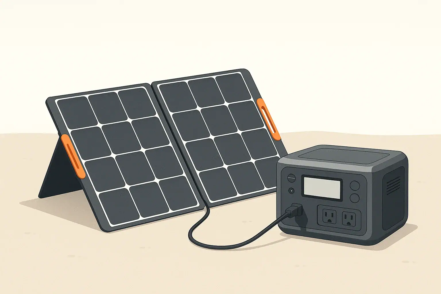
portable power station charging from solar panels outdoors

For most small portable power stations, parallel wiring is usually safer and more forgiving, while larger units often benefit from series or series-parallel wiring if their specs allow it. The best choice depends on your power station’s maximum solar voltage, current, and watt limits, plus how many panels you use and how shaded your setup is.

This guide explains solar panel series vs parallel wiring in plain language, focusing on portable power stations, solar generators, and small off-grid setups. You will see how each wiring method changes voltage and current, how to match panel strings to your power station input, and how shade, cable length, and temperature affect real charging speed.

By the end, you will be able to look at a panel label and a power station spec sheet and quickly decide whether series, parallel, or a mix of both makes the most sense for your camping, RV, or backup power system.

What Series and Parallel Mean for Portable Power Stations

When you combine solar panels to charge a portable power station, you can wire them in series, parallel, or a combination of both. These wiring choices change the voltage (V) and current (A) that reach the solar input, even if the total wattage (W) of the array stays similar in ideal sun.

Understanding this matters because every power station has hard limits, such as:

  • Maximum solar input voltage (V)
  • Maximum solar input current (A), sometimes
  • Maximum solar input power (W)

If your series voltage goes too high, you can trip protections or damage the input. If your parallel current goes too high, you can overheat cables or connectors. Getting series vs parallel right helps you:

  • Charge as fast as the power station allows, without exceeding limits
  • Handle shade and mixed conditions more predictably
  • Use reasonable cable sizes and lengths
  • Maintain safety margins in hot and cold weather

For portable systems used at home, in vehicles, or at campsites, this is usually less about squeezing out every last watt and more about staying within safe operating windows while keeping the setup simple to use.

How Series and Parallel Wiring Work

direct current (DC) is produced by solar panels. When you connect multiple panels, you can decide whether to add their voltages (series) or their currents (parallel). The basic rules are simple, but the implications for a power station are important.

Series wiring: higher voltage, same current

In a series connection, you connect the positive lead of one panel to the negative lead of the next, forming a chain. The remaining free positive and negative leads go to the power station’s solar input.

  • Voltage adds (Vtotal ≈ V1 + V2 + …)
  • Current stays roughly the same as one panel
  • Power ≈ Vtotal × I (same total watts as parallel in ideal sun)

Example: two similar 100 W panels, each with about 20 V and 5 A under load:

  • Series: ~40 V and ~5 A → ~200 W potential in good sun

This higher voltage can be helpful when:

  • Your power station allows a higher input voltage window
  • You need longer cable runs and want to reduce voltage drop
  • You are building a larger roof-mounted or semi-permanent array

The trade-off is that you must pay close attention to the maximum voltage rating of the power station, including cold-weather voltage increases.

Parallel wiring: same voltage, higher current

In a parallel connection, all panel positives are tied together, and all panel negatives are tied together. The combined positive and negative then go to the solar input.

  • Voltage stays roughly the same as one panel
  • Current adds (Itotal ≈ I1 + I2 + …)
  • Power ≈ V × Itotal (again, similar watts in ideal sun)

Using the same example panels:

  • Parallel: ~20 V and ~10 A → ~200 W potential in good sun

Parallel wiring tends to be more compatible with smaller power stations because the voltage stays low. However, the higher current means:

  • Cables and connectors must be rated for more amps
  • Voltage drop over long cables becomes more noticeable
  • Heat in undersized wiring can become a safety issue
Table 1. Series vs parallel for portable power stations – Example values for illustration.
Factor Series wiring Parallel wiring
Resulting voltage Adds with each panel; can approach input voltage limit Similar to a single panel; usually easier to keep within limits
Resulting current Similar to one panel; often easier on connectors Adds with each panel; can approach cable and connector ratings
Performance in partial shade One weak panel can drag down the whole string Each panel contributes more independently; shade impact is localized
Long cable runs Higher voltage reduces percentage loss from voltage drop Lower voltage is more affected by resistance in long cables
Risk focus More risk of exceeding max voltage, especially in cold weather More risk of overcurrent and cable heating
Typical use Larger or mid-sized stations with higher voltage input ratings Small to mid-sized stations with modest voltage limits

Real-World Examples and Simple Calculations

Once you understand the basics, the next step is to run quick checks using the panel labels and your power station manual. These simple examples show how series vs parallel changes what the device sees.

Example 1: Two 100 W panels and a small power station

Assume each 100 W panel is labeled approximately:

  • VOC (open-circuit voltage): 22 V
  • Vmp (voltage at max power): 18 V
  • Imp (current at max power): 5.5 A

Your small power station lists:

  • Max solar input voltage: 24 V
  • Max solar input power: 150 W

Series wiring of two panels:

  • String VOC ≈ 22 V + 22 V = 44 V → exceeds 24 V limit
  • Not safe for this device, even if it might appear to work briefly

Parallel wiring of two panels:

  • VOC stays ≈ 22 V → within the 24 V limit
  • Imp ≈ 5.5 A + 5.5 A = 11 A
  • Panel array could deliver ~18 V × 11 A ≈ 200 W, but the power station will cap at 150 W

In this case, parallel is clearly the better and safer choice.

Example 2: Four 100 W panels and a mid-sized power station

Now assume the same panels, but your power station lists:

  • Max solar input voltage: 60 V
  • Max solar input current: 15 A
  • Max solar input power: 400 W

Option A – All four in parallel:

  • VOC ≈ 22 V
  • Imp ≈ 4 × 5.5 A = 22 A → exceeds 15 A limit

Option B – Two in series, then those two strings in parallel (series-parallel):

  • Each series pair: VOC ≈ 44 V, Imp ≈ 5.5 A
  • Two series strings in parallel: VOC ≈ 44 V, Imp ≈ 11 A
  • Array power at max: ~18 V × 2 × 5.5 A × 2 ≈ 400 W

This series-parallel arrangement keeps both voltage and current within limits while allowing the power station to use close to its full 400 W solar capacity.

Estimating charge time

A quick way to estimate solar charge time in good sun is:

  • Charge time (hours) ≈ Battery capacity (Wh) ÷ Usable solar input (W)

For example, a 1000 Wh power station with about 300 W of real-world solar input might charge in roughly 3–4 hours of strong sun, after accounting for losses and conditions.

Table 2. Example setups and likely wiring choice – Example values for illustration.
Use case Typical gear Likely wiring Reasoning
Small backup at home 1–2 portable panels, small power station Parallel Low voltage limits; buildings and trees cause partial shade
Remote work setup 2–4 rigid panels, mid-sized station Series or series-parallel Higher voltage input, longer cable runs from yard to indoors
Weekend camping 1–2 folding panels, compact station Parallel Panels often moved and partly shaded; simple plug-and-play
RV or van roof array 4+ roof-mounted panels, larger station Series-parallel Balance voltage and current within controller limits

Common Mistakes and Troubleshooting Cues

Most problems people see when combining solar panels for a power station come from wiring choices that do not match the device’s specs or from conditions like shade and temperature. Recognizing the symptoms helps you correct them quickly.

Mistake 1: Exceeding maximum input voltage

What it looks like:

  • Power station refuses to start solar charging
  • Display shows an error code or “over-voltage” message
  • Charging works on warm days but fails on cold, bright mornings

Likely cause: Too many panels in series, pushing VOC near or above the rated maximum, especially in cold weather when voltage rises.

Fix:

  • Reduce the number of panels in series
  • Switch to parallel or series-parallel to stay within the voltage window
  • Leave extra voltage headroom instead of designing right at the limit

Mistake 2: Exceeding current limits or using undersized wiring

What it looks like:

  • Cables feel warm or hot to the touch during peak sun
  • Connectors look discolored or show signs of melting
  • Power station input occasionally cuts out under strong sun

Likely cause: Too many panels in parallel or thin extension cables that cannot handle the combined current.

Fix:

  • Check the power station’s maximum input current rating
  • Reduce the number of parallel panels or move to series-parallel
  • Use thicker, outdoor-rated solar cable sized for the expected amps

Mistake 3: Mismatched panels in series

What it looks like:

  • Array output is noticeably lower than expected
  • One panel is consistently cooler or warmer than the others

Likely cause: Combining panels with very different wattages or current ratings in the same series string. The lowest-performing panel limits the string current.

Fix:

  • Use panels of similar voltage and current ratings in each series string
  • If you must mix panels, do so in parallel where the impact is smaller

Mistake 4: Underestimating shade and panel placement

What it looks like:

  • Solar input drops sharply when a tree, antenna, or roof rack casts a shadow
  • Series strings lose most of their output when only one panel is shaded

Likely cause: Series wiring in a location with frequent partial shading, or panels placed at different angles.

Fix:

  • Favor parallel wiring where shading is unavoidable
  • Reposition portable panels to keep them in consistent sun
  • On roofs, plan string layouts to avoid regular shade from vents or racks

Quick troubleshooting checklist

  • Verify polarity on all connectors (positive to positive, negative to negative)
  • Check panel labels and recalculate string voltage and current
  • Test each panel alone to confirm it is producing power
  • Inspect all cables and connectors for damage, corrosion, or overheating

Safety Basics for Series and Parallel Solar Wiring

Portable power stations include built-in protections, but they cannot compensate for wiring that ignores basic electrical limits. A few habits go a long way toward safe, reliable operation.

Respect every component rating

  • Panels: Do not exceed their rated series fuse or connect them in ways the manufacturer does not support.
  • Cables: Use wire gauge that matches or exceeds the maximum expected current.
  • Connectors and adapters: Choose parts rated for outdoor DC use and the current of your array.
  • Power station input: Never exceed the published voltage or wattage limits.

Think about voltage and shock risk

As you add more panels in series, the open-circuit voltage can climb well above typical low-voltage DC thresholds. While still lower than household AC, higher DC voltage can increase shock risk and arc potential if connectors are mishandled.

  • Avoid touching bare conductors when panels are in sun
  • Make and break connections with panels covered or out of direct sunlight when possible
  • Do not work on wet connectors or cables

Use fuses or disconnects where appropriate

Many simple plug-in setups rely only on the power station’s internal protections. For larger or semi-permanent arrays, adding basic external protection is common practice:

  • Inline fuses sized for the string current
  • DC disconnect switches to isolate the array before rewiring

If you are unsure how to size or place these components, consulting a qualified electrician or solar professional is recommended, especially for RVs and long-term off-grid systems.

Keep the power station protected from weather and heat

  • Operate the power station in a dry, shaded location
  • Avoid enclosing it in tight compartments without ventilation
  • Keep air vents clear during both charging and discharging

Long-Term Use, Maintenance, and Storage

Series vs parallel wiring is only part of keeping your solar and power station setup working well over time. Basic care of panels, cables, and the power station itself helps maintain performance.

Panel care

  • Cleaning: Gently remove dust, pollen, and debris with water and a soft cloth or sponge. Avoid abrasive cleaners.
  • Inspection: Check for cracks, delamination, or damaged junction boxes that could affect output or safety.
  • Mounting: For roof-mounted panels, periodically verify that brackets and fasteners remain tight.

Cable and connector maintenance

  • Inspect cables for cuts, flattened sections, or exposed conductors
  • Keep connectors dry and off the ground where possible
  • Replace any connector that shows signs of overheating or corrosion

Power station storage

  • Store the unit in a cool, dry place when not in use
  • Follow the manufacturer’s guidance for long-term battery storage state-of-charge
  • Top up the battery periodically if the unit sits unused for months

Seasonal adjustments

  • In winter, expect higher panel voltage and lower overall output hours
  • In summer, check that cables and connectors are not overheating during long sunny days
  • Adjust panel tilt or placement seasonally if practical to improve production

Practical Takeaways and Specs to Look For

Choosing between solar panel series vs parallel wiring for a portable power station is mostly about matching your panels to the device’s input window and your environment.

  • Smaller power stations with low voltage limits usually favor parallel wiring.
  • Mid-sized and larger units with higher voltage inputs often work best with series or series-parallel.
  • Shady or cluttered locations tend to favor parallel; open, sunny spaces can benefit from series.
  • Long cable runs are easier to manage with higher voltage (series), as long as you stay within limits.

Specs to look for before deciding on series or parallel

  • From the power station:
    • Maximum solar input voltage (V) and any stated minimum voltage
    • Maximum solar input current (A), if listed
    • Maximum solar input power (W)
    • Recommended input voltage range for best MPPT performance, if specified
    • Supported connector types and any included adapters
  • From each solar panel:
    • VOC (open-circuit voltage)
    • Vmp (voltage at maximum power)
    • Imp (current at maximum power)
    • Recommended maximum series fuse rating
  • For your wiring plan:
    • Series string VOC: VOC × number of panels in series, with cold-weather headroom
    • Total array current: sum of Imp for parallel strings
    • Cable gauge sized for the highest current path
    • Expected shade patterns and whether panels can be placed together in full sun

If you can quickly answer these points from your labels and manual, you have everything you need to choose series, parallel, or a mix of both in a way that charges efficiently while staying safely inside the limits of your portable power station.

Frequently asked questions

Which power station and panel specifications matter most when deciding between series and parallel wiring?

Check the power station’s maximum solar input voltage, maximum input current (if listed), and maximum input power. From the panels, note V_OC, V_mp, and I_mp so you can calculate string V_OC and array current and ensure you stay within the station’s limits.

What common wiring mistake causes cable overheating?

Using too many panels in parallel without matching the cable gauge to the higher combined current often causes overheating. The fix is to either reduce parallel strings, reconfigure to series-parallel, or use thicker, outdoor-rated wiring sized for the expected amps.

Is wiring solar panels in series or parallel safer from a general safety perspective?

Neither is inherently safer; each has distinct hazards: series raises voltage which can increase shock and over-voltage risk for the power station, while parallel increases current which can overheat cables and connectors. Choose the method that keeps both voltage and current inside component ratings and use proper fusing and disconnects where appropriate.

How does partial shading affect a series string compared with a parallel array?

In a series string one shaded panel can reduce the current for the entire string, significantly lowering output. In parallel arrays shading tends to affect only the shaded panel’s contribution, making parallel more tolerant of mixed shade conditions.

Will rewiring panels to series always increase charging speed?

Not always — higher series voltage can reduce voltage drop and be beneficial for long runs or higher-voltage inputs, but if it exceeds the power station’s voltage limit it won’t work. Charging speed depends on staying within the station’s voltage, current, and wattage limits and on real-world conditions like sun, temperature, and MPPT efficiency.

Should I add fuses or a DC disconnect for a portable solar setup?

For small, short-term portable setups the power station’s internal protections are often sufficient, but fuses and a disconnect are recommended for larger or semi-permanent arrays. Inline fuses sized to the expected string current and a DC disconnect help isolate the array for safe maintenance and provide an extra layer of protection.

MPPT vs PWM in Portable Power Stations: Real Charging Differences Explained

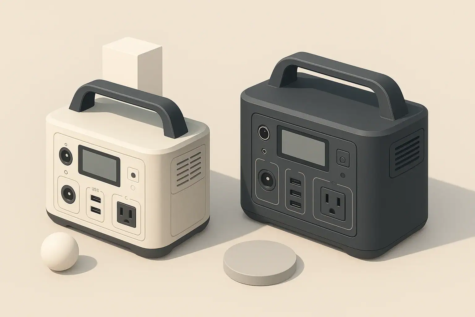
Two portable power stations shown side by side for comparison

MPPT solar charging usually gives a portable power station noticeably faster and more consistent charging than PWM from the same solar panels. In real life that means shorter charge times, better performance in weak sun, and more flexibility in how you wire and place your panels.

This guide explains what MPPT and PWM actually do inside a portable power station, how much difference they make in watt-hours and hours of charging time, and when a simpler PWM input is still good enough. You will see plain-language examples, simple calculations, and typical use cases like camping, RV setups, and emergency backup power.

By the end, you will know how to read solar input specs, avoid common mistakes that slow charging, and decide whether it is worth paying more for MPPT in your next portable power station or solar generator.

What MPPT and PWM Mean and Why They Matter

A portable power station that accepts solar needs a built-in solar charge controller. That controller is almost always one of two types: PWM (pulse width modulation) or MPPT (maximum power point tracking). Both protect the battery and manage charging, but they do it in different ways that directly affect how much energy you actually store each day.

In simple terms:

  • PWM is simpler and cheaper but wastes more of the panel’s potential power, especially when panel voltage is much higher than the battery voltage.
  • MPPT is more advanced and usually harvests about 15–30% more energy from the same panels, especially in cold weather, weak sun, or partial shade.

Why this matters in real life:

  • Charging speed: MPPT can turn a “barely keeps up” solar setup into one that reliably refills the battery in a day of sun.
  • Panel flexibility: MPPT lets you use higher-voltage panels or series wiring to reduce cable losses.
  • Reliability of power: If you depend on solar for fridges, communication gear, or medical devices, the extra harvest from MPPT can be the difference between full and flat by morning.

If you only use solar occasionally, PWM can still be acceptable. But if solar is your main charging method, understanding MPPT vs PWM helps you choose a portable power station that matches your expectations.

Key Concepts: How MPPT and PWM Work With Solar Panels

To understand why MPPT usually wins, it helps to look at what the controller does with voltage and current between the solar panels and the battery inside your portable power station.

What the Solar Charge Controller Actually Does

Inside the power station, the solar charge controller:

  • Limits voltage and current to protect the battery from overcharging.
  • Manages charging stages for battery health (fast charge, then slower topping, then maintaining).
  • Tries to use the available solar power as effectively as its design allows.

The difference is how PWM and MPPT “use” the panel’s voltage and current.

PWM: Simple Voltage Matching

A PWM controller connects the panel to the battery and rapidly switches the connection on and off to control average current. It effectively drags the panel voltage down close to the battery voltage.

  • If the panel’s best operating voltage (Vmp) is much higher than the battery voltage, the extra voltage is mostly lost.
  • The panel is forced to run away from its most efficient point on the voltage–current curve.
  • Electronics are simple and inexpensive, which is why PWM often appears in smaller or budget power stations.

MPPT: Actively Finding Maximum Power

An MPPT controller continuously measures panel voltage and current and adjusts the operating point to stay near the panel’s maximum power point.

  • It runs the panel at or near Vmp, where voltage and current multiply to the highest wattage.
  • A DC–DC converter inside steps the higher panel voltage down to the battery voltage while increasing current.
  • As sunlight changes (clouds, angle, temperature), it retunes the operating point to keep power output close to the maximum available.

Energy Harvest in Numbers

Under many real-world conditions, MPPT can harvest roughly 15–30% more energy than PWM from the same panels. The exact gain depends on:

  • How much higher the panel voltage is than the battery voltage.
  • Temperature (panels run at higher voltage when cold).
  • Cloud cover, shade patterns, and time of day.
  • Cable length and wire thickness (voltage drop).

In cold, clear conditions with higher-voltage panels, the gain can be on the higher end. In very hot conditions with low panel voltage and short cables, the gain can be smaller but usually still present.

Real-World Examples and Typical Use Cases

Numbers are easier to understand with concrete examples. The following scenarios use rounded values to show how MPPT vs PWM changes daily energy harvest and charging time.

Example 1: Single 100 W Panel and a Mid-Size Power Station

Assume:

  • Solar panel: 100 W, Vmp 18 V, Imp 5.5 A.
  • Battery charging voltage inside the power station: about 13 V.
  • Good sun: 5 hours of strong midday-equivalent sunlight.

Approximate power into the battery:

  • PWM: Panel is pulled to about 13 V. Power ≈ 13 V × 5.5 A ≈ 71.5 W.
  • MPPT: Panel runs near 18 V. Power ≈ 18 V × 5.5 A ≈ 99 W, minus some conversion loss.

Over 5 sun hours:

  • PWM: about 70 W × 5 h ≈ 350 Wh into the battery.
  • MPPT: about 90–95 W × 5 h ≈ 450–475 Wh into the battery.

On a 500 Wh power station, that can mean the difference between almost full in one day (MPPT) versus needing part of a second day (PWM).

Setup Controller Type Effective Panel Power (W) Daily Energy (Wh, 5 sun hours) Approx. Time to Charge 500 Wh
100 W panel PWM ~70 W ~350 Wh About 1.4 days of good sun
100 W panel MPPT ~90–95 W ~450–475 Wh About 1 day of good sun
200 W panels PWM ~140 W ~700 Wh About 0.8 day of good sun
200 W panels MPPT ~180–190 W ~900–950 Wh About 0.6 day of good sun
Typical impact of MPPT vs PWM on daily energy harvest and charge time. Example values for illustration.

Example 2: Long Cable Run to a Sunny Spot

Imagine your power station sits inside a van or tent, but your panels are 10–15 meters away in full sun.

  • PWM setup: Panels wired for low voltage (close to battery voltage). Current is relatively high, so voltage drop in the long cable eats into your power. You may lose 10% or more unless you use thick, heavy cable.
  • MPPT setup: Panels wired in series for a higher voltage (within the power station’s limit). Current is lower, so the same cable has less voltage drop and you deliver more power to the controller.

In practice, this can be the difference between the station finishing its charge before sunset versus still being short by evening.

Example 3: Cloudy or Partially Shaded Days

On days with moving clouds or partial shade:

  • PWM: Panel voltage and current both sag, and the controller simply follows the battery voltage. Output can drop sharply and stay low until conditions improve.
  • MPPT: The controller re-scans the panel’s voltage–current curve and finds a new point that still delivers as much power as conditions allow. You may not get full rated power, but you typically get more than with PWM.

If you are relying on solar to run a fridge or communication gear in poor weather, this extra harvest can be very noticeable over a multi-day trip.

Common Mistakes and Troubleshooting Slow Solar Charging

Many “my solar is not working” problems turn out to be configuration issues rather than defective hardware. MPPT and PWM each have their own common pitfalls.

Frequent Mistakes With PWM Inputs

  • Using very high-voltage panels: A PWM controller will drag the panel voltage down to near battery voltage and throw away the extra. The result: you paid for panel wattage you can never use.
  • Long, thin cables: Because current is relatively high at low voltage, thin or very long cables cause large voltage drops and wasted power.
  • Overestimating charge speed: People often size panels based on the printed wattage, then discover the PWM controller only delivers 60–75% of that into the battery.

Frequent Mistakes With MPPT Inputs

  • Exceeding input voltage: Wiring too many panels in series can push the solar input above the controller’s maximum voltage rating, risking shutdown or damage.
  • Ignoring shading patterns: One panel in deep shade in a series string can pull the whole string down. MPPT cannot create power that the panels are not producing.
  • Expecting miracles in very poor sun: MPPT is more efficient, but it still needs a minimum amount of light. In heavy overcast, both PWM and MPPT will produce limited power.

Simple Troubleshooting Cues

If your portable power station charges slowly from solar, work through these checks:

  • Panel orientation: Is the panel broadly facing the sun, not lying flat or shaded?
  • Cables and connectors: Are all plugs fully seated, with no bent pins or damaged insulation?
  • Input limits: Is the total panel wattage and voltage within the power station’s stated solar input range?
  • Battery state: Charging always slows down as the battery nears full. Compare speed at 20–50% charge versus 90–100%.
  • Controller type vs expectation: If your unit uses PWM, mentally reduce the panel’s rated watts by around 25–35% when estimating charge times.
Symptom Likely Cause Quick Check or Fix
Solar input shows much lower watts than panel rating PWM controller or poor sun angle Confirm controller type; re-aim panel toward sun and compare midday readings
Solar input drops to zero intermittently Loose connector or panel cable strain Inspect and reseat all connectors; reduce cable tension
Unit will not accept solar at all Panel voltage outside allowed range Measure open-circuit panel voltage; compare with solar input spec
Panels far away, charging slower than expected Voltage drop in long, thin cables Use thicker cable or higher-voltage array with MPPT (within limits)
Good sun but sudden large power dips Moving shade from trees, poles, or people Watch panel surface for shadows; reposition if needed
Typical solar charging problems and quick diagnostic steps. Example values for illustration.

Safety Basics for Solar Charging and Controllers

Whether your portable power station uses MPPT or PWM, safe solar charging comes down to staying within the unit’s limits and handling DC power carefully.

Respect Voltage and Power Limits

  • Do not exceed maximum solar input voltage: Going above the rated input voltage can instantly damage the controller. This is especially important when wiring panels in series for an MPPT input.
  • Stay within maximum solar wattage: Oversizing the array far beyond the rated wattage can cause the unit to run hot or shut down. A modest amount of oversizing is often tolerated, but check the specs.
  • Match connectors and polarity: Reversed polarity on DC connectors can damage internal electronics. Always double-check markings before plugging in.

Manage Heat and Ventilation

  • Keep the power station ventilated: Both MPPT and PWM controllers generate heat while converting power. Do not cover the unit or block vents while charging at high solar input.
  • Avoid direct hot sun on the unit: It is fine for panels to be in full sun, but the power station itself will run cooler and last longer if shaded and ventilated.

Safe Handling of Panels and Cables

  • Secure panels in wind: A loose panel can flip, damage connectors, or injure someone.
  • Protect cables from pinch points: Avoid running cables through doors or windows that can crush insulation.
  • Disconnect safely: If you need to unplug panels under load, grip connectors firmly and avoid pulling on the cable itself.

These practices apply regardless of controller type. MPPT does not inherently require more safety precautions than PWM, but higher-voltage arrays for MPPT deserve extra attention to correct wiring and insulation.

Long-Term Use, Maintenance, and Seasonal Considerations

Good habits around storage, cleaning, and seasonal use help both MPPT and PWM systems perform closer to their potential over time.

Panel Care and Cleaning

  • Keep panel surfaces clean: Dust, pollen, and bird droppings reduce output. A soft cloth and clean water usually suffice.
  • Inspect for micro-cracks: After drops or impacts, check panels for broken glass or delamination, which can lower performance or create hot spots.

Battery and Controller Health Over Time

  • Avoid constant 0–100% cycles: Deep cycling every day can age the battery faster. If possible, operate between roughly 20–80% state of charge for daily use.
  • Store partially charged: For long-term storage, many manufacturers recommend storing around 40–60% charge and topping up every few months.
  • Monitor for unusual heat: During high solar input, the unit should be warm but not excessively hot. Persistent overheating suggests you are pushing limits or blocking ventilation.

Seasonal Adjustments

  • Winter: Short days and low sun angles reduce total energy, but cold panels run at higher voltage. MPPT benefits tend to be larger in these conditions.
  • Summer: Longer days but hotter panels mean slightly lower voltage. Expect both MPPT and PWM to run closer to their rated power at midday, with MPPT still ahead.
  • Travel and storage: When transporting, protect panel faces and avoid sharp bends in cables to prevent long-term damage that silently reduces output.

Practical Takeaways and Specs to Look For

Choosing between MPPT and PWM in a portable power station comes down to how much you rely on solar and how constrained your environment is.

  • Heavy or primary solar use: MPPT is usually worth it for campers, RV users, off-grid cabins, and anyone running fridges or critical loads from solar.
  • Occasional or backup solar use: PWM can be acceptable if you mostly charge from AC or vehicle power and just want solar as a slow top-up.
  • Space-limited setups: If you cannot add more panel area, MPPT’s extra 15–30% harvest is effectively “free panel upgrade” from the same footprint.

Specs to Look For on the Data Sheet

When comparing portable power stations, scan the solar section of the spec sheet for these details:

  • Controller type: Look for explicit wording like “MPPT solar charge controller.” If nothing is mentioned, assume PWM or confirm in the manual.
  • Maximum solar input power (W): This tells you the largest practical array size. More watts usually means faster charging if you can supply them.
  • Solar input voltage range (V): A wider range and a higher maximum voltage make it easier to wire panels in series and reduce cable losses, especially with MPPT.
  • Maximum solar input current (A): Important when using low-voltage, high-current arrays or PWM inputs where current is naturally higher.
  • Connector type and rating: Ensure the physical connector and adapter cables can safely handle the expected current.
  • Published solar charging times: Compare claimed charge times from a stated panel wattage. If they seem optimistic, remember that PWM will deliver less than the panel’s printed wattage.

Align these specs with how you plan to use the power station: how often you see full sun, how much panel area you can deploy, how far panels sit from the unit, and how critical it is that the battery reaches full each day. With that information, the choice between MPPT and PWM becomes a practical decision instead of a confusing acronym.

Frequently asked questions

Which solar input specifications should I check when choosing a portable power station?

Check the controller type (MPPT or PWM), the maximum solar input power (watts), the supported input voltage range, and the maximum input current. Also confirm connector types and any published solar charging times so you can match the station to your panel array and expected conditions.

Why is my solar charging much slower than the panel’s rated wattage?

Slower charging is often due to mismatches between panel Vmp and the controller (especially with PWM), cable voltage drop, shading, or the battery already being near full. Verify wiring, orientation, and controller type, and measure input watts at midday to isolate the cause.

Are there safety risks when wiring panels for MPPT or using higher-voltage arrays?

Yes—wiring panels in series can raise open-circuit voltage above the controller’s maximum and risk damage or failure. Always stay within the power station’s voltage and wattage limits, use proper insulation and connectors, and avoid exposing the unit to blocked ventilation or extreme heat while charging.

How much faster will MPPT charge compared with PWM in real use?

MPPT typically harvests about 15–30% more energy than PWM under many real-world conditions, which translates to noticeably faster charge times. The exact gain depends on panel voltage relative to battery voltage, temperature, shade, and cable losses.

Can I mix different solar panels or combine series and parallel wiring with a portable power station?

Mixing panels with different voltages or currents can cause mismatches that reduce output; it’s best to use panels with similar Vmp and current ratings. Series wiring increases array voltage (watch the controller’s max voltage) while parallel wiring increases current (watch max input current), so plan wiring to stay within limits.

How important are cable length and wire gauge for solar charging efficiency?

Very important—long or thin cables cause voltage drop and reduce power at the controller, especially with low-voltage (PWM-style) setups. Use thicker cable or run panels at higher voltage (within the controller’s allowed range) to reduce losses and improve delivered power.

AC vs DC Power: Maximize Portable Power Station Efficiency and Runtime

Isometric illustration of two portable power stations

To maximize runtime, use DC power whenever your devices allow it and reserve AC power for appliances that truly need a household-style outlet. Every time your portable power station converts DC battery energy into AC and back again, you lose usable capacity and shorten runtime.

This guide explains AC vs DC power in plain language, shows where energy is lost in a portable power station, and walks through realistic examples and calculations. You will see how different connection choices change runtime, what numbers on the spec sheet matter, and how to avoid common mistakes that quietly waste power.

Whether you use a power station for camping, vanlife, home backup, or medical and work equipment, understanding how AC and DC behave in this context lets you plan loads, choose the right outputs, and get more hours of reliable power from the same battery size.

AC vs DC Power in Portable Power Stations and Why It Matters

Portable power stations store energy in batteries as direct current (DC). To run typical household appliances, they use an internal inverter to convert that DC into alternating current (AC) that looks like wall power. Many smaller devices, however, can run directly from DC outputs such as USB or 12 V ports.

The key difference for runtime is simple: every conversion step wastes some energy as heat. DC devices powered from a DC port usually get more runtime from the same battery than the same devices powered through the AC inverter. When you power an AC device that internally converts AC back to DC (like most electronics), you often have two or more conversion stages.

Understanding the path from battery to device helps you decide:

  • Which port to use (AC outlet vs DC output)
  • How many devices you can run at once
  • How long your battery is likely to last under different loads

Once you see where losses occur, you can make small connection and usage changes that add up to hours of extra runtime.

Key Concepts: How AC and DC Power Flow Through a Power Station

Inside a portable power station, energy moves through several stages from the battery to your devices. Each stage has an efficiency rating that affects how much of the stored energy is actually delivered.

Direct Current (DC) Path

DC power flows in one direction and is the native form of energy in the battery. Common DC outputs include:

  • USB-A and USB-C ports for phones, tablets, and laptops
  • 12 V car-style sockets for fridges, fans, and pumps
  • Barrel or high-current DC ports for dedicated DC appliances

When you use these outputs, the power station may use DC-DC converters to adjust the voltage (for example, from a higher battery voltage down to 5 V USB). These converters are usually very efficient, especially near their rated load.

Alternating Current (AC) Path

AC power alternates direction and is what you get from household wall outlets. To provide this, the power station uses an inverter to convert DC battery power into AC at a standard voltage and frequency. This allows you to run devices such as:

  • Laptops with AC bricks and desktop computers
  • Small kitchen appliances, tools, and entertainment gear
  • Some medical or specialty devices that specify AC input only

Inverters are less efficient than DC-DC converters and have additional standby losses whenever they are turned on, even with no load connected.

Where Energy Is Lost

Energy losses primarily occur in these stages:

  • Battery round-trip losses when charging and discharging
  • DC-DC conversion losses when stepping voltage up or down
  • Inverter losses when converting DC to AC
  • Device-side losses in chargers, adapters, and internal power supplies

Typical efficiency ranges under realistic loads are:

  • Battery round-trip efficiency: about 85%–95%
  • DC-DC conversion: about 90%–98%
  • Inverter conversion: about 85%–95%, often worse at very low or very high loads
Power path Typical components Approximate overall efficiency When to use
Battery → DC-DC → Device Battery, internal DC-DC converter, phone or laptop charger 80%–90% (battery × DC-DC × device losses) Phones, tablets, DC lights, 12 V fridge, USB-C laptops
Battery → Inverter (AC) → Device Battery, inverter, AC power brick or appliance 70%–85% (battery × inverter × device losses) Appliances that require AC only, tools, some medical devices
Battery → Inverter (AC) → Device → Internal DC Battery, inverter, device’s internal AC-DC supply 65%–80% (extra AC-DC stage inside device) Electronics with built-in power supplies, monitors, routers
Comparison of common power paths in a portable power station. Example values for illustration.

Runtime Estimation Formula

You can estimate runtime with a simple equation using watt-hours (Wh) and watts (W):

Estimated runtime (hours) = (Battery Wh × usable battery fraction × system efficiency) ÷ load W

Where:

  • Battery Wh is the rated capacity of the battery pack
  • Usable battery fraction accounts for the fact that most systems do not use 100% of the rated capacity (often 0.85–0.95)
  • System efficiency includes inverter or DC-DC conversion and device-side losses
  • Load W is the actual power draw of your device or devices

Real-World Examples: How AC vs DC Changes Runtime

Seeing actual numbers makes the impact of AC vs DC power much clearer. The following examples assume a 1,000 Wh portable power station with 90% usable capacity (0.90) and typical efficiencies.

Example 1: Charging a Laptop

Assume the laptop draws 60 W while charging.

  • Via AC inverter: inverter efficiency 90%, laptop charger 90%
  • Via USB-C PD (DC): DC-DC efficiency 95%, laptop charging circuit 95%

Approximate system efficiency:

  • AC path: 0.90 (battery) × 0.90 (inverter) × 0.90 (charger) ≈ 0.73
  • DC path: 0.90 (battery) × 0.95 (DC-DC) × 0.95 (charger) ≈ 0.81

Estimated runtime:

  • AC: (1,000 Wh × 0.73) ÷ 60 W ≈ 12.2 hours
  • DC: (1,000 Wh × 0.81) ÷ 60 W ≈ 13.5 hours

Simply switching from AC to DC gains more than an hour of runtime for the same battery.

Example 2: Running a 12 V Fridge

Assume an efficient 12 V fridge averages 45 W over time (including compressor cycling).

  • 12 V DC socket: DC-DC efficiency about 95%
  • Through AC adapter: inverter 90%, fridge AC adapter 90%

Estimated runtime:

  • DC: (1,000 Wh × 0.90 × 0.95) ÷ 45 W ≈ 19.0 hours
  • AC: (1,000 Wh × 0.90 × 0.90 × 0.90) ÷ 45 W ≈ 16.2 hours

Using the native DC input for a DC appliance can add several hours of cooling on the same charge.

Example 3: Multiple Small Gadgets at Once

Consider charging three phones (10 W each) and one tablet (15 W) for a total of 45 W.

  • All via USB ports: DC-DC at about 95% efficiency
  • All via AC chargers: inverter 88% at light load, chargers 90%

Estimated runtime:

  • DC: (1,000 Wh × 0.90 × 0.95) ÷ 45 W ≈ 19.0 hours
  • AC: (1,000 Wh × 0.90 × 0.88 × 0.90) ÷ 45 W ≈ 15.8 hours

Light AC loads are often less efficient because inverter overhead becomes a larger share of total power.

Scenario Connection type Approx. load (W) Estimated runtime (1,000 Wh battery)
Laptop charging AC inverter 60 ≈ 12.2 hours
Laptop charging USB-C DC 60 ≈ 13.5 hours
12 V fridge 12 V DC socket 45 (average) ≈ 19.0 hours
12 V fridge AC adapter 45 (average) ≈ 16.2 hours
3 phones + 1 tablet USB DC 45 total ≈ 19.0 hours
3 phones + 1 tablet AC chargers 45 total ≈ 15.8 hours
Illustrative runtimes for common AC vs DC usage patterns on a 1,000 Wh power station. Example values for illustration.

Common Mistakes and Troubleshooting Short Runtime

Many users think their power station is underperforming when the real issue is how loads are connected or measured. The following mistakes frequently shorten runtime in AC vs DC power setups.

Mistake 1: Powering DC Devices Through the AC Inverter

Devices like phones, tablets, some laptops, LED strips, and 12 V fridges typically run on DC internally. Using an AC adapter adds extra conversion stages. Symptoms include:

  • Noticeably shorter runtime than expected
  • Inverter fan running even with modest loads
  • Power station display showing higher output than device rating suggests

Fix: Use USB, 12 V, or dedicated DC outputs whenever the device supports them.

Mistake 2: Ignoring Inverter Idle Consumption

Some inverters draw tens of watts simply by being turned on. With only a few small gadgets plugged in, this idle draw can equal or exceed the devices themselves.

  • Symptom: Battery drains overnight even though only a small device (like a router or LED light) is running
  • Fix: Turn off the AC inverter when not needed, or move low-power devices to DC outputs.

Mistake 3: Underestimating Startup Surge and Motor Loads

Appliances with motors, compressors, or heating elements often draw a high inrush current at startup, then settle to a lower running wattage. This can stress the inverter and reduce efficiency.

  • Symptom: Inverter shuts down when a fridge, pump, or power tool starts, even though running watts seem within the rating
  • Fix: Check both continuous and surge watt ratings and avoid stacking several motor loads on the same power station.

Mistake 4: Relying Only on Label Wattage

Nameplate ratings are often maximum values, not typical usage. Some devices draw much less in real use, while others (like gaming laptops or induction cooktops) can spike above their nominal rating.

  • Symptom: Calculated runtime does not match real-world results
  • Fix: Use the power station’s display or a plug-in meter (where safe and appropriate) to observe actual watt draw under your typical use.

Mistake 5: Running the Battery in Extreme Temperatures

Cold temperatures reduce available capacity and increase internal resistance, while high heat can cause the system to throttle or shut down to protect itself.

  • Symptom: Runtime is much shorter on cold nights or very hot days than during mild weather
  • Fix: Keep the unit within its recommended operating temperature range and avoid leaving it in closed vehicles in extreme heat or cold.
Issue Likely cause Quick check Suggested action
Runtime much shorter than expected Extra AC conversions, inverter idle loss Compare AC vs DC watt readings on display Move compatible devices to DC outputs
Inverter shuts off when appliance starts Startup surge exceeds inverter rating Listen for click or error when device starts Use smaller appliance or higher-rated inverter
Battery drains overnight on small loads Inverter idle draw dominates Check display with AC on and no loads Turn off AC, use DC or timer where possible
Poor performance in cold weather Reduced battery capacity at low temperature Compare runtime at room temperature vs cold Keep unit insulated and within spec range
Display watts higher than device label Multiple devices, power factor, or surges Measure while device is actively used Recalculate runtime using measured watts
Typical runtime and shutdown issues when using AC vs DC power, with quick troubleshooting checks. Example values for illustration.

Safety Basics When Using AC and DC Power

Maximizing runtime should never come at the expense of safety. AC power in particular can be hazardous if used incorrectly, and DC circuits can deliver high current that causes overheating.

Respect Voltage and Current Limits

  • Do not exceed the continuous watt rating of the inverter or DC outputs.
  • Avoid running the inverter at its maximum rating for long periods; this increases heat and reduces efficiency.
  • Use appropriately rated cables for high-current DC loads, especially on 12 V outputs.

Use Proper Ventilation

  • Place the power station on a hard, flat surface with vents unobstructed.
  • Do not cover the unit with blankets, clothing, or gear while in use.
  • Allow extra space around the inverter side, where heat and fan exhaust are concentrated.

Keep Moisture and Conductive Debris Away

  • Keep the power station dry; avoid placing it directly on damp ground or near open water.
  • Prevent metal objects such as tools, jewelry, or loose hardware from contacting ports.
  • Do not operate the unit if the enclosure is damaged or cracked.

Safe Use of Extension Cords and Power Strips

  • Use cords rated for the load and length you need; undersized cords can overheat.
  • Avoid daisy-chaining multiple power strips or extension cords from the same AC outlet.
  • Keep cords fully uncoiled during high-load operation to reduce heat buildup.

Follow Device-Specific Guidance

  • Some medical devices and sensitive electronics require a clean AC waveform and stable voltage.
  • Check device documentation for requirements on AC vs DC power and acceptable input ranges.
  • When powering critical equipment, build in extra capacity and redundancy rather than running at the edge of ratings.

Long-Term Efficiency: Maintenance, Storage, and Usage Habits

Maintaining good efficiency over the life of a portable power station is not just about daily usage. How you store, charge, and cycle the battery also affects available runtime for both AC and DC loads.

Battery Care for Stable Runtime

  • Avoid leaving the battery at 0% or 100% state of charge for long periods.
  • For storage longer than a few weeks, keep the battery at a moderate charge level, typically around half to three-quarters full.
  • Charge the unit every few months during storage to prevent deep discharge.

Temperature Management Over Time

  • Store the power station in a cool, dry place out of direct sunlight.
  • Avoid long-term storage in vehicles where temperatures can swing widely.
  • Allow the unit to warm up gradually before heavy use if it has been stored in a cold environment.

Monitoring Efficiency Drift

  • Periodically repeat a simple runtime test with a known load (such as a fixed 100 W AC or DC load) to see if runtime is changing over time.
  • If you notice a significant drop in runtime with the same load, consider whether aging batteries, new standby devices, or inverter behavior are contributing.
  • Keep notes on typical runtimes for your core devices; this makes it easier to spot changes early.

Good Habits for AC vs DC Use

  • Default to DC outputs for everyday electronics and lighting.
  • Turn on the AC inverter only when you actually need AC appliances.
  • Group high-demand AC tasks (like cooking or power tools) into shorter sessions instead of spreading them out, to minimize idle inverter time.

Practical Takeaways and Specs to Look For

AC vs DC power choices can easily change your usable runtime by 10–30% or more. A few planning steps and the right specs make it easier to get reliable performance from your portable power station in any situation.

Key Takeaways for Everyday Use

  • Use DC outputs whenever possible for phones, tablets, laptops, lights, and 12 V appliances.
  • Reserve AC for devices that genuinely require a standard wall outlet.
  • Account for efficiency losses when estimating runtime, not just battery size.
  • Avoid leaving the inverter on with only tiny loads connected.
  • Plan around surge and continuous ratings when running motor or heating loads.

Specs to Look For on a Portable Power Station

When comparing or configuring portable power stations, pay close attention to these specifications and features that directly affect AC vs DC efficiency and runtime:

  • Battery capacity (Wh): Larger Wh means more stored energy. Compare devices using watt-hours, not just amp-hours.
  • Usable capacity or depth-of-discharge management: Systems that manage the battery to avoid deep discharge can provide consistent runtime and longer battery life.
  • Inverter continuous and surge ratings (W): Ensure both ratings comfortably exceed the combined AC loads you plan to run, including startup surges.
  • Inverter efficiency curve: Look for high efficiency at the load levels you will actually use (for example, 100–500 W for typical camping setups).
  • Inverter idle consumption: Lower no-load or standby draw helps when you run small AC loads or leave the unit on for long periods.
  • Number and type of DC outputs: Multiple USB-A, USB-C (especially high-power USB-C), and 12 V outputs make it easier to avoid unnecessary AC conversions.
  • DC output current limits: Check the maximum current or watt rating for each DC port to ensure it can support fridges, pumps, or other higher-draw DC devices.
  • Charge efficiency and input options: Efficient AC charging and solar/DC input help you refill the battery with less wasted energy.
  • Display accuracy: A clear, reasonably accurate display of watts in, watts out, and remaining capacity makes it easier to tune AC vs DC usage in real time.
  • Thermal management and operating temperature range: Better cooling and clear temperature specs help maintain efficiency and protect the battery.

By combining the right specifications with smart choices about when to use AC vs DC power, you can stretch every watt-hour further, reduce wasted energy, and get more practical work, comfort, and safety out of your portable power station.

Frequently asked questions

Which specs and features most affect AC vs DC efficiency and overall runtime?

Battery capacity in watt-hours, usable capacity or depth-of-discharge management, inverter efficiency and idle consumption, and the number and rating of DC outputs are the most important. Thermal management and an accurate display of watts in/out also help you run the system in its most efficient range.

Why shouldn’t I power DC devices through the AC inverter?

Powering a device via the inverter adds an extra DC→AC→DC conversion, which increases losses and shortens runtime. Using native DC outputs avoids that extra conversion and usually yields noticeably longer run times.

How can I safely power sensitive or medical equipment from a portable power station?

Check the equipment’s input requirements and confirm the power station can supply a clean waveform, the required voltage, and enough continuous and surge capacity. For critical or medical devices, follow device documentation, allow a safety margin in capacity, and consider redundant power sources when possible.

What quick steps give the biggest runtime gains in the field?

Use DC ports for everyday electronics, turn off the AC inverter when you don’t need it, group high-AC tasks into shorter sessions, and monitor actual watt draw rather than relying solely on nameplate ratings. Avoid operating in extreme temperatures and use appropriately rated cables for high-current DC loads.

How do startup surges and motor loads affect performance?

Devices with motors or compressors can draw a large inrush current at startup that may exceed the inverter’s surge rating and cause shutdowns. Verify both continuous and surge ratings, avoid stacking motor loads, and choose equipment with lower startup draws if possible.

How accurate are runtime estimates and how can I measure real-world runtime?

Estimates use typical efficiency assumptions and can differ from real use due to inverter idle draw, temperature, and device-side losses. For better accuracy, measure watts out with the power station display or a meter under your normal load and repeat a timed runtime test with that known load.

Pure Sine Wave vs Modified Sine Wave: What Matters for Your Portable Power Station

Isometric illustration of two portable power stations

For most portable power station users, a pure sine wave inverter is the safer and more compatible choice, while a modified sine wave unit is acceptable only for simple, non-sensitive loads. The difference between pure sine wave and modified sine wave affects what you can plug in, how efficiently the battery is used, and how much noise or heat your devices produce.

If you mainly power laptops, medical devices, refrigerators with electronic controls, or audio gear, prioritize a pure sine wave output that closely mimics utility power. If you only need to run basic lights or simple resistive heaters, a modified sine wave inverter can work but comes with more limitations. Understanding how these waveforms behave in real-world use helps you match your portable power station to your appliances and avoid costly mistakes.

What pure and modified sine waves mean, and why they matter

A portable power station stores energy as DC (direct current) in its battery, then uses an inverter to create AC (alternating current) at 120 V, 60 Hz. The shape of that AC waveform is what people mean by pure sine wave vs modified sine wave.

Pure sine wave inverters output a smooth, rounded waveform similar to grid power. Voltage rises and falls gradually, and the signal contains very little electrical noise. This is what most household electronics are designed for.

Modified sine wave (sometimes called quasi-sine or stepped square wave) inverters approximate a sine wave using flat steps. The voltage jumps abruptly between levels instead of following a smooth curve. This is cheaper to build but creates extra harmonics and electrical noise.

Why it matters:

  • Compatibility: Some devices simply will not start or will show error codes on a modified sine wave.
  • Efficiency and runtime: Sensitive electronics and motors often draw more power and run hotter on a modified sine wave, reducing battery runtime.
  • Noise and comfort: Buzzing, humming, and interference are more common with modified sine wave inverters.
  • Longevity and risk: Long-term use of the wrong waveform can shorten the life of motors, power supplies, and control boards.

Key technical concepts: how waveform type affects devices

You do not need to be an engineer to choose between pure and modified sine wave, but a few basic concepts help explain the trade-offs.

Waveform shape and harmonics

A pure sine wave has a single, smooth frequency at 60 Hz with very low total harmonic distortion (THD). A modified sine wave is made of flat segments and sharp corners, which introduce extra frequencies called harmonics. Devices with transformers, motors, or power factor correction circuits often react poorly to those harmonics.

In practice, this can mean:

  • Transformers and motors running hotter than normal.
  • Audio equipment picking up a background hum.
  • Digital power supplies working harder to filter the noisy input.

Voltage, frequency, and control electronics

Most portable power stations try to hold 120 V at 60 Hz, but waveform type changes how that energy is delivered over each cycle. Pure sine inverters usually control both voltage and frequency tightly, so devices with timing circuits, digital displays, and control boards behave as designed.

On a modified sine wave, the average voltage and frequency may be close to 120 V / 60 Hz, yet the sudden transitions can confuse or stress:

  • Microwave ovens with digital controls or inverter-based cooking.
  • Refrigerators and freezers with electronic control boards.
  • Battery chargers with power factor correction (PFC).

Surge and motor starting behavior

Many appliances need a short surge of power to start, especially those with compressors or induction motors. Both pure and modified sine wave inverters can be designed with surge capability, but motor loads usually start more easily and run cooler on pure sine wave.

A common pattern is:

  • On pure sine wave: motor starts smoothly, brief higher wattage, then settles.
  • On modified sine wave: motor may buzz, struggle to start, or cause the inverter to trip on overload.
Use case Better choice Why it matters
Laptops, tablets, camera chargers Usually pure sine wave, especially for daily use Lower heat in chargers, fewer glitches, closer to grid power.
CPAP and home medical devices Pure sine wave strongly preferred Some units alarm or shut down on modified sine wave.
Refrigerators with electronic control boards Pure sine wave Improves compressor starts and protects control electronics.
Simple resistive heaters, incandescent bulbs Modified sine wave usually acceptable Heat output depends mainly on RMS voltage, not waveform shape.
Basic power tools with universal motors Either, but pure sine is smoother Modified sine can cause more noise and heat in heavy use.
Pure sine wave vs modified sine wave for common portable power station uses. Example values for illustration.

Real-world examples: what typically works and what does not

Looking at specific devices makes the pure sine wave vs modified sine wave choice easier. The lists below assume a typical 120 V portable power station used for camping, RVs, tailgating, or home backup.

Devices that usually need pure sine wave

  • Medical devices: Many CPAP machines, oxygen concentrators, and home health devices specify pure sine wave or a compatible UPS. On modified sine wave they may alarm, overheat, or shut down.
  • Appliances with electronic controls: Modern refrigerators, freezers, washing machines, and some window AC units use circuit boards and sensors that expect clean power.
  • High-quality audio and AV gear: Studio monitors, amplifiers, mixers, and some TVs can pick up hum or interference on noisy waveforms.
  • Laser printers and some office equipment: These often have power supplies and fusers that are sensitive to waveform shape and surge behavior.
  • Tools and pumps with variable-speed drives: Inverter-driven compressors, variable-speed well pumps, or smart power tools tend to be designed around a sine wave input.

Devices that often tolerate modified sine wave

  • Simple resistive loads: Incandescent bulbs, basic electric kettles, and non-digital space heaters mainly convert electricity directly to heat or light.
  • Basic power tools: Many corded drills and saws with universal (brushed) motors work on modified sine wave, though they may run a bit hotter and noisier.
  • Phone and small device charging via DC: When you charge through the power station’s DC or USB ports, the inverter waveform is bypassed entirely.
  • Non-critical camping appliances: Simple fans, basic coffee makers without electronic displays, and simple hot plates can often run acceptably.

Example weekend setups

Camping with electronics: A family running laptops, tablets, a portable projector, and a small fridge is better served by a pure sine wave power station. The extra upfront cost is offset by fewer glitches, quieter operation, and better runtime.

Jobsite tools: A user powering a circular saw and work lights for short periods may accept a modified sine wave unit if budget is tight, but should watch for overheating and avoid plugging in sensitive chargers or measuring tools.

Emergency backup for medical gear: A household relying on a CPAP machine during outages should prioritize a pure sine wave inverter and fully test the setup in advance, including overnight runtime.

Common mistakes and troubleshooting waveform problems

Waveform issues often show up as “weird behavior” rather than obvious failure. Recognizing the patterns helps you troubleshoot quickly.

Frequent user mistakes

  • Assuming all AC outputs are equal: Some users see a 120 V outlet and assume it behaves like a wall receptacle, without checking whether the inverter is pure or modified sine wave.
  • Ignoring device labels: Many appliances and medical devices state “pure sine wave only” or give inverter guidance in the manual, which goes unread.
  • Loading the inverter to its limit with hard-to-start motors: A refrigerator that draws 100 W while running might need 600–800 W for a split second to start, especially on a modified sine wave.
  • Testing only briefly: A device may appear fine for a minute, then overheat or shut down after 30–60 minutes on modified sine wave power.

Typical symptoms of waveform incompatibility

  • Buzzing or humming from chargers, transformers, or motors.
  • Flickering or pulsing lights, especially LED or CFL bulbs.
  • Error codes, beeping, or unexpected shutdown from medical or kitchen devices.
  • Unusual heat in power bricks, plugs, or the device housing.
  • Inverter overload alarms or repeated tripping when motors start.

Step-by-step troubleshooting approach

  1. Confirm waveform type: Check the portable power station’s specifications for “pure sine wave” or “modified sine wave.”
  2. Check the device manual: Look for notes about inverter or generator compatibility, or any mention of sine wave requirements.
  3. Test with a low-risk device first: Plug in a simple lamp or resistive load to confirm the inverter is working as expected.
  4. Observe closely on first use: When you connect a more complex device, listen for new noises and feel for excess heat after 10–20 minutes.
  5. Reduce load and retest: If the inverter trips or the device misbehaves, unplug other loads and try again. Motor starts are more demanding on a loaded inverter.
  6. Switch waveform if needed: If symptoms persist on a modified sine wave unit, plan to use a pure sine wave inverter for that device.
Observed symptom Likely cause Suggested action
CPAP beeps or shows error when powered on Device expects pure sine wave or tighter voltage control Verify manual; use pure sine wave inverter for overnight use.
Fridge clicks repeatedly but compressor will not start Insufficient surge power or modified sine wave stressing motor Reduce other loads, increase inverter size, or switch to pure sine wave.
Laptop charger becomes very hot to the touch Extra losses from waveform harmonics Limit use on modified sine wave; prefer DC or pure sine wave AC.
LED lights flicker or buzz Driver circuitry reacting to stepped waveform Try a different bulb type or use pure sine wave output.
Inverter shuts off when saw starts Starting surge exceeds inverter rating on that waveform Use a higher surge-rated inverter or stagger tool starts.
Common waveform-related issues with portable power stations and what to do about them. Example values for illustration.

Safety basics when choosing and using inverter waveforms

Waveform choice is partly about performance, but it also has safety implications, especially when powering critical equipment.

Medical and life-supporting equipment

Any device used for health or life support should be treated conservatively:

  • Follow the device manufacturer’s instructions on backup power and inverter type.
  • Prefer pure sine wave output and test the full setup well before you depend on it.
  • Monitor for alarms, error codes, or unexpected shutdowns, especially during the first few nights of use.

Heat, wiring, and overloading risks

Modified sine wave inverters can cause some devices to run warmer than they would on grid power. This does not always mean immediate failure, but it increases risk if combined with:

  • Undersized extension cords or adapters.
  • Poor ventilation around the power station or the device.
  • Running close to or above the inverter’s continuous rating.

Basic precautions include keeping the power station well ventilated, avoiding daisy-chained power strips, and periodically checking plugs and cords for excess heat.

Electrical noise and interference

The harmonics from a modified sine wave can create radio-frequency noise. This can interfere with radios, some wireless equipment, or audio systems. While this is mostly a comfort and performance issue, in some setups it can affect communication equipment that users rely on during emergencies.

Long-term use, maintenance, and storage considerations

Over time, repeated exposure to an unsuitable waveform can shorten the life of both your devices and your portable power station.

Impact on connected devices over time

  • Motors and compressors: Running for hours per day on modified sine wave can lead to higher winding temperatures and earlier bearing wear.
  • Power supplies and chargers: Constant operation near their thermal limits may reduce lifespan or lead to premature failure.
  • Audio and AV gear: Persistent hum or interference may indicate the internal power supply is working harder than intended.

If you plan to power the same appliances every day, a pure sine wave inverter is usually the more economical choice over the long term, even if it costs more up front.

Maintaining your portable power station

  • Keep the unit in a dry, dust-free environment when not in use.
  • Store within the recommended temperature range to protect both the battery and inverter electronics.
  • Exercise the inverter periodically by running a light load, so you notice any changes in noise, smell, or behavior early.
  • Inspect AC outlets and cables for discoloration or looseness, which can be aggravated by heat from inefficient loads.

Storage and seasonal use patterns

For users who only bring out a power station for camping season or storm outages:

  • Top off the battery to the manufacturer’s recommended storage level.
  • Label which devices you have successfully tested on that unit (for example, “OK: fridge, router, lights; avoid: CPAP, microwave”).
  • Re-test key devices at the start of each season, especially if you rely on them for health or work.

Practical takeaways and specs to look for

Choosing between pure sine wave and modified sine wave comes down to what you plan to power, how often, and how critical that power is.

  • If you power mixed household loads (electronics, appliances with control boards, chargers, and the occasional motor), treat pure sine wave as the default choice.
  • If you only run simple heaters and lights and want the lowest cost for occasional use, a modified sine wave unit can be acceptable with careful testing.
  • For medical devices or work-critical electronics, plan as if pure sine wave is mandatory and test your full setup under realistic conditions.

Checklist: key specs to evaluate before you buy

When comparing portable power stations and inverters, look beyond just wattage and battery capacity. Waveform-related specs matter just as much.

  • Waveform type: Confirm “pure sine wave” if you plan to power anything beyond simple resistive loads.
  • Continuous AC output (W): Must exceed the total running watts of all devices you plan to power at once.
  • Surge or peak output (W): Should comfortably cover motor and compressor starting surges, especially for refrigerators, AC units, or pumps.
  • Total harmonic distortion (THD): Lower is better; pure sine wave units often list THD figures to show waveform quality.
  • AC output voltage and frequency stability: Look for 120 V ± a small range at 60 Hz, with protections against over- and under-voltage.
  • Number and type of AC outlets: Enough grounded outlets for your key appliances, avoiding unsafe splitter setups.
  • DC and USB outputs: Using DC where possible (for phones, tablets, some laptops) avoids inverter losses and waveform concerns.
  • Thermal and overload protection: Automatic shutdown or derating if the inverter overheats or is overloaded.
  • Efficiency and idle consumption: Higher efficiency and lower no-load draw mean more usable runtime from the same battery.

By matching waveform type, surge capability, and overall inverter quality to your actual devices, you can get reliable power from your portable power station without unnecessary cost or risk.

Frequently asked questions

Which inverter specs and features should I prioritize when choosing between pure sine wave and modified sine wave?

Prioritize waveform type first (pure sine for sensitive or motor-driven loads), then check continuous and surge (peak) wattage to cover running and starting requirements. Also look at total harmonic distortion (THD), voltage/frequency stability, number and type of outlets, and thermal/overload protections.

How can I check if a specific appliance will work on a modified sine wave inverter?

Start by reading the appliance manual for inverter compatibility notes; then test it with the inverter using a low-risk resistive load first while observing for buzzing, error codes, or heat. Make sure the inverter can supply any required starting surge and run the device for a realistic period to confirm thermal behavior.

What is a common mistake people make regarding inverter outputs?

A frequent mistake is assuming any 120 V outlet behaves like grid power and not checking whether the inverter is pure or modified sine wave. Users also often test devices only briefly and miss problems that appear after 10–60 minutes of operation.

Are there safety risks to using a modified sine wave inverter for critical equipment?

Yes. Modified sine wave power can cause overheating, false alarms, or shutdowns in medical and other critical devices, and increase wear on motors and power supplies. For life-supporting or mission-critical equipment, use pure sine wave output and fully test the setup in advance.

Can using DC or USB outputs avoid waveform compatibility problems?

Yes. Charging devices via DC or USB bypasses the inverter and eliminates waveform-related issues for those loads, often with higher efficiency. However, DC/USB outputs may have lower power limits than AC outlets, so verify the ratings first.

How should I test a device before relying on a power station during an outage or trip?

Test the full setup under realistic conditions: connect all expected loads, simulate start cycles for motors, and run appliances for the duration you plan to use them (overnight for medical gear). Monitor for noise, heat, error codes, and inverter trips, and label devices that passed or failed the test.

Portable Power Station vs Power Bank: How to Choose the Right One

isometric illustration of two portable power units

A portable power station is better when you need to run laptops, appliances, or multiple devices for hours, while a power bank is usually enough for phones and small USB gadgets. Both are battery packs, but they differ a lot in capacity, output power, and how you actually use them day to day.

This guide breaks down the real differences between a portable power station and a power bank, using simple examples and numbers you can plug into your own situation. You will see how to estimate runtimes, what each option can realistically power, and where the extra cost and weight of a power station actually pay off.

Whether you are planning for travel, camping, remote work, or home emergency backup, use this comparison to decide which type of battery pack fits your needs now and what to look for if you upgrade later.

What They Are and Why the Difference Matters

At a high level, both power banks and portable power stations are rechargeable batteries with electronics that safely deliver power to your devices. The main difference is scale and capability.

Power bank: A compact battery pack designed mainly for phones, tablets, and other USB-powered devices. It focuses on portability and quick top-ups, not running appliances.

Portable power station: A larger, box-style battery system with multiple output types (for example, AC outlets, 12 V car-style ports, and USB). It is built to run higher‑power devices like laptops, lights, small refrigerators, or tools for longer periods.

This difference matters because it affects:

  • What you can plug in (USB only vs USB + AC + 12 V)
  • How long you can run things (tens of watt‑hours vs hundreds or thousands)
  • How you transport and recharge the unit (pocketable vs handled box, USB vs wall + car + solar)

If your goal is “keep my phone alive all weekend,” a power bank is usually enough. If your goal is “keep my router, laptop, and a small fridge running through an outage,” you are in portable power station territory.

Key Concepts: Capacity, Power, and Outputs

To compare a portable power station vs a power bank in a meaningful way, it helps to understand three core ideas: capacity, power, and output types.

Capacity: How much energy is stored

Capacity is the total amount of energy the battery can store. It is best expressed in watt‑hours (Wh). Many power banks are marketed in milliamp‑hours (mAh), which can be confusing.

Typical ranges:

  • Power banks: roughly 5–100 Wh (often shown as 5,000–30,000 mAh)
  • Portable power stations: roughly 200–2,000+ Wh

A simple way to estimate runtime is:

Estimated runtime (hours) ≈ Battery capacity (Wh) ÷ Device power draw (W) × 0.8

The 0.8 factor accounts for typical conversion losses and inefficiencies (around 20%).

Battery type Example capacity Example device Device power draw Approx. runtime or charges*
Small power bank 20 Wh Smartphone (10 Wh battery) 10 W while charging ≈ 1.5–2 full charges
Large power bank 60 Wh Tablet (25 Wh battery) 15 W while charging ≈ 2 full charges
Compact power station 300 Wh Laptop 60 W ≈ 4 hours of use
Mid‑size power station 500 Wh Wi‑Fi router + modem 20 W total ≈ 20 hours of runtime
Larger power station 1,000 Wh Small fridge 80 W average ≈ 10 hours of runtime
*Example runtimes use a 20% loss factor. Example values for illustration.

Power: How much can be delivered at once

Even if two units have the same capacity, they may not be able to deliver power at the same rate.

  • Continuous watts: How much power the device can deliver steadily (for example, 100 W, 500 W).
  • Surge watts: Short bursts for devices that need extra power at startup (for example, small compressors or motors).

Power banks usually top out at tens of watts through USB. Portable power stations often provide hundreds of watts (or more) through AC outlets and DC ports, which is why they can run appliances instead of just charging them.

Outputs and ports: What you can plug in

Power banks typically offer:

  • USB‑A ports for phones and accessories
  • USB‑C ports, sometimes with USB Power Delivery (PD) for faster laptop and tablet charging

Portable power stations typically offer:

  • AC outlets (inverter output) for standard household plugs
  • 12 V DC ports (car‑style sockets) for automotive and camping gear
  • Multiple USB‑A and USB‑C ports for phones, tablets, and laptops

More output types give you flexibility but also add cost and size. If you only ever charge USB devices, a power bank is usually the simpler choice.

Real‑World Examples: When Each Option Makes Sense

Below are practical scenarios that show how portable power stations and power banks perform in everyday use.

Everyday commuting and travel

If you mainly need to keep your phone and earbuds charged on the go, a pocket‑size power bank is usually the best fit. You might carry:

  • A small 20–40 Wh power bank for a day trip, providing one to three phone charges.
  • A 40–80 Wh power bank with USB‑C PD for a weekend away, topping up a phone and a tablet or small laptop.

A portable power station is usually overkill for air travel or daily commuting due to size and weight, and many airline rules limit the capacity you can take in carry‑on luggage.

Camping and van trips

For car camping or van trips, your needs often extend beyond phones. You might want to run:

  • LED string lights for several evenings
  • A laptop for work or media
  • A small fan at night
  • Camera batteries and other gear chargers

A mid‑size portable power station (for example, 300–700 Wh) can usually handle this combination for a weekend, especially if you are careful about turning devices off when not needed. A power bank can supplement for phones, but it will not comfortably run AC devices like fans or projectors.

Home internet and work‑from‑home backup

Many people want enough backup power to keep internet and basic work tools running during short outages. Typical loads include:

  • Wi‑Fi router and modem (10–25 W)
  • Laptop (40–80 W while in use)
  • Phone charging (5–10 W intermittently)

A power bank can keep a phone and maybe a laptop charged, but it cannot power a router that needs AC unless you use extra adapters. A compact power station with a 200–500 Wh battery and modest AC output can keep your network and laptop going for several hours to a full workday, depending on how heavily you use the laptop.

Medical and appliance backup

Some users want backup for devices like small refrigerators, CPAP machines, or circulation fans. These are almost always beyond a power bank’s capabilities because they require:

  • AC power with enough continuous wattage
  • Surge capability for startup loads
  • Hundreds of watt‑hours for overnight runtimes

In these cases, you would look at portable power stations in the 500–1,500 Wh range or larger, and verify that the continuous and surge ratings exceed the device’s requirements.

Job sites and field work

On job sites or in the field, you may need to run tools, test equipment, or lighting where grid power is not available. A power bank is sometimes useful for handheld electronics, but a portable power station is usually the main power source for:

  • Work lights
  • Battery chargers for cordless tools
  • Measurement or communication equipment

Here, the key is matching the station’s continuous watt rating and capacity to your typical tool usage pattern, not just its advertised peak wattage.

Common Mistakes and How to Avoid Them

People often buy the wrong type or size of portable battery because marketing terms can be vague. These are some of the most common pitfalls when choosing between a portable power station vs a power bank.

Mistake 1: Confusing mAh with real runtime

Power banks are often advertised in mAh, which makes them look huge compared to a power station measured in Wh. The number is not directly comparable unless you convert it.

  • Rough conversion: Wh ≈ (mAh ÷ 1,000) × nominal voltage (often around 3.6–3.7 V for lithium cells)

Troubleshooting cue: If your “30,000 mAh” power bank is not giving as many charges as you expected, convert to Wh and apply the runtime formula with a 20–30% loss factor. The result will usually match your real‑world experience much more closely.

Mistake 2: Ignoring continuous and surge power ratings

Some buyers focus only on capacity (Wh) and overlook how much power can be delivered at once.

  • A power station with 500 Wh but only 200 W continuous output might not run a 300 W appliance, regardless of its large battery.
  • A power bank with a 100 W USB‑C output can charge many laptops, while a similar‑capacity bank limited to 18 W cannot.

Troubleshooting cue: If a device will not start or shuts off the battery pack, check the continuous watt rating and whether the unit is going into overload protection.

Mistake 3: Overestimating solar charging

Some portable power stations support solar input, but real‑world solar charging is often slower than expected because of panel angle, shading, and weather.

  • A 100 W panel may only deliver 50–70 W for several hours on a typical day.
  • Charging a 500 Wh station from solar alone can easily take a full sunny day or more.

Troubleshooting cue: If your power station seems to “never reach 100%” on solar, calculate expected daily solar energy (panel watts × effective sun hours × efficiency) and compare it to the station’s capacity.

Mistake 4: Forgetting about weight and transport

It is easy to underestimate how heavy a large battery can be. A big portable power station may weigh as much as a small piece of luggage.

  • For backpacking, even a 20–40 Wh power bank can feel heavy if you are counting every gram.
  • For car‑based trips, a 500–1,000 Wh power station is manageable but not something you want to carry long distances.

Troubleshooting cue: If you find yourself leaving the power station behind because it is too heavy, you may be better served by a smaller station plus one or two power banks targeted to your most important devices.

Mistake 5: Using the wrong device for the job

Trying to run an appliance from a power bank or using a large power station just to top up a phone are both inefficient in different ways.

Situation Common mistake Better approach What to check
Weekend city trip Carrying a heavy power station for phone charging only Use a small or mid‑size power bank Phone battery size, daily usage hours
Short power outage Expecting a phone‑oriented power bank to run a router via adapters Use a compact power station with AC output Router power draw (W), required runtime
Camping with laptop and lights Relying on a single high‑capacity power bank Use a mid‑size power station, plus a small power bank for phones Total nightly watt‑hours for lights and laptop
Running a small fridge Choosing a station by capacity only, ignoring continuous watts Match station continuous and surge watts to fridge label Fridge running watts and startup surge
Backpacking Bringing a very large power bank that rarely gets used Downsize to the smallest bank that covers planned charges Number of days, expected device charges
Use case examples showing when each device type fits best. Example values for illustration.

Safety Basics for Portable Power Stations and Power Banks

Both device types are generally safe when used correctly, but they store significant energy and should be treated with care.

Built‑in protections to look for

  • Overcharge and over‑discharge protection: Prevents damage from charging too long or draining the battery too deeply.
  • Short‑circuit protection: Shuts the unit down if output terminals are accidentally bridged.
  • Over‑current and over‑voltage protection: Limits current and voltage to safe levels for connected devices.
  • Temperature monitoring: Reduces power or shuts down if the battery or inverter gets too hot.

Safe placement and ventilation

  • Operate the unit on a stable, dry surface away from flammable materials.
  • Leave space around vents and cooling fans so heat can escape.
  • Avoid covering the device with clothing, blankets, or gear while it is charging or discharging heavily.

Charging safely

  • Use appropriate chargers and cables that match the manufacturer’s recommendations.
  • Avoid daisy‑chaining questionable adapters or extension cords into the AC outlets of a power station.
  • Do not leave damaged cables in service; replace any with frayed insulation, bent connectors, or exposed wire.

Recognizing warning signs

Stop using the device and disconnect loads if you notice:

  • Unusual swelling or deformation of the case
  • Strong chemical or burning odors
  • Excessive heat that does not subside after loads are removed

In these cases, follow the manufacturer’s guidance for disposal or service rather than attempting to repair the device yourself.

Maintenance and Long‑Term Use

Good maintenance habits help both portable power stations and power banks last longer and perform more consistently.

Storage best practices

  • Store at a moderate state of charge, often around 40–60%, if you will not use the device for several months.
  • Keep in a cool, dry place away from direct sunlight and extreme temperatures.
  • Avoid storing completely full or completely empty for long periods, as both can accelerate battery aging.

Regular cycling and checkups

  • Every few months, charge the unit to around 80–100%, run a light load, and confirm that ports and displays work as expected.
  • Top the battery back up to your preferred storage level afterward.
  • Inspect ports for dust or debris and gently clean if needed.

Managing expectations as the battery ages

All lithium‑based batteries gradually lose capacity over time and with repeated charge cycles. You may notice:

  • Shorter runtimes for the same loads
  • More noticeable voltage sag under heavy load
  • Longer recharge times if internal resistance increases

Planning for some capacity loss over the life of the device can help you choose a size that still meets your needs after a few years of use.

Practical Takeaways and Specs to Look For

Choosing between a portable power station vs a power bank comes down to what you need to power, for how long, and how you plan to carry and recharge the unit.

  • For phones, earbuds, and light travel, a small to mid‑size power bank is usually the most practical and cost‑effective option.
  • For laptops, routers, lights, and small appliances, a portable power station with AC output and higher capacity is often required.
  • Combining a power station for heavy loads with one or two power banks for personal devices can give you flexibility without overusing the larger unit.

Specs to look for when comparing models

Use this checklist when evaluating any power bank or portable power station:

  • Battery capacity (Wh): Compare against your estimated daily energy use using the runtime formula.
  • Continuous output (W): Must exceed the total wattage of everything you plan to run at once.
  • Surge output (W): Important for devices with motors or compressors that draw extra power at startup.
  • Output types: USB‑A, USB‑C PD, AC outlets, and 12 V ports as needed for your devices.
  • USB‑C PD wattage: For laptops and tablets, look for USB‑C ports with enough wattage to match or exceed the device’s original charger.
  • Recharge methods: Wall charging, car charging, and solar input if you plan to be off‑grid.
  • Recharge time: How long it takes to go from empty to full with your typical charging method.
  • Weight and dimensions: Check whether you will realistically carry it as part of your normal gear.
  • Display and indicators: Battery percentage, input/output watts, and remaining runtime estimates improve usability.
  • Protection features: Over‑charge, over‑discharge, short‑circuit, over‑current, and temperature protections.

If you start by listing your devices, their wattage, and how many hours you need them to run, you can quickly see whether a power bank or a portable power station is the better fit and choose a size that matches your real‑world needs instead of just the biggest number on the box.

Frequently asked questions

Which specs and features should I prioritize when choosing between a portable power station vs power bank?

Prioritize battery capacity in watt‑hours (Wh), the continuous output in watts (W), and the output types you need (for example AC, 12 V, USB‑C PD). Also consider recharge methods, weight, and recharge time so the unit fits how and where you will use it. These factors together determine whether a unit can actually run your devices for the required time.

How can I avoid overestimating how many charges or runtime a power bank will provide?

Convert advertised mAh to Wh (Wh ≈ (mAh ÷ 1,000) × nominal cell voltage) and then use the runtime formula: Wh ÷ device watts × ~0.8 to account for conversion losses. This gives a realistic estimate and helps you compare different units on the same basis. Always allow an additional margin for inefficiencies and cable loss.

What common mistake should I watch for when selecting a unit?

A common mistake is choosing solely by capacity (Wh) without checking the continuous and surge watt ratings; a large battery cannot power a high‑wattage device if its output rating is too low. Verify both capacity and output ratings to ensure the unit can start and run your equipment. Also match output types to your device connectors to avoid inefficient adapters.

What safety precautions should I follow when using a portable power station or power bank?

Use the manufacturer‑recommended chargers and cables, keep the unit on a stable, ventilated surface, and avoid exposing it to extreme heat or moisture. Check for built‑in protections like over‑current and temperature monitoring, and stop use if you detect swelling, burning smells, or persistent overheating. Dispose of or service damaged batteries according to the maker’s instructions.

Can I bring a portable power station or power bank on an airplane?

Airline rules vary, but many carriers allow power banks under a certain Wh limit in carry‑on baggage, while larger stations or very high‑capacity batteries are often restricted or require airline approval. Check your carrier’s specific policy before travel and never place batteries in checked luggage if they are prohibited. Always declare larger batteries when required.

Will solar panels reliably recharge a portable power station while camping?

Solar can recharge a station but actual output depends on panel wattage, sun angle, shading, and weather; a 100 W panel often delivers 50–70 W in typical conditions. Estimate daily solar energy as panel watts × effective sun hours × efficiency and compare it to the station’s capacity to judge charging time. Plan for longer recharge times and consider supplemental charging methods if you need guaranteed availability.