Charging in Freezing Temperatures: Risks, Safe Limits, and How to Protect Your Power Station

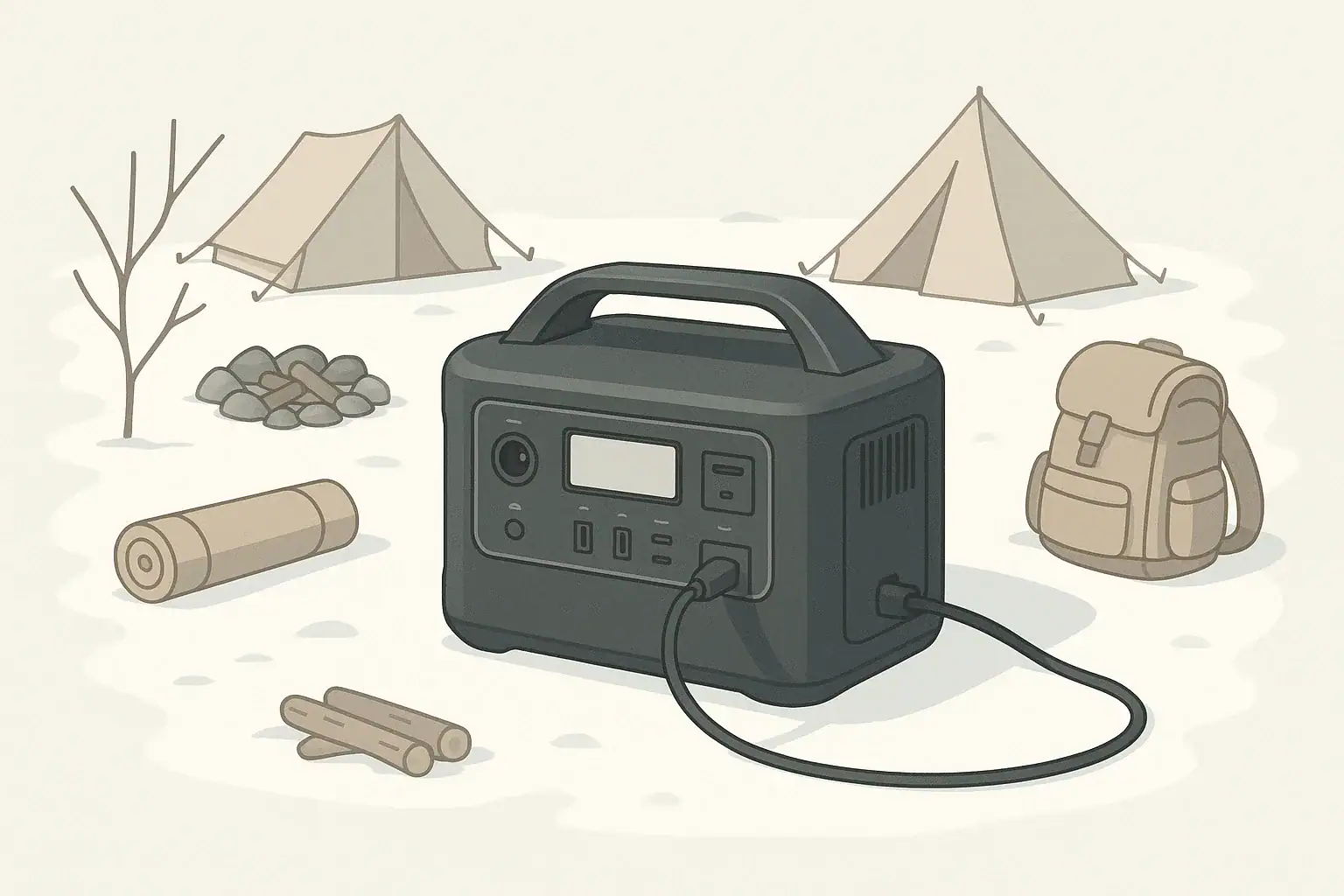
Portable power station at a snowy campsite in winter

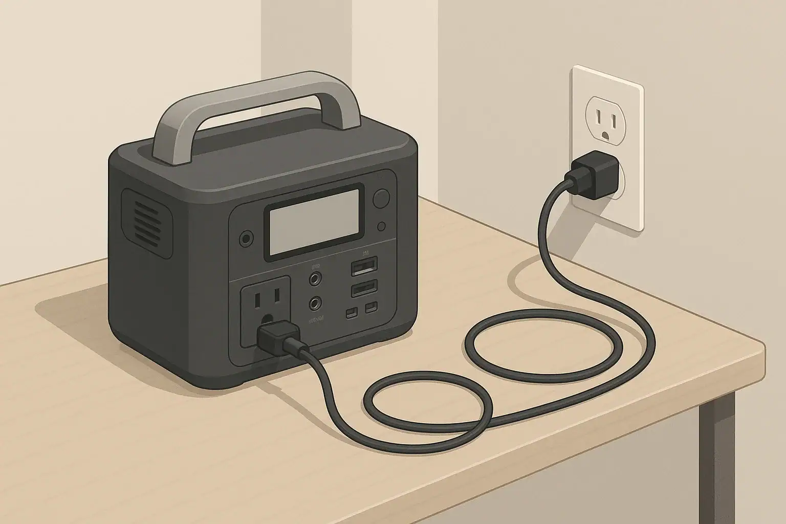
Charging a portable power station in freezing temperatures can permanently damage the battery, so you should warm the unit above its minimum charging temperature before plugging it in. Cold weather use is usually fine, but cold weather charging is where most of the risk lives.

When lithium batteries are charged below about 32°F (0°C), internal chemical reactions slow down and can cause lithium plating, capacity loss, and shorter battery life. You may still be able to discharge and run devices in the cold, but you need a different strategy for when and how you recharge.

This guide explains what happens inside a lithium battery in the cold, how much runtime you can realistically expect in winter, common cold‑weather mistakes, and practical steps to keep your portable power station safe, reliable, and ready for emergencies.

What “Charging in Freezing Temperatures” Really Means and Why It Matters

For portable power stations, “freezing” usually means around 32°F (0°C) and below, but the exact limits depend on the battery design. Many lithium batteries can discharge at temperatures well below freezing, yet their safe charging range is much narrower.

Manufacturers typically publish three separate temperature ranges:

  • Charging temperature – often something like 32–104°F (0–40°C).
  • Discharging temperature – often wider, for example 14–104°F (−10–40°C) or more.
  • Storage temperature – sometimes broader but still not intended for deep freeze long‑term.

Charging below the minimum charging temperature is where damage can occur. The pack may still “accept” charge if protections are weak or bypassed, but repeated cold charging can silently reduce capacity and increase internal resistance. Over time, that means shorter runtimes, more voltage sag, and a power station that feels much smaller than its original rating.

Understanding where these limits come from helps you plan winter camping trips, RV use, job‑site work, and home backup so that you charge warm, use cold, and keep the battery healthy for years.

How Cold Affects Lithium Batteries and Charging Behavior

Inside a lithium battery, energy moves as lithium ions travel through an electrolyte between the anode and cathode. Temperature changes the speed and efficiency of that movement.

In cold conditions:

  • Chemical reactions slow down – ions move more slowly, so the battery cannot accept or deliver current as easily.
  • Electrolyte becomes more viscous – the internal “liquid highway” gets thicker, raising internal resistance.
  • Voltage behavior changes – the same current causes more internal stress, and voltage drops faster under load.

These effects show up differently when you are discharging versus charging the battery.

Discharging in the Cold: Less Runtime, More Voltage Sag

When you run devices from a cold portable power station, you may notice:

  • Shorter runtimes than you get at room temperature.
  • Unexpected shutdowns under heavy loads, even when the display still shows remaining charge.
  • More frequent low‑battery or overload warnings.

This happens because the cold battery cannot deliver energy as efficiently. The inverter sees the battery voltage sagging and shuts down to protect the pack, even though some energy remains locked away until the cells warm back up.

Charging in the Cold: Lithium Plating and Permanent Damage

Charging in freezing conditions is more serious than simply losing runtime. At low temperatures, the anode cannot absorb lithium ions as quickly as the charger is trying to push them in. Instead of entering the anode structure, some lithium can deposit as metallic lithium on the surface. This is called lithium plating.

Over time, lithium plating can lead to:

  • Permanent capacity loss – part of the battery’s active material is no longer available for storing energy.
  • Higher internal resistance – the pack runs warmer under load and feels “weaker.”
  • Shortened lifespan – the battery reaches end of life sooner, even if it still appears to work.

Most modern power stations include a battery management system (BMS) that monitors temperature and will reduce or block charging when the pack is too cold. However, not all systems react the same way, and relying on protections alone is not a substitute for good habits.

Typical Temperature Ranges for Lithium Power Stations – Example values for illustration.
Use case Common temperature range What this means in practice
Charging 32–104°F (0–40°C) Aim to be comfortably above freezing before plugging in any charger.
Discharging (running devices) 14–104°F (−10–40°C) You can usually use the unit in light subfreezing conditions but expect less runtime.
Short‑term storage 14–95°F (−10–35°C) Okay for seasonal storage if you avoid deep freeze and high heat extremes.
Long‑term storage 41–77°F (5–25°C) Best range for long battery life when stored partially charged.

Because exact limits vary, treat your own product’s minimum charging temperature as a hard line and give yourself a safety margin above it.

Cold-Weather Examples: Camping, RV, Job Sites, and Home Backup

Understanding theory is helpful, but cold‑weather charging decisions are made in real situations: a tent at dawn, a frozen driveway, or a chilly workshop. These examples show how to apply the same principles in different scenarios.

Winter Camping and Vanlife

Imagine a weekend trip where overnight temperatures drop to 15°F (−9°C). Your power station spends the night in the tent vestibule powering a small fan and lights. In the morning you want to recharge from a folding solar panel.

  • The battery pack inside the unit is likely close to the outside air temperature.
  • The display may still show 40–50% remaining, but the internal cells are cold and sluggish.
  • Connecting solar right away may cause the BMS to refuse charging or accept only a trickle.

A better approach is to move the power station into the warmest part of the tent or vehicle, let it warm gradually while you make breakfast, and start charging once the interior has climbed above freezing.

RV and Remote Work Setups

In an RV or mobile office, the power station might live in a storage bay that drops below freezing overnight while you drive or park. The next morning you plug into shore power or start a generator and expect everything to charge as usual.

What actually happens:

  • The BMS may limit charge current until the pack warms, making “fast charging” much slower.
  • If sensors are not accurate or protections are minimal, the pack may accept high current while still too cold, increasing long‑term wear.
  • Voltage sag is more noticeable when running power tools or a coffee maker from a cold battery.

Planning to store the power station in the conditioned interior when hard freezes are expected, and opening cabinet doors around it while charging, can keep temperatures closer to the recommended range.

Cold Weather Home Backup and Short Outages

During a winter outage, you might grab a power station from an unheated garage where it has sat at 20°F (−6°C) for weeks. You bring it into the living room and immediately plug it into a small gasoline generator or wall outlet once power returns.

Safer practice looks like this:

  • Set the unit on a dry, stable surface away from heaters and stoves.
  • Allow it to slowly reach room temperature; wipe off any visible condensation.
  • Only then connect chargers and critical loads like lights, phones, or a modem.

Because cold reduces effective capacity, prioritize low‑wattage essentials instead of trying to run electric heaters or large appliances directly from the power station.

Outdoor Job Sites and Workshops

On a winter job site, it is common to leave a power station in the back of a truck overnight, then use it to run tools and charge batteries during the day. If you fast‑charge it from AC in an unheated workshop that is just above freezing, the cells are still cold even though the air feels “not that bad.”

In that situation, using a slower charging method or moving the unit into a slightly warmer space before fast charging can significantly reduce stress on the battery, especially if this pattern repeats all winter.

Common Cold-Weather Mistakes and Troubleshooting Cues

Most cold‑related battery problems come from a few repeatable mistakes. Recognizing them early can help you avoid permanent damage and troubleshoot odd behavior before it becomes serious.

Frequent Mistakes with Charging in Freezing Temperatures

  • Charging as soon as you come indoors – the outside of the case feels warmer than the internal cells, which may still be below freezing.
  • Leaving the unit on snow or concrete – it stays colder longer than you expect, especially in light wind.
  • Using the fastest charger in marginal temperatures – high current at just‑above‑freezing conditions increases stress on the cells.
  • Assuming the display temperature equals cell temperature – some sensors read air or case temperature, not the battery core.
  • Ignoring repeated charge throttling or error codes – the BMS may be warning you that the pack is too cold.

Cold exposure and improper charging do not always cause immediate failure. Look for patterns over time:

  • Noticeably shorter runtimes than when the unit was new, even at moderate temperatures.
  • More frequent low‑battery shutdowns under loads that used to be fine.
  • Longer charging times for the same input power.
  • Intermittent or new error messages when charging after cold storage.

These issues can have other causes, but if they show up after a season of winter use, cold charging is a likely contributor.

Cold-Weather Issues and What to Do Next – Example values for illustration.
Observed issue Likely cause Immediate action Longer‑term step
Unit will not start charging after a night in the car BMS blocking charge due to low temperature Bring indoors, let it warm to room temperature, then retry. Store above freezing when hard freezes are expected.
Fast shutdown when running a space heater in the cold Voltage sag and inverter overload Turn off the heater and switch to low‑wattage loads. Avoid running high‑draw heaters from small power stations.
Runtime much shorter than in summer Reduced effective capacity at low temperature Move the unit to a less exposed, insulated spot. Plan extra capacity for winter trips and outages.
Condensation on case after bringing it indoors Moisture from warm air hitting cold surfaces Let it dry fully before charging or heavy use. Use bags or covers to reduce moisture swings.
New clicking sounds or unusual smell while charging Possible internal fault or damage Stop charging immediately and power down. Contact the manufacturer or a qualified service provider.

When to Stop and Seek Help

If you notice swelling of the case, a sweet or chemical odor, visible damage, or repeated error codes that do not clear after warming and restarting the unit, stop using it. Do not attempt to open the enclosure or bypass safety systems. Contact the manufacturer or a qualified technician for guidance on inspection, repair, or recycling.

Cold-Weather Safety Basics for Portable Power Stations

Cold temperatures add extra stress to the battery, but most safety issues arise when cold is combined with moisture, poor ventilation, or improvised electrical connections. A few high‑level rules go a long way.

Temperature and Placement Safety

  • Avoid extreme swings – do not move the unit directly from deep freeze to high heat, such as next to a heater or stove.
  • Keep vents clear – even in winter, the inverter and BMS need airflow to shed heat while charging or under heavy load.
  • Elevate off snow and standing water – use a board, crate, or dry mat to reduce moisture exposure and shock risk.

Electrical and Load Safety

  • Use appropriate cords – cold makes many cables stiff and more prone to cracking; inspect insulation before use.
  • Avoid overloading – cold batteries sag more under load, so devices that were “borderline” in summer may now trip overload protection.
  • Do not backfeed building wiring – never connect a portable power station to household circuits without proper transfer equipment installed by a professional.

Ventilation and Indoor Use

  • Ensure adequate airflow – do not bury the unit under blankets or clothing to “keep it warm.”
  • Respect other heat sources – maintain clearance from gas heaters, fireplaces, and cooking appliances.
  • Follow device instructions – some connected loads, such as medical equipment, have their own temperature and ventilation requirements.

Most modern portable power stations include multiple layers of protection, but those systems are designed to work within published limits. Using the unit within its specified temperature range and avoiding improvised electrical setups is the foundation of safe cold‑weather operation.

Long-Term Cold-Weather Care, Storage, and Battery Health

How you store and maintain a portable power station between trips or seasons matters just as much as how you use it on any given winter day. Good habits can preserve capacity and reduce unpleasant surprises when you need backup power most.

Off-Season Storage in Cold Climates

  • Choose a moderate location – a closet, interior room, or conditioned basement is better than an unheated shed or vehicle.
  • Avoid full charge or full empty – many lithium batteries age best when stored around 30–60% state of charge.
  • Top up periodically – check and recharge every few months to prevent deep discharge from self‑drain.

If your only option is a space that occasionally dips below freezing, keep the unit off bare concrete and away from exterior walls. An insulated shelf or cabinet can reduce temperature swings and moisture exposure.

Post-Winter Inspection

After a season of cold use, a quick inspection can catch issues before they become failures:

  • Look for cracks in the housing, loose handles, or damaged feet from impacts in cold weather.
  • Inspect AC outlets and DC ports for corrosion, dirt, or moisture staining.
  • Check cords and adapters for stiff spots, nicks, or cracked insulation.

If any damage is found, retire the affected cords or accessories and follow the manufacturer’s guidance for the power station itself.

Planning Capacity for Winter Use

Because cold reduces effective capacity, it is reasonable to assume that real‑world winter runtimes may be noticeably lower than the nameplate watt‑hour rating suggests. Many users plan with a margin, such as treating a 1,000 Wh unit as if it were only 700–800 Wh in freezing conditions, depending on load type and exposure time.

That extra buffer can be the difference between running only essentials through a long winter night versus unexpectedly running out of power before morning.

Practical Takeaways and Specs to Look For

Cold weather does not mean you cannot rely on a portable power station. It does mean you need to think about when you charge, where you store the unit, and which specifications matter most for winter use.

Key Takeaways for Charging in Freezing Temperatures

  • Use your power station in the cold if needed, but avoid charging below the stated minimum temperature.
  • Warm the unit gradually to above freezing before plugging in any charger, whether AC, solar, or vehicle.
  • Expect shorter runtimes and more voltage sag in winter; plan extra capacity or reduce loads.
  • Store the unit in a cool, dry place that generally stays above freezing and avoid leaving it fully charged or fully empty for long periods.
  • Watch for warning signs like new error codes, unusual smells, or rapid capacity loss after cold exposure.

Specs to Look For When You Expect Cold-Weather Use

When comparing portable power stations for use in freezing climates, the spec sheet can tell you a lot about how they will behave in winter. Pay particular attention to:

  • Minimum charging temperature – the lower this value (within reason), the more flexible the unit is for cold‑weather charging.
  • Discharge temperature range – a wider range supports more reliable operation on cold nights.
  • Storage temperature range – important if the unit will live in a garage, RV, or cabin.
  • Battery chemistry – different lithium chemistries (for example, LiFePO4 versus other lithium‑ion types) have different cold‑weather behavior and cycle life characteristics.
  • BMS protections – look for explicit mention of low‑temperature charge protection, thermal sensors, and automatic charge throttling.
  • Available charge inputs – multiple input options (AC, DC, solar) let you choose slower or gentler charging methods in marginal conditions.
  • Usable capacity at low temperature (if stated) – some manufacturers provide performance graphs showing capacity versus temperature.

Matching these specifications to your climate and use case helps ensure that your power station remains dependable in winter, without relying on risky cold‑weather charging habits that shorten battery life.

Frequently asked questions

Which specifications and features most affect a power station’s performance when charging in freezing temperatures?

Minimum charging temperature, discharge and storage temperature ranges, and battery chemistry are the most important specs. Also look for explicit BMS low‑temperature protections, thermal sensors, and information about usable capacity at low temperatures. Multiple input options (AC, DC, solar) let you choose gentler charging methods in marginal conditions.

Can I charge a power station immediately after bringing it inside from the cold?

No — you should let the unit warm gradually above the minimum charging temperature before charging. Charging while the internal cells are still cold risks lithium plating and long‑term capacity loss, and the BMS may refuse to charge until the pack warms.

What immediate safety steps should I take if I suspect cold-related battery damage?

Stop charging and disconnect any loads, then move the unit to a well‑ventilated, moderate‑temperature area and avoid rapid heating. Do not open the enclosure or attempt repairs; contact the manufacturer or a qualified technician for inspection and disposal guidance if you see swelling, strong odors, or persistent error codes.

How much runtime loss is typical when using a power station in very cold conditions?

Runtime reduction varies with temperature, load, and exposure time, but many users see noticeably lower effective capacity — often on the order of 20–30% or more under severe cold. Plan additional capacity or reduce loads for winter use to avoid unexpected outages.

Are there safer ways to charge with solar or vehicle charging when temperatures are near freezing?

Yes — use lower charge currents or slower charge modes and, when possible, move the station into a warmer space before charging. Insulating the unit from wind and placing it in a sheltered, dry enclosure can help, but the best practice is to ensure internal cell temperature is above the manufacturer’s minimum before applying significant charge current.

How can I reduce condensation risk when bringing a cold power station indoors?

Bring the unit into a cool, dry room and let it warm gradually in a sealed bag or case to limit moisture contact, then open and dry any visible condensation before charging. Avoid placing it directly next to heaters or humid environments to prevent rapid temperature swings that create condensation.

Cold-Weather Capacity Loss: How Much Power You Really Lose

portable power station in a snowy campsite winter scene

Portable power stations typically lose about 10–30% of their usable capacity around freezing and up to 40–50% in very cold weather, even when fully charged. This cold weather capacity loss is normal behavior for lithium batteries, not usually a defect, but it can dramatically shorten the runtime you get for winter power outages, camping, or vanlife.

Understanding how low temperatures affect battery performance helps you plan realistic runtimes, avoid sudden shutdowns, and protect your investment. Instead of relying only on the rated watt-hours printed on the label, you can adjust for cold, load, and age to get a much closer estimate of what your portable power station will actually deliver.

This guide explains why batteries lose capacity in the cold, shows real-world examples, walks through common mistakes and troubleshooting cues, and finishes with safety basics, storage tips, and a practical specs checklist to use before your next winter trip or storm.

What Cold-Weather Capacity Loss Means and Why It Matters

Cold-weather capacity loss is the drop in usable energy you get from a portable power station when the battery is cold compared with its rated capacity at room temperature. The label might say 1,000 Wh, but in freezing temperatures you may only be able to use 600–800 Wh before the unit shuts down.

This matters because most people size their portable power station based on ideal conditions. In winter, that same setup can fall short for critical loads such as communication devices, medical equipment, or heating accessories. Knowing how much capacity you really lose lets you plan a margin of safety instead of being surprised by early cutoff.

Cold capacity loss is usually temporary and mostly reversible: when the battery warms back up, much of the apparent “missing” energy becomes usable again. However, repeatedly operating or charging at extreme low temperatures can contribute to long-term wear and permanent capacity loss over the life of the pack.

In practical terms, cold weather capacity loss affects:

  • How long your lights, router, or fridge will run during a winter outage
  • Whether your laptop and hotspot last through a remote workday in a cold cabin
  • How much backup you need for overnight camping when temperatures drop below freezing

How Cold Affects Battery Chemistry and Performance

Portable power stations typically use lithium-based batteries. These cells are designed and rated around room temperature, often about 68–77°F (20–25°C). As temperature drops, the internal chemistry slows and resistance increases, which changes how the battery behaves under load and during charging.

Slower Chemical Reactions and Higher Internal Resistance

Inside each cell, lithium ions move between electrodes through an electrolyte. Cold temperatures slow this movement and increase internal resistance. The result is:

  • Lower effective capacity under load: the pack cannot deliver as much energy before voltage drops to cutoff.
  • Reduced peak power capability: the battery struggles more with sudden or heavy loads.
  • More heat from internal losses: some energy is lost as heat instead of going to your devices.

Manufacturers rate capacity at a specific temperature and discharge rate. When you move away from those conditions—especially toward freezing or below—the real-world watt-hours you can draw decrease.

Voltage Sag and Early Shutoff

battery management system inside a power station constantly monitors voltage and temperature to keep operation within safe limits. In the cold, voltage under load sags more quickly. If voltage dips below a preset threshold, the system shuts output off to protect the cells, even if there is still some energy remaining.

This is why you might see a state-of-charge display that still shows 15–25%, but the unit suddenly turns off when you plug in a heavier device, especially in cold conditions. The cold exaggerates this effect, and high loads make it worse.

Cold Charging Limitations

Charging lithium batteries when they are very cold can cause internal damage, such as metallic lithium plating on the anode. To prevent this, most power stations:

  • Reduce charge current at low temperatures
  • Block charging entirely below a defined cutoff
  • Display warnings or error codes when the pack is too cold

These behaviors are protective features, not faults. If your unit will not charge after being in a cold car or shed, it usually needs time to warm up internally before normal charging resumes.

Typical Capacity Loss by Temperature

The exact numbers vary by battery chemistry, pack design, and load, but many users see patterns like these under light-to-moderate loads:

  • Around 50°F (10°C): small, often barely noticeable loss
  • Around 32°F (0°C): roughly 10–30% less usable capacity
  • Well below freezing: 30–50% or more loss, especially under higher loads

These effects stack on top of normal inefficiencies such as inverter losses, so the difference between the rated watt-hours and what you get in real winter use can be large.

Approximate cold-weather capacity vs. temperature – how much usable energy you may see compared with the rated watt-hours at room temperature. Example values for illustration.
Battery temperature Approx. usable capacity vs. rating What you might notice in use
77°F (25°C) 90–100% Performance close to spec sheet; minor losses only.
50°F (10°C) 85–95% Most users see little difference for light loads.
32°F (0°C) 70–90% Noticeable runtime reduction, especially with laptops or fridges.
14°F (-10°C) 50–70% Shorter runtimes; more early shutdowns with high-wattage devices.
-4°F (-20°C) 40–60% Hard to power heavy loads; frequent low-voltage cutoff.

Real-World Cold-Weather Runtime Examples

To make cold weather capacity loss more concrete, it helps to walk through specific scenarios. These examples assume a 1,000 Wh portable power station rated at room temperature and used after it has cooled to around freezing.

Example 1: Winter Power Outage With Home Essentials

Imagine a 1,000 Wh unit powering:

  • Wi-Fi router and modem: 20 W total
  • LED lamp: 10 W
  • Phone charging: 10 W average over time

Total load is about 40 W. At room temperature and assuming 85% overall efficiency, you might expect roughly:

  • 1,000 Wh × 0.85 ÷ 40 W ≈ 21 hours of runtime

At freezing, if usable capacity drops to about 80% of rated, the effective energy is closer to 800 Wh × 0.85 ≈ 680 Wh. That gives:

  • 680 Wh ÷ 40 W ≈ 17 hours of runtime

The difference—about 4 hours—can matter if you are planning for an overnight outage.

Example 2: Cold-Weather Camping With a Laptop and 12 V Fridge

Consider the same 1,000 Wh station used in a camper at 28°F (-2°C) to power:

  • Laptop for remote work: 60 W while in use
  • 12 V compressor fridge: 45 W while running, 30% duty cycle
  • Interior LED lights: 10 W

The average load is roughly:

  • Laptop: 60 W for 8 hours ≈ 480 Wh
  • Fridge: 45 W × 0.3 ≈ 14 W average over 24 hours
  • Lights: 10 W for 6 hours ≈ 60 Wh

With cold-related loss to around 70–80% usable capacity and normal inefficiencies, you might only have about 650–750 Wh realistically available. That means a full 24-hour day of work, cooling, and lighting may nearly drain the battery, whereas the same setup in mild weather would have more margin.

Example 3: High-Wattage Loads in the Cold

High loads exaggerate cold weather capacity loss. If you try to run a 500 W space heater from a 1,000 Wh station at 20°F (-7°C), the unit may:

  • Shut down early due to voltage sag
  • Deliver far less than the expected 1–2 hours of runtime
  • Run its fans hard while still not keeping up with the heating need

Even if the battery technically has enough watt-hours, the combination of cold, high current, and inverter losses can make the heater impractical. In most winter scenarios, prioritizing lower-wattage loads (insulation, sleeping bags, efficient clothing, and small electronics) is far more efficient than trying to heat air with battery power.

Cold-weather runtime planning examples – typical device loads and how cold capacity loss changes expectations. Example values for illustration.
Use case Approx. load (W) Room-temp runtime on 1,000 Wh Freezing runtime on 1,000 Wh
Router + lamp + phones 40 W ~20–22 hours ~15–18 hours
Laptop + lights 80 W ~10–11 hours ~7–9 hours
12 V fridge (average) 30–40 W ~22–28 hours ~16–22 hours
Small power tool use (intermittent) 150–300 W bursts Several hours of mixed use Noticeably fewer cuts/drills per charge
Compact space heater 400–600 W ~1–2 hours Often under 1 hour before cutoff

Common Cold-Weather Mistakes and Troubleshooting Cues

Most winter problems with portable power stations come from a few predictable mistakes. Recognizing the signs helps you decide whether you are seeing normal cold weather behavior or a true fault.

Mistake 1: Assuming Rated Capacity in Any Weather

Many users plan runtimes by dividing rated watt-hours by load watts without adjusting for temperature or inverter losses. In cold weather this leads to:

  • Unexpectedly short runtimes
  • Critical devices shutting off overnight
  • Misjudging how many days of power a setup can provide

Troubleshooting cue: If your math says you should get 10 hours but you only see 6–7 in freezing conditions, that gap is often normal cold weather capacity loss plus efficiency overhead, not necessarily a defective battery.

Mistake 2: Leaving the Unit Cold-Soaked Before Use

Storing the power station in an unheated garage, vehicle trunk, or shed and then using it immediately in a cold environment means the internal cells start the day cold. The pack may warm slightly under load, but initial capacity and power delivery will be reduced.

Troubleshooting cue: If you move the unit into a warmer space for a few hours and runtimes improve, the issue was temperature, not a failing pack.

Mistake 3: Charging When the Battery Is Very Cold

Trying to fast-charge a cold battery is one of the easiest ways to shorten its life. Some units will refuse to charge or limit input power; others may charge but at the cost of long-term capacity.

Troubleshooting cue: If charging is very slow or blocked and the display shows a low-temperature warning, bring the station indoors, let it sit unplugged until the case feels close to room temperature, then try again.

Mistake 4: Running High-Wattage Devices Continuously

Space heaters, hair dryers, kettles, and large power tools draw a lot of current. In the cold, this triggers stronger voltage sag and earlier protective shutdown.

Troubleshooting cue: If the station shuts off quickly with a heavy appliance but runs fine with lighter loads, the behavior is usually normal. Reduce load, use lower power settings, or run heavy devices for shorter bursts.

Mistake 5: Blocking Vents With Insulation

Insulating the unit to keep it warm is helpful, but covering vents or fans can cause overheating or derating, especially when the inverter is working hard.

Troubleshooting cue: If the unit runs hot, throttles output, or shows over-temperature warnings even in cold air, check that vents are completely unobstructed and that there is some airflow around the case.

Cold-Weather Safety Basics for Portable Power Stations

Cold weather does not remove electrical or battery risks. It simply changes which issues are most likely. A few high-level safety habits go a long way.

Temperature and Placement

  • Operate the power station within the manufacturer’s recommended temperature range whenever possible.
  • Avoid leaving the unit for long periods in locations that regularly drop well below freezing.
  • Keep the station on a dry, stable surface away from snow, ice melt, and standing water.

Ventilation and Enclosures

  • Do not fully enclose the power station in blankets, boxes, or bags that block fans or vents.
  • If you use an insulated cover, ensure there are clear openings for air intake and exhaust.
  • Leave space around the unit so warm air from the inverter and charger can escape.

Extension Cords and Loads

  • Use cords and power strips rated for the wattage you plan to draw.
  • Route cables to avoid trip hazards on snow or ice, and keep connectors off wet ground.
  • Avoid daisy-chaining multiple strips or adapters, especially with high-wattage devices.

Home Backup Considerations

  • Do not attempt to backfeed a home electrical panel with improvised connections.
  • Use dedicated, clearly labeled outlets on the power station to run individual appliances.
  • If you plan to integrate with home circuits via a transfer switch, consult a qualified electrician.

Maintenance and Storage for Winter and Long-Term Use

maintenance and storage habits reduce both temporary cold weather capacity loss and permanent long-term degradation.

Short-Term Winter Handling

  • Before a storm or trip, charge the station indoors to the recommended level.
  • Keep the unit in a heated area until shortly before use, then move it to the colder environment.
  • When possible, operate the station in a tent vestibule, vehicle cabin, or insulated compartment rather than fully exposed to the cold.

Off-Season and Between-Trip Storage

  • Store the power station in a cool, dry place—not in direct sun, not next to heaters, and not in damp basements.
  • Avoid long-term storage at 0% or 100% state of charge; a moderate charge level is often best for longevity.
  • In very cold climates, avoid leaving the unit in unheated sheds or vehicles for months at a time.

Periodic Checks and Top-Ups

  • Check the state of charge every few months during storage and top up if it has dropped significantly.
  • Exercise the battery occasionally by running a moderate load and then recharging within the recommended temperature range.
  • Inspect cables, ports, and the case for damage before winter season use.

Signs of Long-Term Degradation vs. Normal Cold Behavior

It is important to distinguish between normal cold weather performance and signs that the battery itself is aging or damaged.

  • Likely normal cold behavior: runtimes improve noticeably when used in warmer conditions; charging resumes after warming up; shutdowns mainly occur with high loads in the cold.
  • Possible long-term degradation: significantly reduced runtime even at room temperature; rapid drop from high to low state-of-charge; noticeable swelling, unusual noises, or persistent error codes.

If you observe symptoms that persist in mild temperatures, the issue is more likely wear, damage, or another fault rather than simple cold weather capacity loss.

Practical Takeaways and Specs to Look For

Cold weather does not have to make your portable power station unreliable. With realistic expectations, a bit of planning, and the right specs, you can get predictable winter runtimes and preserve long-term battery health.

Key Planning Takeaways

  • Expect 10–30% capacity loss around freezing and more at very low temperatures.
  • Use conservative runtime estimates that include both cold effects and inverter losses.
  • Prioritize low- and moderate-wattage devices over continuous high-wattage loads.
  • Keep the battery as close to room temperature as practical before and during use.
  • Avoid charging when the pack is very cold; let it warm up first.

Specs to Look For on a Cold-Weather-Friendly Power Station

When comparing portable power stations with winter use in mind, pay attention to more than just watt-hours and peak watts. The following specs and features help determine how well a unit will handle cold weather capacity loss:

  • Operating temperature range: especially minimum discharge and charge temperatures.
  • Battery chemistry: some chemistries handle cold better than others, though all lithium types lose capacity in low temperatures.
  • Battery management system protections: clear low-temperature charging and discharging safeguards.
  • Display and monitoring: temperature indicators, error codes, and accurate state-of-charge readings.
  • Inverter efficiency: higher efficiency means less wasted energy, which matters more when cold already reduces capacity.
  • Continuous vs. surge power ratings: realistic continuous output for the devices you plan to run in winter.
  • Pass-through charging behavior: how the unit behaves when powering devices while being charged in cold conditions.
  • Physical design: handles, size, and shape that make it easy to keep indoors or in insulated compartments.

By combining these specs with the planning ideas in this guide, you can better match a portable power station to your winter use cases and avoid being caught off guard by cold weather capacity loss when you need reliable backup the most.

Frequently asked questions

Which battery specs should I prioritize for winter use?

Look for a documented operating temperature range (minimum discharge and charge temps), a robust battery management system with low-temperature protections, and a high inverter efficiency rating. Also consider the unit’s continuous output rating and any thermal management features that help the pack retain or shed heat safely.

Is charging a cold battery safe, and what should I do instead?

Charging a very cold lithium battery can cause internal damage such as lithium plating, so many units will limit or block charging until they warm. If your station won’t accept full charge, move it to a warmer location or let it warm up naturally before charging to protect long-term capacity.

What safety precautions should I take when using a portable power station in cold weather?

Operate the unit within the manufacturer’s temperature and ventilation guidelines, keep it dry and elevated off wet ground, and use properly rated cords and outlets. Avoid improvised connections to home panels and ensure vents aren’t blocked by insulation or snow.

How much runtime reduction should I expect at freezing temperatures?

Many users see roughly 10–30% less usable capacity around 32°F (0°C), with larger losses below freezing—often 30–50% under heavier loads. Exact reduction depends on battery chemistry, load size, age of the pack, and the unit’s thermal design.

Can insulating the unit improve cold performance?

Insulation can help the pack retain heat and reduce short-term capacity loss, but it must not block vents or fans. Use an insulated enclosure that allows airflow and monitor the unit during high loads to avoid overheating or inverter derating.

How can I minimize long-term capacity loss from winter use?

Avoid charging when the battery is very cold, store the unit at a moderate state of charge in a temperate location, and limit repeated deep cycling at extreme temperatures. Warming the pack before charging and doing occasional exercise cycles in recommended temperature ranges also helps preserve capacity.

Extension Cords and Power Strips: Safe Practices With Portable Power Stations

Portable power station on table with neatly managed cords

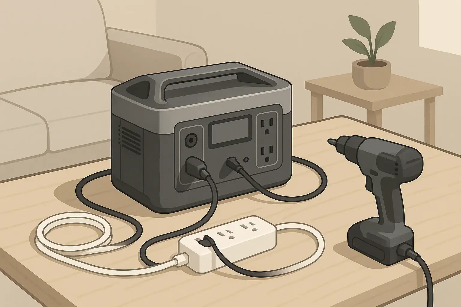
You can safely use extension cords and power strips with portable power stations as long as the total load stays within the ratings of the station, the cord, and the strip, and nothing overheats. The goal is to extend reach and add outlets without creating hidden overloads, voltage drop, or fire hazards.

This refreshed guide explains safe extension cord use with portable power stations for home, office, vehicle, and camping setups. It covers how to size cords, plan loads, spot trouble, and choose power strips that match your inverter output. The focus is on practical, real-world scenarios using the built-in AC outlets on your power station, not on any permanent wiring or DIY electrical work.

If you want reliable backup power or off-grid convenience, treating cords and strips as part of the system—not as afterthoughts—will keep your portable power station running safely and efficiently.

Why Extension Cords and Power Strips Matter With Portable Power Stations

Portable power stations concentrate a lot of capability into a small box, but their built-in AC outlets are usually in one place. Extension cords and power strips let you move that power to where you actually need it: a workbench, a tent, a home office corner, or the far side of a living room.

Every extra cord, connector, and outlet adds resistance and potential failure points. If you ignore ratings or placement, you can end up with:

  • Tripped overload protection on the power station
  • Voltage drop that makes devices behave unpredictably
  • Overheated cords, plugs, or power strips
  • In extreme cases, risk of fire or electric shock

Used correctly, though, extension cords and power strips are powerful tools. They let you:

  • Keep the power station in a cool, ventilated, safe location
  • Distribute power to multiple small devices from a single outlet
  • Organize cables in a predictable way during outages or camping trips

Thinking about cords and strips as part of your power plan, rather than last-minute add-ons, is the first step toward safe, repeatable setups.

Key Concepts: Ratings, Loads, and How Everything Works Together

Safe use starts with understanding how the power station, extension cords, and power strips interact.

Know Your Power Station Limits

  • Battery capacity (Wh): Determines how long you can run devices. It does not change how many watts you can draw at once.
  • Inverter continuous power (W): The maximum steady AC output. All devices on all AC outlets, cords, and strips combined must stay under this.
  • Inverter surge power (W): Short bursts above the continuous rating to start motors or compressors.
  • Outlet ratings (A): Individual AC outlets may have their own amp limits, which can be lower than the inverter’s total rating.

Add up the running watts of everything you plan to plug in at the same time. Stay comfortably below the continuous watt rating of the power station, especially if any device has a motor or heating element.

Extension Cords vs. Power Strips

  • Extension cord: Extends reach. Its main safety factors are wire gauge, length, and jacket rating (indoor vs. outdoor).
  • Power strip: Adds outlets. It often includes a short cord, an on/off switch, sometimes surge protection, and a clearly marked amp or watt rating.

You can plug a power strip into a portable power station directly or into a single heavy-duty extension cord. Each added piece should be at least as robust as the load it carries. It is safer to use one appropriately rated strip on a heavy-duty cord than to build chains of light-duty strips and cords.

Amps, Watts, and Wire Gauge

  • Watts (W): Power. On 120 V systems, watts ≈ volts × amps.
  • Amps (A): Current. Cords and strips are usually rated in amps.
  • Wire gauge (AWG): Thickness of the copper conductors. Smaller numbers mean thicker wire (12 AWG is thicker than 16 AWG).

Thicker, shorter cords run cooler and waste less energy. Thinner, longer cords run hotter and drop more voltage. For higher loads or longer distances, choose a lower AWG number and avoid unnecessary length.

Choosing Extension Cord Gauge and Length for Portable Power Stations Example values for illustration.
Approx. Total Load on Cord Typical Use Case Suggested Minimum Gauge (up to ~25 ft) Suggested Minimum Gauge (25–50 ft)
Up to 150 W (≈1.3 A) Phone chargers, LED lamps, small speakers 16 AWG light-duty 16 AWG light-duty
150–500 W (≈1.3–4.2 A) Laptop, monitor, fan, router 16 AWG or 14 AWG 14 AWG
500–1000 W (≈4.2–8.3 A) Mini fridge, small power tools, small microwave 14 AWG 12 AWG
1000–1500 W (≈8.3–12.5 A) Space heater, hot plate, large kettle 12 AWG heavy-duty 12 AWG heavy-duty (shorter is strongly preferred)

Real-World Setups and Load Planning Examples

Seeing how extension cords and power strips work in actual setups makes the ratings easier to apply. The examples below assume a 120 V portable power station.

Example 1: Home Office During a Power Outage

You place the power station in a hallway where it is cool and out of the way, then run one 25 ft 14 AWG extension cord to your desk, ending in a power strip.

  • Laptop: 90 W charger
  • Monitor: 40 W
  • Desk lamp (LED): 10 W
  • Wi-Fi router: 15 W

Total load: about 155 W. This is well within the rating of most power strips and extension cords, and far below the continuous output of many portable power stations. The strip gives you enough outlets to keep the desk organized, and the cord lets you keep the power station away from your feet.

Example 2: Camping With a Small Fridge and Lighting

The power station sits under a canopy, protected from direct sun and rain. You run one outdoor-rated 12 or 14 AWG cord to a small power strip at a camp table.

  • Mini fridge: 70 W running, 200–300 W surge
  • Two LED lanterns with AC adapters: 10 W each
  • Occasional phone charger: 10–20 W (could also use the station’s USB ports)

Running load is around 100–110 W, but you plan for the fridge’s starting surge. You avoid plugging other motor loads (like an air pump) into the same strip so that the fridge can start reliably without nuisance shutdowns.

Example 3: High-Draw Appliance on a Dedicated Cord

You want to run a 1200 W electric kettle from a mid-sized power station. Instead of sharing a strip, you plug a short, heavy-duty 12 AWG extension cord directly into the power station and plug the kettle into that cord alone.

  • Total load: about 1200 W
  • Cord is short and thick, minimizing voltage drop and heat
  • No other devices on the same cord or strip

This approach keeps the high current off your lighter-duty cords and strips. You also verify that 1200 W is within the station’s continuous rating before you start.

Example Loads and Common Planning Decisions With Portable Power Stations Example values for illustration.
Device or Setup Approx. Total Watts Better Cord/Strip Strategy
Two laptops + monitor + lamp 180–250 W One quality power strip on a 14–16 AWG cord
Mini fridge + fan 120–200 W running Single strip on 14 AWG cord; avoid other motor loads
Space heater on high 1200–1500 W Dedicated short 12 AWG cord, no strip, no other loads
Phone and tablet charging only 20–60 W Use power station USB ports; minimal or no AC cords needed

Common Mistakes and Troubleshooting Cues

Most problems with extension cords and power strips on portable power stations come from the same few habits. Recognizing them early helps you fix issues before they become serious.

Overloading Cords or Strips

Symptoms:

  • Cord or strip feels hot to the touch (not just slightly warm)
  • Plastic around plugs looks discolored or soft
  • Strip’s reset button or breaker trips repeatedly

What to do:

  • Reduce the number of high-watt devices on that cord or strip
  • Upgrade to a heavier-gauge cord or higher-rated strip
  • Use a dedicated cord for any single device over about 1000 W

Daisy-Chaining Strips and Cords

Plugging one power strip into another, or building long chains of cords, makes it hard to see where the real limit is.

Risks:

  • Hidden overload on the first strip in the chain
  • Loose connections that heat up under load
  • Difficulty tracing which device is causing trips or shutdowns

Better approach: Use a single, appropriately rated strip at the far end of one heavy-duty extension cord. If you need more reach, move the power station or use a single longer heavy-duty cord instead of multiple cords joined together.

Ignoring Starting Surges

Devices with motors and compressors (fridges, some pumps, some tools) draw a short surge when they start. If several start at once on the same strip, they can trip the power station’s protection even if the running watts look safe.

Warning signs include:

  • Power station shuts down when the fridge or pump cycles on
  • Strip or cord clicks off briefly when a motor starts

Fixes:

  • Move motor loads to their own strip or cord
  • Start motors one at a time instead of all together
  • Leave extra headroom below the inverter’s continuous rating

Using Damaged or Inappropriate Cords

Old cords with cracked insulation, bent blades, or loose outlets are weak links in an otherwise safe setup.

  • Do not tape over damaged spots; replace the cord.
  • Avoid indoor-only cords in damp or outdoor areas.
  • Avoid adapters that defeat the grounding pin on three-prong plugs.

If you notice buzzing, sparking, or a burning smell from any connection, unplug immediately and retire the suspect cord or strip.

High-Level Safety Basics for Cords, Strips, and Portable Power Stations

A few high-level rules dramatically reduce risk when combining portable power stations with extension cords and power strips.

Stay Within the Lowest Rating in the Chain

The safe limit is always set by the weakest component:

  • If the power station can supply 1800 W but your strip is rated for 1200 W, treat 1200 W as your ceiling on that strip.
  • If a cord is rated for 10 A (about 1200 W at 120 V), do not exceed that load even if the station and strip are rated higher.

Check the printed labels on the power station, strip, and cord, and plan for the lowest number.

Use Grounded, Appropriately Rated Equipment

  • Prefer three-prong grounded cords and strips when your power station offers grounded outlets.
  • Match indoor or outdoor ratings to the environment you are using.
  • Use cords and strips that include built-in overload protection where possible.

Keep Everything Cool and Dry

  • Place the power station on a stable, level surface with several inches of clearance around vents.
  • Avoid coiling cords tightly while in use; lay them out loosely to dissipate heat.
  • Keep cords and strips out of puddles, off wet ground, and away from standing water.

Do Not Backfeed or Modify House Wiring

Portable power stations are not designed to energize household wiring through a wall outlet. Avoid any setup that involves feeding power into a home circuit or panel without proper, code-compliant equipment installed by a qualified professional.

Maintenance, Storage, and Long-Term Use

Extension cords and power strips are consumable items. Treating them as part of your portable power system and maintaining them over time improves safety and reliability.

Routine Inspection Habits

  • Before each use: Check for cuts, nicks, crushed sections, or exposed copper. Flex the cord lightly near the plugs to see if the jacket is splitting.
  • After heavy loads: Once you unplug, feel the cord and strip. If any section is noticeably hot, reconsider your load or upgrade the cord.
  • Annually: Retire cords or strips that are stiff, brittle, or discolored, even if they still work.

Storage Best Practices

  • Coil cords loosely in large loops to avoid kinks and internal conductor damage.
  • Store cords and strips in a dry, cool place away from direct sunlight and chemicals.
  • Separate outdoor cords from indoor cords so you do not mix them up during quick setups.

Planning for Repeated Use

If you regularly use a portable power station for the same task (such as a weekly outdoor workbench or recurring campsite), consider building a repeatable kit:

  • Label cords with their gauge and typical use (for example, “12 AWG – heater/fridge” or “16 AWG – lights/chargers”).
  • Bundle each setup (office, camping, emergency) with its own cords and strip so you are not guessing under time pressure.
  • Keep a small notepad or label on the power station listing typical loads and safe combinations you have already tested.

Practical Takeaways and Specs to Look For

Safe extension cord use with portable power stations comes down to matching ratings, minimizing heat, and keeping setups simple and visible.

Key Takeaways

  • Treat the entire chain (power station, cord, strip, devices) as one system and respect the lowest rating.
  • Use thicker, shorter cords for higher loads and longer runs; avoid unnecessary length and daisy-chains.
  • Group low-power devices on shared strips, but give high-draw appliances their own dedicated cords.
  • Watch for heat, smells, discoloration, or frequent tripping as early signs that something is undersized or failing.
  • Plan repeatable setups for your most common use cases so you are not improvising under stress.

Specs to Look For When Buying Cords and Power Strips

When you shop for gear to pair with a portable power station, these specifications matter most:

  • Wire gauge (AWG): Prefer 14 AWG or 12 AWG for higher loads and longer runs; 16 AWG is usually fine for light-duty use.
  • Amp rating: Look for clear amp and watt ratings on strips and cords; match them to your typical loads with extra headroom.
  • Grounding: Three-prong grounded plugs and outlets for grounded devices.
  • Indoor/outdoor rating: Outdoor-rated jackets for camping, garages, or any damp or rough environment.
  • Overload protection: Built-in resettable breakers or switches on power strips.
  • Cord length: Short enough to minimize voltage drop, long enough to route safely without tension or trip hazards.
  • Build quality: Firm, snug outlets; solid-feeling plugs; no loose parts or thin, flimsy jackets.

By matching these specs to how and where you use your portable power station, you can extend power safely, avoid nuisance shutdowns, and protect both your equipment and your surroundings over the long term.

Frequently asked questions

Which cord and power-strip specifications most affect performance with a portable power station?

Wire gauge (AWG), amp and watt ratings, grounding, cord length, and indoor/outdoor jacket ratings are the most important. Thicker (lower AWG) and shorter cords reduce voltage drop and heat, and strips with clear amp ratings and overload protection provide safer, more reliable operation.

How can I tell if I’m overloading an extension cord or power strip?

Common signs include a cord or strip that feels hot to the touch, discolored or softened plastic, repeated tripping of breakers, buzzing, or a burning smell. If you notice any of these, unplug devices, reduce the load, and replace or upgrade the cord or strip before using it again.

What high-level safety precautions should I follow when using extension cords and power strips with a portable power station?

Respect the lowest-rated component in the chain, use grounded and appropriately rated equipment, keep the station and cords cool and dry, and avoid daisy-chaining. Also, never attempt to feed household wiring from a portable station without code-compliant equipment and a qualified electrician.

Can I use a long, thin extension cord if I keep the load low?

Long, thin cords still introduce voltage drop and can run hotter even at modest loads, so they are best limited to light-duty devices and short runs. For longer distances or higher loads, choose a thicker gauge to avoid inefficient operation and overheating.

Is it safe to plug motor-driven appliances like fridges or pumps into the same power strip as other devices?

Motor-driven appliances have starting surges that can trip protection or overload a strip. It’s safer to give them a dedicated heavy-duty cord or strip, or ensure the chosen strip and cord can handle the surge and start motors one at a time.

How often should I inspect and replace cords and power strips used with a portable power station?

Inspect cords before each use for cuts, nicks, or loose connections, feel for heat after heavy loads, and retire items at any sign of damage. As a rule of thumb, replace cords or strips that become stiff, brittle, discolored, or otherwise compromised, and treat outdoor- and indoor-rated cords separately to avoid mix-ups.

Indoor Portable Power Station Safety: Ventilation, Heat, and Fire-Prevention Basics

Portable power station on indoor table with tidy cables

Yes, you can safely use a portable power station indoors if you manage ventilation, heat, cords, and fire risks the right way. Indoor safety is less about fumes and more about where you place the unit, how hard you run it, and what you plug into it. With a few consistent habits, a power station can be a reliable backup for outages, remote work, and everyday charging without becoming a hidden hazard.

This guide explains indoor portable power station safety in plain language. It covers ventilation, heat management, fire-prevention basics, and how to avoid common mistakes in homes, apartments, RVs, and small workspaces. You will see practical examples, simple checklists, and what to watch for if something does not look or smell right.

Use these principles as a baseline alongside the instructions that come with your specific unit. The goal is to keep your backup power convenient, quiet, and safe to live around every day.

What Indoor Portable Power Station Safety Means and Why It Matters

Indoor portable power station safety is about controlling three main risks: excess heat, electrical faults, and nearby combustible materials. Unlike fuel generators, these battery-based units do not release exhaust gases, so you are not managing carbon monoxide. Instead, you are managing how a dense energy source behaves inside living spaces.

When safety is handled well, a power station can quietly run phones, laptops, lights, medical devices, and even some appliances without drawing attention. When it is handled poorly, the same unit can overheat, trip protection circuits, damage connected devices, or in rare cases contribute to an electrical fire.

Indoor safety matters most in situations where the unit is close to people for long periods, such as:

  • Running a CPAP machine or fan overnight in a bedroom.
  • Powering a router, laptop, and monitor in a home office all day.
  • Keeping a small fridge, lights, and chargers running during an outage.
  • Using the station inside an RV, camper, or van where space and airflow are limited.

In all of these scenarios, the same fundamentals apply: give the power station room to breathe, keep it off soft or flammable piles, use cords correctly, and pay attention to warning signs like unusual heat, smell, or noise.

Key Concepts: Ventilation, Heat, and Electrical Load Indoors

Portable power stations are sealed systems that combine batteries, inverters, and charging electronics. Indoors, the way you manage airflow and electrical load directly affects temperature and long-term safety.

Ventilation and Airflow Around the Unit

Even though a power station does not burn fuel, it still needs air movement to shed heat. The fans and vents are designed to move warm air away from the batteries and inverter. Blocking that airflow forces heat to build up inside the case.

  • Leave a few inches of open space on all sides and above the unit.
  • Keep vents and fan openings free of dust, pet hair, and clutter.
  • Avoid fully enclosed spaces such as sealed cabinets, tightly packed closets, or storage bins.
  • In RVs or vans, use ventilated compartments or leave cabinet doors open while the unit is under heavy load.

Think of the power station like a small desktop computer: it can sit in a room without special exhaust, but it should not be wrapped in blankets or wedged into a box.

Heat Generation and Electrical Load

Any time power flows in or out of the battery, some of that energy turns into heat. Higher electrical loads create more heat, and high ambient room temperature makes it harder for the unit to cool itself.

  • Low loads (phone chargers, LED lights, Wi‑Fi routers) typically keep the unit warm but not hot.
  • Moderate loads (laptops, TVs, small fans, small fridges) may cause the fans to run steadily.
  • High loads (space heaters, hair dryers, large power tools) can push the inverter close to its limits, causing rapid heat buildup.

Most power stations include over-temperature protection and will reduce output or shut down if they get too hot. Treat these shutdowns as a useful warning, not an inconvenience: lower the load, improve airflow, and let the unit cool before restarting.

Indoor Environment: Temperature, Humidity, and Dust

Room conditions can either help or fight against the power station’s cooling system.

  • High temperatures: Attics, sunrooms, or parked vehicles on hot days make cooling harder. Reduce heavy loads in these spaces.
  • High humidity: Bathrooms with frequent steam or damp basements can increase corrosion risk over time. Prefer drier rooms when possible.
  • Dust and pet hair: Dusty workshops or homes with shedding pets can clog vents. Periodic light cleaning helps maintain airflow.
Indoor placement options and relative safety – Example values for illustration.
Placement location Ventilation quality Heat / fire risk level Better practice
On a hard table in an open room Good airflow on all sides Low Keep a clear zone around vents and above the unit
On thick carpet in a corner Restricted at bottom and sides Medium Place on a board or low stand to lift off carpet
Inside a closed cabinet Poor; warm air trapped High Open doors while running or relocate to open space
On a bed under blankets Vents blocked by fabric High Move to a firm, uncovered surface away from bedding
In an RV storage compartment with vent holes Moderate; depends on vent size Medium Check compartment temperature during heavy use

Real-World Indoor Use Examples

Seeing how indoor safety plays out in everyday setups makes it easier to apply the principles. The following scenarios show what to do, what to avoid, and what to watch for.

Example 1: Bedroom Use for Overnight Breathing Devices

Many users rely on a portable power station to run a CPAP machine or other medical device overnight.

  • Safer setup: Place the power station on a firm nightstand or low table, not on the bed or carpeted floor. Leave a few inches of clearance behind and beside the unit so the fan can move air.
  • Cord routing: Run the CPAP power cord along the wall or behind the headboard instead of across the walking path to the door.
  • Monitoring: Before sleeping, make sure the unit shows enough remaining capacity for the night and that it is not already very warm.

If you notice the fan running unusually loud or hot air blowing steadily from the vents, reduce other connected loads (like extra chargers) to lower heat output.

Example 2: Home Office and Remote Work

In a home office, a portable power station might power a laptop, monitor, desk lamp, and router.

  • Device spacing: Avoid stacking the power station, laptop, and router on top of each other. Each device generates heat and needs its own airflow.
  • Power strips: Use a properly rated power strip if you need extra outlets, but do not daisy-chain multiple strips together.
  • Checkpoints: Once in a while, touch the side of the power station and the power strip. Warm is normal; hot enough to be uncomfortable is a sign to reduce load or improve ventilation.

This kind of setup often runs for many hours, so a small improvement in placement and cord management can significantly reduce long-term heat stress on the unit.

Example 3: Short Power Outages in a Living Room or Kitchen

During a short outage, you may want to run a few lights, charge phones, and possibly keep a refrigerator or chest freezer powered.

  • Prioritization: Decide which loads are essential. A refrigerator plus a few LED lamps is often more important than a TV and multiple small appliances.
  • Central location: Put the power station on a kitchen counter or sturdy table where you can easily see the display and hear any alarms.
  • Extension cords: Use one or two heavier-duty extension cords to reach distant appliances, rather than a tangle of thin cords and adapters.

Monitor the unit for the first 15–20 minutes after connecting higher-wattage appliances. If the fan runs constantly at high speed or the casing becomes very hot, unplug nonessential devices and let the unit cool.

Example 4: RV, Camper, and Van Interiors

In mobile setups, the power station often lives inside a cabinet, under a bench, or near a bed.

  • Dedicated spot: Choose a location that is not also used as general storage for pillows, clothing, or paper products.
  • Vent openings: If the unit is in a compartment, ensure there are intake and exhaust paths (such as vent grilles or gaps) that allow air to move.
  • Heat checks: During hot weather, periodically open the compartment and feel the air temperature inside. If it is significantly hotter than the rest of the RV, increase ventilation or move the unit.

Because these spaces are also sleeping areas, double-check that nothing can fall onto the unit at night, such as hanging blankets or loose curtains.

Common Indoor Mistakes and Troubleshooting Cues

Most indoor issues come from a few repeat patterns: blocked airflow, overloaded outlets, and ignoring early warning signs. Recognizing these patterns early can prevent more serious problems.

Frequent Mistakes to Avoid

  • Running the unit on soft bedding or piles of clothes: Fabrics can block vents, trap heat, and add fuel if something goes wrong.
  • Hiding the power station in a closet: This reduces noise and clutter but also traps heat and places the unit near dense combustible materials.
  • Daisy-chaining power strips and adapters: Stacking multiple strips, cube taps, or adapters on one outlet increases the chance of overload and overheated connections.
  • Using damaged cords: Frayed, pinched, or taped-together cords can arc, spark, and overheat under load.
  • Covering the unit to reduce fan noise: Any cover that blocks airflow makes overheating more likely, even if the fan noise is annoying.

Warning Signs Something Is Wrong

Stop using the power station and investigate if you notice any of the following:

  • Strong burning smell, melting plastic odor, or sharp chemical smell from the unit or cords.
  • Visible smoke, discoloration, or scorch marks on the case or outlets.
  • Unusual noises such as loud clicking, popping, or grinding from inside the unit.
  • The casing becomes too hot to touch comfortably in normal room conditions.
  • Frequent unexplained shutdowns or error codes even at modest loads.

In these cases, disconnect all devices, power the unit off if it is safe to do so, move it away from combustibles, and allow it to cool in a well-ventilated area. Do not open the casing or attempt internal repairs yourself.

Simple Indoor Troubleshooting Steps

For less severe issues, a few adjustments often restore safe operation.

  • Unit feels warmer than usual: Reduce the number of connected devices, increase clearance around the unit, and move it to a cooler room if possible.
  • Fans run at high speed constantly: Check for blocked vents or dust buildup. Clean gently with a dry cloth or soft brush around the openings.
  • Outlets feel loose: If plugs wobble or arcs are visible, stop using that outlet. Use another outlet on the unit if available and have the loose one inspected.
  • Extension cord is hot: Replace it with a cord rated for higher current, or shorten the run and reduce the load.
Common issues and safer indoor corrections – Example values for illustration.
Observed issue Likely cause Safer corrective action
Power station shuts down during use Overload or high internal temperature Unplug high-wattage devices, improve airflow, restart after cooling
Plastic smell near outlets Overheated plug or cord connection Disconnect, inspect plugs and cords, replace any damaged components
Extension cord is warm along its length Cord undersized for load or run too long Use a shorter, heavier-gauge cord or split loads across outlets
Fans run loudly even at low loads Blocked vents or dusty environment Clear space around vents, gently remove dust, relocate to cleaner area
Unit rocks or shifts when bumped Unstable or uneven surface Move to a flat, sturdy surface away from foot traffic

High-Level Indoor Safety Basics

Beyond specific scenarios, a few high-level safety principles apply to nearly every indoor setup. Treat these as your default rules whenever you move or use a portable power station inside.

Safe Surfaces and Clear Zones

  • Use stable, hard, level surfaces such as tables, shelves, or solid floors.
  • Avoid soft, unstable, or sloped surfaces that can tip, shift, or block vents.
  • Maintain a clear zone around the unit, free of paper stacks, clothing, curtains, and other combustibles.

Think ahead about what could fall onto the unit, not just what is beside it. Items on shelves or rods above the power station can become hazards if they slide or are knocked loose.

Cord Management and Trip Prevention

  • Route cords along walls or behind furniture instead of across walkways.
  • Avoid running cords under thick rugs or where doors close on them.
  • Group cords with simple organizers so a single tug does not pull multiple plugs loose.

Trip hazards are both a personal safety issue and an equipment issue: a pulled cord can topple the power station or damage outlets, increasing the chance of heat and arcing at the connection point.

Distance from Water and Heat Sources

  • Keep the unit away from sinks, bathtubs, humidifiers, and open windows during rain.
  • Do not place the power station directly beside radiators, baseboard heaters, or space heaters.
  • If a spill occurs nearby, disconnect power safely and let everything dry completely before reuse.

Liquid plus electricity can cause shorts and corrosion, even if there is no immediate visible damage. Heat sources can push the unit beyond its designed temperature range.

People, Pets, and Sleep Areas

  • Place the unit where children cannot easily press buttons or unplug devices.
  • Discourage pets from sleeping against the warm case or chewing cords.
  • Before sleeping, double-check that nothing flammable is resting on or against the unit.

In small spaces like studio apartments and RVs, consider a spot that is accessible but not in the main walking path or near bedding that can shift during the night.

Maintenance and Long-Term Indoor Use

Indoor use is usually gentler than outdoor use, but long-term safety still benefits from light maintenance and sensible storage. Treat the power station as a permanent appliance, not a disposable gadget.

Routine Checks

Every few months, or after any heavy-use period such as an extended outage, perform a quick inspection:

  • Look for cracks, warping, or discoloration on the case and around outlets.
  • Check that all buttons and ports operate normally and that the display is readable.
  • Inspect cords and power strips used with the unit for wear, kinks, or crushed sections.
  • Gently remove dust from vents with a dry cloth or soft brush.

Battery Care for Indoor Storage

Battery health affects both performance and safety. While specifics vary by model, these general practices help:

  • Store the unit in a cool, dry room away from direct sunlight.
  • Avoid leaving it fully discharged for long periods; keep some charge in the battery.
  • If the unit will sit unused for months, charge it to a moderate level and top it up periodically according to the manufacturer’s guidance.

Healthy batteries are less likely to swell, leak, or behave unpredictably under load.

Storage Placement Indoors

Where and how you store the power station between uses also matters:

  • Choose a shelf, cabinet, or closet that stays within normal indoor temperature ranges.
  • Do not bury the unit under heavy boxes or flammable items.
  • Keep the original packaging or a protective case if you need to move or transport it frequently.

Before the next outage season or trip, bring the unit out of storage, inspect it, and run a short test with light loads to confirm everything works as expected.

Practical Takeaways and Indoor Safety Specs to Look For

Indoor portable power station safety comes down to a few consistent behaviors: give the unit space to cool itself, use cords correctly, keep it away from flammable clutter and moisture, and respond quickly to unusual heat, smell, or noise. If you build these habits into your normal setup at home or in an RV, the power station can blend into daily life without adding unnecessary risk.

Quick Safety Takeaways

  • Place the unit on a firm, hard surface with several inches of clearance on all sides.
  • Keep fabrics, paper, and other combustibles off and away from the case and vents.
  • Use properly rated cords and avoid daisy-chaining power strips or adapters.
  • Do not hide the unit in tight, enclosed spaces during charging or heavy use.
  • Watch for warning signs: strong odors, unusual noises, excessive heat, or repeated shutdowns.

Indoor Safety Specs and Features to Look For

When comparing portable power stations for mostly indoor use, certain specifications and design features make safe operation easier:

  • Clear operating temperature range: Check that the stated range matches your typical indoor climate, especially if you use the unit in warm attics or cool basements.
  • Over-temperature and overload protection: Built-in protections that shut the unit down safely when limits are exceeded are important for indoor peace of mind.
  • Vent and fan design: Side or rear vents with visible airflow paths are easier to keep clear than hidden or bottom-only vents.
  • Sturdy housing and stable base: A wide, flat base and robust case reduce tipping and damage from minor bumps.
  • Clear display and status indicators: Easy-to-read error messages or icons help you respond quickly if something is wrong.
  • Outlet layout: Spaced-out AC outlets leave room for larger plugs without forcing awkward, stressed cord angles.
  • Indoor-friendly noise level: Quieter cooling fans are more comfortable in bedrooms and offices, reducing the temptation to cover the unit.

Combine these specs with the placement, cord management, and maintenance habits in this guide, and your portable power station can remain a safe, low-profile part of your indoor power plan for years of everyday use and emergency backup.

Frequently asked questions

Which technical specs and design features should I prioritize for safe indoor use?

Look for a clear operating temperature range, reliable over-temperature and overload protections, and a vent/fan layout that stays exposed in your planned placement. A sturdy, flat base, spaced outlets, and an easy-to-read display or status indicators also make safe indoor operation easier to monitor and maintain.

What is a common indoor mistake people make with portable power stations?

One common mistake is placing the unit on soft bedding, carpets, or inside closed cabinets where vents are blocked, which traps heat and raises fire risk. Another frequent error is daisy-chaining power strips or using damaged cords, both of which can cause overheating at connections.

Is it safe to run a portable power station inside a bedroom overnight?

Yes, provided the unit has adequate clearance, is on a firm surface away from bedding, and is not overloaded by high-wattage devices. Also keep cords routed safely, check remaining battery capacity, and stop use if you notice strong odors, excessive heat, or unusual sounds.

How can I tell if the unit is overheating or at risk of a fault?

Watch for strong burning or chemical smells, excessive heat to the touch, visible smoke or discoloration, loud or unusual noises, and frequent unexplained shutdowns or error codes. If you see any of these signs, disconnect loads, move the unit away from combustibles, and allow it to cool before further use.

Can I charge and discharge the power station at the same time indoors?

Many units support pass-through charging, but running charge and discharge simultaneously increases internal heat and battery stress. If you do use pass-through, ensure good ventilation, avoid heavy simultaneous loads, and check the manufacturer’s guidance for any limitations.

What cords and extension practices are safe for indoor use?

Use cords and extension leads rated for the current you expect, prefer shorter and heavier-gauge cables for high-wattage appliances, and avoid running cords under rugs or daisy-chaining power strips. Inspect cords for damage regularly and route them along walls or behind furniture to reduce trip and strain risks.

Portable Power Station vs Inverter + Car Battery: Pros, Cons, and Safety

Two generic portable power stations in comparison scene

If you want the simplest and safest option for most people, a portable power station is usually better than an inverter plus car battery, but the DIY inverter setup can win on cost and flexibility if you are comfortable with wiring and safety. This comparison applies whether you call it a portable power station, solar generator, car inverter system, or 12 V battery backup.

Both approaches can keep phones, laptops, lights, and small appliances running during power outages, camping trips, or vanlife. The main differences are how much work you must do yourself, how easy it is to use safely, and how well the system scales as your power needs grow.

The sections below explain how each system works, show realistic runtimes with simple numbers, highlight common mistakes, and end with a practical checklist so you can choose the option that fits your situation, budget, and comfort level with electrical gear.

What These Systems Are and Why the Choice Matters

When people compare a portable power station vs an inverter and car battery, they are really choosing between an all-in-one appliance and a custom-built 12 V power system.

Portable power station: A self-contained unit with an internal battery, built-in inverter, charge controller, and multiple output ports. You plug devices in and turn it on, much like using a wall outlet.

Inverter + car battery system: Separate pieces you assemble yourself: a 12 V battery, a standalone inverter, and the cables and fuses that connect everything. You also add a charger or solar charge controller if you want more than alternator charging.

This choice matters because it affects:

  • Ease of use: Whether anyone in the household can safely operate it, or only the person who built it.
  • Safety margin: How much built-in protection you get against overloads, short circuits, and overheating.
  • Total cost over time: Upfront price, battery replacements, and how easily you can upgrade parts later.
  • Portability: Whether you can grab one handle and go, or move multiple heavy components.

Understanding these trade-offs upfront helps you avoid buying a system that feels either overcomplicated or underpowered once you start using it in real situations.

How Each Option Works: Key Concepts

Both options turn stored battery energy into usable AC and DC power, but they package the parts differently.

Inside a Portable Power Station

A portable power station typically includes:

  • A rechargeable battery (often lithium-based for higher usable capacity and lower weight)
  • An integrated inverter that provides standard 120 V AC outlets
  • DC outputs such as 12 V car-style ports and barrel jacks
  • Multiple USB ports for phones, tablets, and small electronics
  • Internal charge controller and inputs for wall, vehicle, and sometimes solar charging
  • Built-in protections and monitoring (over-current, over-temperature, short-circuit, and battery management)

Most units show remaining battery percentage, input and output watts, and sometimes remaining runtime. Many support pass-through operation, where the unit can charge while powering devices, within its rated limits.

Inside an Inverter + Car Battery Setup

An inverter plus car battery system separates those same functions into different components:

  • A 12 V battery (starting battery, deep-cycle battery, or a dedicated house battery)
  • A standalone inverter that converts 12 V DC to 120 V AC
  • Cables, lugs, and fuses to connect the battery and inverter
  • Optional extras such as a battery charger, solar charge controller, fuse block, and monitoring gauge

You are responsible for choosing compatible parts, sizing cables, adding fuses near the battery, and ensuring adequate ventilation. The system can be simple (a small inverter clipped to a car battery) or complex (a multi-battery bank with high-power inverter and solar array).

Capacity, Power, and Runtime Basics

Two numbers matter in both systems:

  • Battery capacity (Wh): How much energy is stored. For a 12 V battery, approximate watt-hours = 12 V × amp-hours (Ah).
  • Power draw (W): How fast energy is used by your devices.

A simple way to estimate runtime is:

Runtime (hours) ≈ Usable battery capacity (Wh) ÷ Total load (W)

Real-world runtimes are lower than the math suggests because of inverter losses and limits on how deeply you should discharge the battery, especially for lead-acid types.

Portable Power Station vs Inverter + Car Battery: At-a-Glance Comparison
Factor Portable power station Inverter + car battery
Typical user Wants plug-and-play backup with minimal setup Comfortable with DIY wiring and system design
Ease of setup Very easy: charge and plug in Moderate to hard: sizing, wiring, fuses, mounting
Safety features Integrated protections and clear indicators Depends on components and installation quality
Port variety AC, 12 V DC, multiple USB ports Mainly AC; extra DC ports require added hardware
Expandability Usually fixed capacity, sometimes limited expansion Can upsize battery bank and inverter separately
Monitoring Built-in display with battery and wattage Often basic LEDs; detailed monitoring is optional add-on
Portability Single unit with handle(s) Separate heavy battery, inverter, and cables
Cost per watt-hour Higher due to integration and convenience Often lower, especially if reusing existing battery

Example values for illustration.

Real-World Examples and Runtime Planning

Looking at real scenarios makes the differences clearer than specs alone. The examples below assume moderate efficiency and conservative usable capacity.

Example 1: Short Home Outage Kit

Goal: Keep essentials running for a few hours during a typical evening outage: a Wi‑Fi router, one laptop, two phones, and an LED light.

  • Wi‑Fi router: ~10 W
  • Laptop: ~60 W while in use
  • Two phones charging: ~15 W combined
  • LED light: ~10 W

Total load: about 95 W

Portable power station scenario: A unit with about 500 Wh of usable capacity could power this for roughly 500 ÷ 95 ≈ 5 hours of continuous use. In practice, expect around 4 hours to account for inverter losses.

Inverter + car battery scenario: A 12 V, 60 Ah starting battery has a theoretical 12 × 60 = 720 Wh. To avoid deep discharging and battery damage, using about 50% (360 Wh) is more realistic. Runtime ≈ 360 ÷ 95 ≈ 3.8 hours, and you must monitor voltage to avoid draining the battery too far.

Example 2: Weekend Camping Trip

Goal: Two nights of camping with phone charging, a small 12 V cooler, a portable fan, and a few lights.

  • 12 V cooler (compressor type): ~50 W while running, ~30% duty cycle over 24 hours ≈ 360 Wh/day
  • Fan on low: ~20 W for 8 hours ≈ 160 Wh/night
  • Lights and phone charging: ~40 Wh/night

Approximate total per day: 360 + 160 + 40 ≈ 560 Wh

Portable power station: A 1000 Wh unit could roughly cover one day’s use with margin, especially if you add some daytime solar input or reduce fan use.

Inverter + car battery: A single 12 V, 100 Ah deep-cycle battery (about 1200 Wh theoretical) used to 50% depth of discharge offers around 600 Wh usable per day. This is similar capacity but heavier and less portable; adding solar or alternator charging becomes more important for multi-day trips.

Example 3: Powering a Small Appliance

Goal: Run a compact 700 W microwave briefly during outages or road trips.

  • The microwave may draw 900–1000 W from the inverter due to efficiency losses.
  • You only run it for a few minutes at a time.

Portable power station: You need a model with an inverter rated above the microwave’s peak draw (often 1000–1200 W or more). Short bursts are usually fine if within the continuous and surge ratings.

Inverter + car battery: You need a pure sine or compatible modified sine inverter rated above 1000 W, with thick, fused cables to the battery. The battery can handle the brief surge if it is in good condition, but repeated high loads will drain it quickly and create heat in wiring if undersized.

Example Loads and Rough Runtime Estimates
Use case Approximate load (W) Approximate runtime on 500 Wh usable Planning note
Router + laptop + light 80–100 W 4–5 hours Good fit for small power station or healthy car battery
Phone charging only (several phones) 10–25 W 20+ hours Very light load; either system works easily
12 V cooler + lights 40–80 W average 6–10 hours Plan for solar or alternator recharge on longer trips
Small fan overnight 20–40 W 10–20 hours Check noise level of power station fan in a tent or bedroom
700 W microwave (intermittent) 900–1000 W while running About 25–30 minutes total run time Requires higher-wattage inverter and robust wiring

Example values for illustration.

Common Mistakes and Troubleshooting Cues

Many problems with both portable power stations and inverter + car battery systems come from the same few issues. Knowing what to watch for helps you fix or avoid them quickly.

Undersizing the System

Mistake: Buying a unit based only on peak watts, not on battery capacity and typical runtime needs.

Warning signs:

  • Battery percentage drops very quickly when you plug in a few devices.
  • High-draw devices (like kettles or hair dryers) cause the inverter to shut down.

What to do: Add up your common loads and hours of use, then size for at least 20–30% more than the math suggests to account for losses and future needs.

Overloading Inverters and Outlets

Mistake: Plugging in too many devices or a single appliance that exceeds the inverter’s continuous rating.

Warning signs:

  • Inverter or power station beeps and shuts off when a device starts.
  • Display shows wattage very close to or above the rated maximum.
  • Cords or plugs feel hot to the touch.

What to do: Check the rated continuous watts; keep your typical load below about 80% of that rating. Avoid daisy-chaining power strips.

Running a Vehicle Starting Battery Too Low

Mistake: Using the car’s starting battery for long periods with the engine off.

Warning signs:

  • Engine cranks slowly or not at all after using the inverter.
  • Headlights dim noticeably when loads turn on.

What to do: Limit use from the starting battery, or install a separate deep-cycle battery isolated from the starter. Recharge before the battery voltage drops too low, and avoid repeated deep discharges.

Ignoring Heat and Ventilation

Mistake: Placing the power station or inverter in a closed cabinet, under bedding, or in direct sun.

Warning signs:

  • Cooling fans run constantly or get very loud.
  • Case feels hot, and output power may drop or shut off.

What to do: Keep vents clear, allow airflow around the unit, and avoid covering it with clothing or gear. In vehicles, avoid mounting in sealed spaces without ventilation.

Loose or Undersized Cables in DIY Systems

Mistake: Using thin jumper cables or long, undersized wires between the battery and inverter.

Warning signs:

  • Inverter shuts down under load even though the battery is charged.
  • Cables get warm or hot at higher loads.
  • Voltage drop readings are much lower at the inverter than at the battery terminals.

What to do: Use appropriately sized cables for the inverter’s maximum current, keep runs as short as practical, and install fuses close to the battery.

Safety Basics for Both Options

Both portable power stations and inverter + car battery systems can be used safely if you respect their limits and follow a few high-level rules.

Battery Placement and Environment

Portable power station:

  • Place on a stable, dry, level surface.
  • Keep away from flammable materials and direct heat sources.
  • Do not expose to rain, standing water, or heavy condensation.

Inverter + car battery:

  • Secure the battery so it cannot move or tip during driving or transport.
  • Provide ventilation, especially for lead-acid batteries that can release gas while charging.
  • Protect battery terminals from tools, loose metal objects, and accidental short circuits.

Electrical Load and Cord Safety

Regardless of system type:

  • Stay within the inverter’s rated continuous watts and surge rating.
  • Use extension cords only when necessary, and choose cords rated for the expected load and length.
  • Route cords to avoid pinching in doors, under furniture, or across walkways where they can become tripping hazards.
  • Stop using any cord, plug, or outlet that becomes hot, discolored, or smells like burning plastic.

Indoor vs Vehicle Use

Indoors: Portable power stations are generally designed for indoor use when kept dry and ventilated. DIY battery systems should only be used indoors if the battery type and ventilation are appropriate and the wiring is protected from accidental contact.

In vehicles: Mount inverters securely, protect cables with grommets or conduit where they pass through metal, and keep equipment clear of fuel containers and other flammables.

Long-Term Use, Maintenance, and Storage

How you treat the battery over months and years has a big impact on safety, runtime, and total cost.

Battery Care for Portable Power Stations

  • Avoid storing the unit completely full or completely empty for long periods; a moderate state of charge is usually recommended for storage.
  • Top up the charge every few months if the unit is not used, to offset self-discharge.
  • Keep the unit within its specified temperature range, especially during charging.
  • Use gentle loads when possible; repeated heavy discharges to very low state of charge can shorten battery life.

Battery Care for Inverter + Car Battery Systems

  • For lead-acid batteries, avoid deep discharges below recommended depth of discharge; recharge promptly after use.
  • Use a charger designed for the specific battery chemistry (flooded, AGM, gel, or lithium).
  • Check terminals periodically for corrosion and clean as needed.
  • Ensure mounting brackets and straps remain tight after rough roads or repeated moves.

Cold Weather and Heat Exposure

Both lithium and lead-acid batteries perform worse in the cold; available capacity drops and charging may be restricted at low temperatures. Excessive heat accelerates aging.

  • Avoid leaving systems in hot vehicles or direct sun for extended periods.
  • In cold conditions, keep the battery or power station in an insulated but ventilated area if possible.
Maintenance Habits That Extend Battery Life
Habit Applies to Why it matters Practical tip
Avoid deep discharges Both systems Reduces stress on cells and extends cycle life Recharge before the display or meter shows very low state of charge
Periodic top-up charging Both systems Offsets self-discharge during storage Plug in for a full charge every 1–3 months when not in use
Keep connections tight and clean Inverter + battery Prevents voltage drop and overheating at terminals Inspect lugs and clamps; clean corrosion and retighten as needed
Manage temperature Both systems Extreme heat or cold shortens battery life Avoid trunk or roof storage in hot sun; avoid charging below freezing
Use appropriate chargers Inverter + battery Wrong charging profile can damage batteries Match charger settings to battery chemistry and size

Example values for illustration.

Practical Takeaways and Specs to Look For

Choosing between a portable power station and an inverter plus car battery comes down to how much you value simplicity versus flexibility.

  • If you want a plug-and-play solution for outages, camping, and remote work, a portable power station is usually the better fit.
  • If you want a customizable, scalable system and are comfortable with wiring, fuses, and battery care, an inverter + battery setup can provide more capacity per dollar.

Specs to Look For in a Portable Power Station

  • Battery capacity (Wh): Match to your daily energy needs; many users find 500–1000 Wh a practical starting range for mixed light loads.
  • Inverter rating (W): Continuous and surge ratings should comfortably exceed your highest planned load.
  • Output ports: Enough AC outlets, at least one high-power USB-C port if you use modern laptops, and 12 V DC outputs if you run automotive devices.
  • Display and monitoring: Clear readouts for state of charge and input/output watts help manage runtime.
  • Charging options: Wall, vehicle, and solar input support if you plan to use it off-grid.
  • Weight and form factor: Consider how far and how often you will carry it.

Specs to Look For in an Inverter + Car Battery System

  • Battery type and capacity: Deep-cycle batteries are usually better for repeated discharge than starting batteries. Size in amp-hours based on your daily watt-hour needs.
  • Inverter type: Pure sine wave is often preferred for sensitive electronics and many appliances.
  • Inverter power rating: Continuous and surge ratings must cover your largest loads with margin.
  • Cable and fuse sizing: Appropriately thick cables and correctly sized fuses close to the battery improve safety and performance.
  • Charging method: Decide how you will recharge (alternator, dedicated charger, solar) and size those components accordingly.
  • Mounting and ventilation: Plan where the battery and inverter will live so they stay secure, dry, and cool.

With a clear picture of your typical loads, runtime expectations, and comfort level with electrical work, you can choose the portable power solution that delivers reliable energy without unnecessary complexity or cost.

Frequently asked questions

Which specs and features matter most when choosing between a portable power station and an inverter-based system?

Prioritize usable battery capacity (Wh), the inverter’s continuous and surge watt ratings, and the available output types (AC, DC, USB). Also consider charging options (wall, vehicle, solar), battery chemistry and management protections, and weight/portability for your use case.

What is a common sizing mistake people make with these power systems?

A frequent error is focusing only on peak or surge watts instead of actual battery capacity and expected runtime, which leads to systems that run out of energy quickly. Account for inverter losses and typical hours of use when sizing the battery capacity.

Are these systems safe to use indoors and what general precautions should I follow?

Both types can be safe indoors if kept dry, ventilated, and used within their rated limits. For inverter + battery setups, ensure proper ventilation for lead-acid batteries, secure mounting, terminal protection, and correctly sized fuses; portable units typically include integrated protections but should still be kept away from heat and moisture.

How do I estimate how long my devices will run on a given battery?

Use usable battery capacity in watt-hours divided by the total device load in watts as a starting point, then reduce the result for inverter inefficiency and recommended depth-of-discharge (for example, lead-acid often uses 50% DOD). This gives a realistic runtime estimate you can adjust with measured loads.

Can I charge the battery while using the power station or inverter system?

Many portable power stations support pass-through charging (charging while powering loads) within their rated input/output limits; check the unit’s specifications. For inverter + battery systems, you can run loads while charging if the charging source provides enough power and the charging equipment and wiring are sized appropriately.

Which option is usually more cost-effective per watt-hour?

Custom inverter and battery systems typically offer a lower cost per usable watt-hour, especially if reusing an existing battery, but they require more installation work and maintenance. Portable power stations cost more per Wh for the convenience, integrated protections, and compact form factor, so weigh upfront cost against usability and long-term maintenance.

Solar Safety Basics: Cables, Heat, and Preventing Connector Melt

Portable power station connected to solar panel with tidy safe cabling

The most reliable way to prevent melted solar connectors and overheated cables is to keep current within the ratings of your wire and plugs, minimize heat buildup, and regularly inspect every connection in the chain. When cable size, connector type, and operating conditions all match the power you are moving, portable solar systems run safely for years.

This guide walks through the essentials of solar cable safety for portable power stations, folding panels, RV use, and small off-grid setups. You will see how cable gauge, length, and connector style affect heat, and how to spot trouble early before a plug softens or fails.

Along the way, you will find concrete examples, comparison tables, and practical checklists you can apply directly to your own solar charging kit. The goal is not to turn you into an engineer, but to give you enough understanding to choose safer cables and connectors and use them with confidence.

What Solar Cable and Connector Safety Really Means

In small solar and portable power systems, most safety issues do not start inside the battery. They start at the weak links: undersized wires, overloaded adapters, and loose or dirty connectors that run hotter than they should. Solar cable and connector safety is about keeping those weak links from turning into failures.

Any time current flows through a wire or a connector, some energy becomes heat. If that heat has nowhere to go, or if it is concentrated at a small contact point, temperatures can rise until plastic softens, insulation burns, or metal contacts lose their spring tension. Once that happens, resistance increases, which creates even more heat. This cycle is what eventually leads to partial melting or scorched plugs.

Safe solar cabling means:

  • Using wire that is thick enough for the current and length of the run.
  • Choosing connectors rated for the amps you expect to carry, with some margin.
  • Keeping cables and plugs cool enough by managing sun exposure and airflow.
  • Inspecting components regularly and retiring damaged parts before they fail under load.

When you get these basics right, you dramatically reduce the risk of melted connectors, nuisance shutdowns, or damage to your portable power station.

Key Concepts: Current, Cable Size, Heat, and Connectors

You do not need advanced math to make good decisions about solar cables and connectors, but a few simple ideas help explain why some setups run cool while others run hot.

Voltage, current, and power in small solar setups

Most portable solar systems operate at low-voltage DC, often somewhere between about 12 V and 60 V depending on panel wiring and the power station’s input range. Power is the product of voltage and current:

  • Power (W) = Voltage (V) × Current (A)

For the same power level, lower voltage means higher current. Higher current is what stresses cables and connectors.

Example comparisons:

  • 200 W at 20 V ≈ 10 A
  • 200 W at 40 V ≈ 5 A
  • 400 W at 20 V ≈ 20 A

That last example (400 W at 20 V) can push the limits of common portable connectors if the wiring is thin or the plugs are not designed for continuous high current.

Why wire gauge and length matter

Wire gauge (AWG in the U.S.) describes the diameter of the conductor. Smaller AWG numbers mean thicker wire that can carry more current with less voltage drop and less heating. Longer cables add resistance, which increases both voltage drop and heat for the same current.

In portable solar use, general habits that help include:

  • Thicker wire (lower AWG number) for higher wattage or longer runs.
  • Shorter cables wherever practical to limit voltage drop and heating.
  • Avoiding very thin “speaker wire” or generic accessory cords for main solar runs.
Typical Portable Solar Runs: Cable and Connector Stress – Example values for illustration.
Solar Setup Example Approx. Voltage Approx. Current Typical Cable Choice Connector Stress Level
100 W folding panel to small power station (10 ft) 18–22 V 4–6 A Medium wire, short run Low, if connectors are in good condition
200 W panel to mid-size power station (20 ft) 18–22 V 9–11 A Thicker wire, modest length Moderate; check plugs for warmth in full sun
2 × 200 W panels in parallel (400 W total, 20 ft) 18–22 V 18–22 A Thick wire, well-rated splitters High; small adapters and light plugs may overheat
2 × 200 W panels in series (400 W total, 20 ft) 36–44 V 9–11 A Medium or thick wire Moderate; current is lower, but voltage limit must be respected
100 W panel through long, thin extension (40 ft) 18–22 V 4–6 A Thin wire, long run Moderate; cable can warm and charging slows from voltage drop

This table shows why higher current and longer runs demand better cabling and connectors, even at modest power levels.

Heat buildup and connector melt

Heat is rarely uniform across a system. The highest temperatures usually occur at concentrated contact points: plugs, adapters, splitters, and terminals. If a connector has high resistance (from corrosion, poor fit, or being pushed beyond its rating), it can become much hotter than the cable itself.

Warning signs that a connector is running too hot include:

  • Plastic that feels soft or rubbery while under load.
  • Darkening, yellowing, or bubbling near the contact area.
  • Acrid or “hot plastic” smell around connectors.
  • Plugs that are uncomfortable to hold for more than a second or two.

Once plastic deforms, contact pressure drops, resistance rises, and the connector can quickly progress from “a bit warm” to “partially melted.”

Common connector types in portable solar systems

Portable power stations and solar kits use several connector styles, each with its own strengths and limitations:

  • Barrel-style DC plugs – Common on smaller devices. Convenient, but can be a weak point if side-loaded or partially unplugged.
  • Multi-pin or locking DC connectors – Often used for higher-current inputs. More secure engagement, but still vulnerable to contamination or misalignment.
  • Solar-style polarized panel connectors – Two-conductor plugs designed for outdoor solar use. Generally robust when properly mated.
  • Cigarette lighter–style 12 V plugs – Designed originally for intermittent automotive use, not continuous high-current power transfer.

Problems often appear when several different connector types are chained together with multiple adapters, each adding resistance and another plastic housing that can overheat.

Real-World Examples of Heat and Connector Problems

Seeing how issues show up in real setups makes it easier to spot risks in your own system. The following scenarios are based on typical portable solar use rather than theoretical edge cases.

Example 1: Small camping setup that runs cool

A camper uses a 100 W folding panel with a short, factory-supplied cable to charge a compact power station placed in the shade. The cable is about 10 ft long, uses reasonably thick wire for the current, and the connectors are clean and fully seated.

In this case:

  • Current stays in the 4–6 A range, well within typical connector ratings.
  • Cable length is short, so voltage drop and heating are minimal.
  • Connectors stay in the shade with some airflow.

The user might feel only a slight warmth at the plugs after 20–30 minutes of strong sun, which is normal for many systems.

Example 2: RV user extending panel too far with thin wire

An RV owner wants to park in the shade while placing a 200 W portable panel in the sun. To reach the ideal spot, they add a long, thin extension cable intended for low-current accessories. The total run becomes about 40 ft.

In practice:

  • Current around 10 A runs through wire that is too thin for the length.
  • Voltage drop reduces charging efficiency at the power station.
  • The cable may feel warm along its length, and the connectors at each end get noticeably hotter.

On a hot day, this combination of electrical heating and high ambient temperature can push connectors toward softening, especially if they are low-quality or already worn.

Example 3: Parallel panels overloading a small splitter

A user combines two 200 W panels in parallel to feed a mid-size power station that accepts higher solar input. They use a compact splitter adapter designed for lower currents because it was convenient and inexpensive.

When both panels are in bright sun:

  • Total current can climb into the 18–22 A range.
  • The small splitter carries the entire combined current through tiny internal contacts.
  • The splitter body becomes the hottest part of the system, even if the main cable is thick.

If the splitter softens or fails, it can cause intermittent contact, arcing, and rapid localized heating. This is a common path to visible charring or partial melt at a single connector in an otherwise well-sized system.

Example 4: Power station charging inside a hot vehicle

During a road trip, a power station is left charging from a roof-mounted solar panel while the unit sits in a closed vehicle under direct sun. Even if the wiring is correctly sized, the internal electronics and connectors are working in a very hot environment.

Possible outcomes include:

  • Internal fans running more often and louder than usual.
  • Connectors at the DC input becoming hotter than expected.
  • Thermal protection triggering and reducing charging speed or shutting down.

While this may not immediately melt connectors, it reduces the safety margin. Any marginal or slightly damaged plug is more likely to become a problem in these conditions.

Example 5: Cigarette lighter–style plug used at high current

A user powers a high-draw 12 V appliance from a power station’s automotive-style outlet for several hours. The plug fits loosely and can wiggle in the socket.

Over time:

  • Intermittent contact causes tiny arcs and hot spots inside the plug.
  • The plastic nose of the plug may discolor or soften.
  • The user might smell hot plastic or notice the plug feels very hot when removed.

This is a clear sign that the connector is not appropriate for sustained high-current use and should be replaced with a more secure style for continuous loads.

Common Mistakes and Troubleshooting Hot Connectors

Many cable and connector problems come from a few predictable mistakes. Recognizing them early lets you fix issues before they become failures.

Frequent mistakes that lead to overheating

  • Using thin extension cables meant for low-current accessories as the main solar run.
  • Daisy-chaining multiple adapters (barrel-to-barrel, barrel-to-solar-style, multiple splitters) instead of using a single appropriate cable.
  • Allowing connectors to sit in direct sun on hot surfaces like roofs, asphalt, or metal.
  • Ignoring early warning signs such as warmth, discoloration, or an odd smell.
  • Reusing damaged connectors after they have already softened or partially melted once.

How to check for problems during use

When you first set up or change a solar configuration, plan a quick temperature check after the system has been running at good sun for 10–20 minutes.

  • Use the back of your hand to gently touch connectors, splitters, and the cable near each plug.
  • “Slightly warm” is usually acceptable; “too hot to hold comfortably” is a warning.
  • Smell around connectors for any hint of hot plastic or burning odor.

If anything feels too hot or smells off, disconnect safely (shade or cover panels first to reduce output), allow components to cool, and review your cable sizing and connector choices before trying again.

What to do if you find heat or damage

When troubleshooting, treat heat and visible damage as hard stops, not minor annoyances.

  • Softened or deformed plastic – Retire the connector or cable; do not bend it back into shape and keep using it.
  • Burn marks or charring – Replace the affected part and inspect mating connectors for matching damage.
  • Wobbly or intermittent plugs – Replace with a connector that fits snugly and is rated for your current.
  • Repeated overheating at the same spot – Reevaluate the entire path; a small adapter or splitter may be undersized.
Common Symptoms and Likely Causes – Example values for illustration.
Symptom You Notice Likely Cause Recommended Action
Connector too hot to touch in full sun Undersized connector or poor contact at pins Replace connector with higher-rated type; check for debris or corrosion
Cable warm along entire length Wire gauge too small or cable run too long Use thicker wire or shorten the run to reduce current per conductor
Hot plastic smell near power station input Overloaded or loose plug at the input jack Stop charging, inspect plug and jack, replace damaged parts
Intermittent charging when cable is bumped Loose, worn, or partially melted connector Retire and replace the connector; avoid side loading on new plugs
Visible corrosion (green or white deposits) on contacts Moisture exposure and oxidation increasing resistance Replace affected connectors; improve storage and moisture protection
Splitter or adapter is hottest component Splitter not rated for combined panel current Use a splitter or combiner rated above total amps or rewire panels

When to stop using a component immediately

Stop using a cable or connector right away if you see any of the following:

  • Melted, bubbled, or cracked plastic around the contacts.
  • Exposed metal conductors where insulation used to be.
  • Persistent hot spots that return quickly after cooling down.
  • Arcing, sparking, or visible smoke at a connection.

In these cases, replacement is safer than any attempt at repair in a portable solar context.

High-Level Safety Basics for Portable Solar Cabling

Beyond individual connectors and cables, it helps to think about your system as a whole. A few high-level practices create a wide safety margin even when conditions change.

Design for margin, not the bare minimum

Portable power systems often see real-world conditions that are harsher than lab tests: higher ambient temperatures, dust, vibration, and occasional rough handling. Designing for margin means:

  • Choosing wire that can comfortably handle more current than you expect to use.
  • Using connectors with current ratings that exceed your typical operating amps.
  • Assuming hot days and enclosed spaces, not ideal cool lab conditions.

This extra margin helps keep temperatures reasonable even when sunlight is stronger than expected or airflow is limited.

Manage heat from sun and surroundings

Dark cables and connectors can reach temperatures far above air temperature in full sun. To manage this:

  • Route cables in the shade of panels or along cooler surfaces when possible.
  • Keep connectors off very hot surfaces like black roofs, asphalt, or dark metal.
  • Avoid tight bundles; give cables some space for air to move around them.

On very hot days, it can be worth slightly reducing solar input or taking short breaks if you notice connectors trending warmer than usual.

Use protective devices where appropriate

Fuses and circuit breakers do not directly prevent connector melt from modest overloads, but they do limit current in the event of a short circuit or major fault. In some setups, adding an appropriately sized DC fuse or breaker between the panels and the power station input is recommended.

If you are planning more complex wiring, such as multiple panels on an RV roof or semi-permanent mounts, a qualified electrician or solar professional can help size protection devices and choose suitable cable routes.

Respect equipment ratings and limits

Every power station and panel has published limits for input voltage and current. Staying within these limits is fundamental:

  • Do not exceed the maximum solar input current or power rating.
  • Keep total panel voltage within the allowed DC input range, especially in series configurations.
  • Remember that cold weather can increase panel voltage slightly, which matters near the upper limit.

When in doubt, run panels at a more conservative configuration rather than pushing every limit simultaneously.

Maintenance and Storage for Long-Term Connector Health

Even well-designed systems can develop problems over time if cables are abused or stored poorly. Simple habits can extend the life of your solar wiring and keep connectors working safely.

Routine inspection habits

Before a camping trip, storm season, or extended RV travel, take a few minutes to check your solar cables and connectors.

  • Look for cuts, abrasions, or crushed spots in the cable jacket.
  • Inspect plugs for discoloration, cracks, or wobbling shells.
  • Check that locking or latching mechanisms still engage securely.

If you see any damage that exposes conductors or compromises mechanical strength, plan to replace that component before relying on it.

Cleaning and handling connectors

Clean, well-handled connectors run cooler and last longer.

  • Keep contacts dry and free of dirt, sand, or metal shavings.
  • Avoid spraying harsh cleaners directly into connectors; wipe around them instead.
  • When disconnecting, pull on the connector body, not the cable itself.

If a connector has been exposed to moisture, allow it to dry thoroughly before use. Visible corrosion is a sign that replacement is safer than attempting to scrape or sand the contacts.

Storage practices for cables and adapters

Good storage protects both the plastic housings and the metal contacts.

  • Coil cables loosely, avoiding tight kinks or sharp bends right at connectors.
  • Store cables in a dry bag, bin, or compartment where they will not be crushed.
  • Keep connectors away from standing water, fertilizers, or chemicals that can accelerate corrosion.

For RVs or vehicles stored in hot climates, consider removing sensitive adapters and storing them in a cooler indoor location when not in use for long periods.

Replacing aging or questionable components

Over years of use, even well-treated connectors can lose spring tension or develop internal wear. If you notice any of the following, plan to replace the part:

  • Plugs that no longer fit snugly or wiggle easily.
  • Connectors that have overheated in the past, even if they still “work.”
  • Adapters whose plastic feels brittle, chalky, or unusually soft.

Replacing a cable or adapter is usually far less costly than dealing with damage to a power station input or panel connector caused by a failing plug.

Practical Takeaways and Specs to Look For

Bringing everything together, a few practical rules of thumb will keep most portable solar users out of trouble.

Key takeaways for everyday use

  • Keep current within the ratings of your cables and connectors, with some safety margin.
  • Favor shorter, thicker cables over long, thin ones, especially above about 200 W of solar.
  • Minimize adapter chains and avoid making a tiny splitter carry the entire system current.
  • Check connector temperatures early in a new setup and after any major changes.
  • Retire any component that shows melting, charring, or repeated overheating.

Specs to look for when choosing cables and connectors

When you are shopping for or organizing components for your portable solar kit, use this checklist to compare options:

  • Wire gauge (AWG) – Choose a lower AWG (thicker wire) for higher wattage or longer runs; this reduces voltage drop and heat.
  • Current rating (A) – Ensure connectors, splitters, and adapters are rated above the maximum amps you expect in full sun.
  • Voltage rating (V DC) – Make sure cables and connectors are rated for or above your highest panel voltage, including series configurations.
  • Temperature rating – Higher temperature ratings provide more margin in hot climates or enclosed spaces.
  • Outdoor suitability – Prefer connectors and cable jackets described as suitable for outdoor or solar use, with good UV and moisture resistance.
  • Mechanical design – Look for secure locking or latching mechanisms and strain relief at the cable entry into the connector.
  • Length options – Use the shortest length that still reaches comfortably, rather than oversizing and coiling large amounts of extra cable.

By matching these specs to the way you actually use your portable solar system, you can keep cables and connectors running cool, avoid nuisance failures, and protect your power station investment over the long term.

Frequently asked questions

Which cable and connector specifications are most important for safe portable solar setups?

Prioritize wire gauge (lower AWG for thicker conductors), connector and splitter current ratings above your expected amps, and voltage ratings that exceed your highest panel voltage. Also consider temperature and UV resistance, secure mechanical designs (locking/strain relief), and choose the shortest practical cable length to limit heating and voltage drop.

Why is using thin extension cables or daisy-chaining adapters a bad idea?

Thin extensions and chains of adapters add resistance and multiple contact points, increasing voltage drop and localized heating. That extra resistance can cause connectors to run hot, degrade over time, and in extreme cases soften or melt under continuous load.

What simple system-level precautions reduce the risk of overheating or connector melt?

Design with margin by choosing thicker wire and higher-rated connectors than strictly needed, keep connectors out of direct sun and off hot surfaces, and avoid tight cable bundles to allow airflow. Regular inspections and removing or replacing questionable parts further reduce overheating risk.

How often should I inspect and replace solar cables and connectors?

Check connectors visually and by touch before trips and after major changes, and perform a quick temperature check after 10–20 minutes of full sun when setting up. Replace any component that shows wobble, discoloration, softening, corrosion, or persistent hot spots.

Can I use cigarette-lighter (12 V) plugs for continuous high-current charging?

No — cigarette-lighter–style plugs were designed for intermittent automotive use and can loosen, arc, and overheat under sustained high current. For continuous or high-current loads, use connectors and sockets rated for the amperage and duty cycle you expect.

What should I do immediately if a connector smells of hot plastic or is too hot to touch?

Safely reduce panel output (shade or cover panels), disconnect the affected components, and allow them to cool before inspecting. Retire and replace any connector showing deformation, charring, or persistent hot spots, and reassess cable gauge and connector ratings before reuse.

Why Charging Slows Down Near 80–100% (And How to Use That to Your Advantage)

portable power station charging from a wall outlet on desk

Charging slows down near 80–100% because the battery’s protection system deliberately reduces current to keep voltage, temperature, and cell balance within safe limits. This is normal behavior for lithium batteries in portable power stations, phones, laptops, and similar devices. It is not a sign of a weak charger or a failing battery.

Once you understand why charging feels fast at first and slow at the end, you can plan your charging schedule better, avoid unnecessary waiting, and reduce long‑term wear on your battery. This guide explains what is happening inside the battery, shows how it appears in real‑world use, and gives practical tips to decide when it is worth waiting for 100% and when stopping around 80–90% makes more sense.

The explanations here apply to most modern lithium‑ion and lithium iron phosphate (LiFePO4) portable power stations, as well as many other rechargeable devices that use similar charging strategies.

What the 80–100% Slowdown Really Means (And Why It Matters)

When people ask why charging slows down near 80 percent, they are really noticing the built‑in charge profile of lithium batteries. The battery accepts power quickly at lower states of charge, then tapers off as it approaches full to avoid overcharging and overheating.

In practical terms, this means:

  • The jump from, for example, 20% to 70% can be surprisingly fast.
  • The final stretch from about 80% to 100% can take almost as long as the earlier 20–60% part.
  • A powerful wall charger or solar array speeds up the early part of charging but cannot remove the slowdown near full.

This matters for portable power stations because you often care more about usable runtime than about the exact percentage on the screen. Understanding the slowdown helps you:

  • Decide when to unplug early to save time.
  • Recognize normal behavior versus possible faults.
  • Adopt habits that extend battery lifespan instead of shortening it.

How Lithium Batteries Charge: CC/CV, Cell Balancing, and Temperature Limits

Most portable power stations use a two‑stage charging method called constant current / constant voltage (CC/CV). A battery management system (BMS) supervises this process and adds extra protections.

Stage 1: Constant Current (Fast Part)

In the constant current stage, the charger sends a steady current into the battery until a target voltage is reached.

  • The charger operates near its rated power (for example, 300 W or 600 W input).
  • The battery percentage climbs quickly from low levels up to roughly 60–80%.
  • The battery voltage rises as energy is stored.

Because the current is held high and steady, this stage feels fast. Manufacturers often advertise “0–80% in X minutes” because that portion takes place mostly in constant current.

Stage 2: Constant Voltage (Slow Top‑Off)

Once the pack reaches its target voltage, the BMS switches to constant voltage. Instead of pushing in as much current as possible, the system holds the voltage nearly constant and allows current to taper down gradually.

  • Charging current drops as the battery gets closer to full.
  • Each additional percent takes longer than the last.
  • The last few percent may take as long as the jump from 20% to 60% did.

This is the main reason charging seems to “crawl” from about 80% to 100%.

Why the BMS Slows Charging Near Full

The BMS monitors voltage, current, and temperature at pack and cell level. Near the top of the charge, it slows things down for three main reasons:

  • Safety: Prevents overvoltage and excessive heat that could damage cells.
  • Cell balancing: Gently equalizes small differences between cells in the pack.
  • Longevity: Reduces stress on battery materials at very high state of charge.
Charge range (displayed %) Charging stage Typical behavior What you notice
0–20% Constant current High current, rising voltage Percentage climbs quickly, device may warm up
20–80% Mostly constant current Near‑maximum input power Fast progress, advertised “quick charge” window
80–95% Transition to constant voltage Current starts tapering Percentage slows; time estimates stretch
95–100% Constant voltage Very low current, cell balancing Long dwell at 99–100%, fan noise usually lower
Typical charge stages and what users observe on the display. Example values for illustration.

Lithium‑Ion vs LiFePO4 Behavior

Both lithium‑ion and LiFePO4 packs use CC/CV, but their voltage curves differ:

  • Lithium‑ion (NMC, NCA, etc.): Voltage rises more gradually; the slowdown feels spread over a wider range.
  • LiFePO4: Voltage stays flatter through much of the range, then rises sharply near full; the slowdown can feel more sudden in the high 80–100% band.

In both cases, the visible result is the same: fast early charging, slow final top‑off.

Temperature Limits and Power Input

Temperature strongly affects how much current the BMS will allow:

  • Cold conditions: The BMS may cut current early, extend the taper, or even block charging below a minimum temperature.
  • Hot conditions: The BMS may lower input power or pause charging to prevent overheating, especially near full.

A high‑wattage charger or strong solar input can speed up the constant current stage, but once the BMS decides to taper, extra available power no longer makes charging faster.

Real‑World Charging Examples and What to Expect

Understanding the pattern is easier with concrete numbers. Actual values depend on battery size, charger rating, and temperature, but the ratios are surprisingly consistent across many portable power stations.

Example: 1 kWh Portable Power Station

Imagine a 1,000 Wh portable power station charging from a 500 W wall input under moderate room temperature. A typical charge session might look like this:

  • 10% to 80%: roughly 1 hour.
  • 80% to 100%: another 30–50 minutes.
  • Total 10% to 100% time: about 1.5 hours or slightly more.

Even though the last 20% contains only one quarter of the total energy, it can take one third or more of the total time because of the tapering current.

Example: Smaller 300 Wh Unit with Lower Input

Now consider a 300 Wh unit limited to 120 W input:

  • 10% to 80%: about 1.5–2 hours.
  • 80% to 100%: about 40–60 minutes.

The absolute numbers are smaller, but the pattern is the same: the 80–100% segment is much slower than the 20–60% segment.

How the Display Can “Stick” Near the Top

State‑of‑charge (SoC) is an estimate, not a direct measurement. At high SoC, small changes in voltage and current provide less information, so the BMS relies more on learned behavior and conservative assumptions.

  • The display may sit at 99% for a long time while tiny amounts of energy are added.
  • The percentage may jump from 96% to 100% suddenly after a balancing cycle finishes.
  • Time‑remaining estimates can fluctuate as the BMS re‑evaluates the taper rate.

All of this is normal and simply reflects the difficulty of measuring the last few percent precisely.

Solar and Vehicle Charging Examples

With solar or vehicle charging, the same slowdown appears, but with more variability:

  • Solar: Under full sun, the unit may pull its maximum solar input up to around 70–80%, then gradually reduce current even though the panels could supply more.
  • Car outlet: Input is often limited (for example, 60–120 W). The constant current stage is already slower, and the constant voltage stage still adds extra time at the top.

If you notice that input watts drop sharply after around 80–90% while the sun or charger has not changed, that is simply the BMS tapering current in the constant voltage stage.

Common Mistakes and Troubleshooting Slow Charging

Because the 80–100% slowdown is normal, it can hide real problems. The key is to distinguish expected tapering from avoidable mistakes or hardware issues.

Normal vs Problem Behavior

These patterns are generally normal:

  • Fast rise from low percentage to about 70–80%.
  • Noticeable slowdown and falling input watts above 80%.
  • Long dwell at 99–100% with very low input power.
  • Moderate warmth during heavy charging, then cooling as current tapers.

These patterns may indicate a problem:

  • Charging is very slow even below 50%, despite a suitable charger and cable.
  • Percentage jumps backwards, resets, or never exceeds an unusually low value (for example, stops at 75% every time).
  • The unit becomes excessively hot, or cooling fans run loudly for long periods even at the end of charging.
  • Charging stops unexpectedly and does not resume until the unit is power‑cycled or cooled down.
Symptom Likely cause Simple checks
Slow at all percentages Under‑rated charger or cable, limited input setting Confirm charger wattage, try a different cable, check input mode
Stops around 70–80% and will not go higher Battery protection trigger or inaccurate SoC reading Restart unit, perform a full discharge/charge cycle if recommended
Very hot case and loud fan near full High ambient temperature or blocked ventilation Move to cooler area, clear vents, avoid direct sun during charging
Percentage jumps suddenly at high SoC BMS recalibration or cell balancing Usually normal; observe over several full cycles
Common charging symptoms, likely causes, and quick checks. Example values for illustration.

Frequent User Mistakes

  • Expecting linear time: Assuming that if 0–50% took 30 minutes, then 50–100% will take another 30 minutes. In reality, the second half is slower.
  • Judging chargers only by the last 10%: Declaring a charger “bad” because it appears to slow down near full, even though that slowdown is controlled by the battery, not the charger.
  • Testing in extreme temperatures: Evaluating performance in a hot car or freezing garage, where the BMS deliberately restricts current.
  • Leaving the unit buried under gear: Blocking ventilation so the BMS must reduce power to keep temperatures in range.

Simple Troubleshooting Steps

  1. Test with the original or a known‑good charger and cable.
  2. Charge from a wall outlet at room temperature with no heavy loads running from the unit.
  3. Note the input watts at 30%, 60%, and 90%. A large drop only near 90% is normal; low power at 30% suggests an input or charger issue.
  4. If the unit never reaches full or stops at a fixed percentage, perform a full discharge and full recharge if the manual allows it, then re‑check.

Safety Basics When Charging Near 80–100%

Portable power stations are designed with multiple safety layers, but user habits still matter, especially near full charge when voltage and stored energy are highest.

How the System Protects Itself

  • Overvoltage protection: The BMS prevents the pack from exceeding its maximum safe voltage.
  • Overcurrent protection: Input current is limited to prevent overheating of cells and internal wiring.
  • Temperature monitoring: Sensors can reduce power or stop charging if the pack becomes too hot or too cold.
  • Cell balancing: High cells are gently bled down so that all cells stay within a safe window.

Practical Safety Habits

  • Provide airflow: Keep vents clear and avoid covering the unit with blankets, clothing, or bags during charging.
  • Avoid extreme temperatures: Charge in a cool, dry place whenever possible. Avoid charging in a closed, hot vehicle or directly in the sun.
  • Use appropriate chargers: Use chargers that match the input voltage and wattage limits listed for the device. Higher‑watt chargers do not force the battery to charge faster beyond its programmed limits.
  • Do not bypass protections: Avoid homemade adapters or wiring changes that could defeat built‑in safety features.

When to Be Cautious of the 80–100% Region

The high‑SoC region is where the battery is most sensitive to heat and overvoltage. Extra caution is useful if:

  • The environment is very hot, such as a parked vehicle in summer.
  • The unit is charging and discharging heavily at the same time (for example, charging while running high‑wattage appliances).
  • You notice unusual smells, deformation, or repeated thermal shutdowns.

In such cases, stop charging, let the unit cool, and consult the manual or support resources before continuing.

Charging Habits, Storage, and Long‑Term Battery Health

Because the 80–100% region is slower and more stressful for lithium cells, adjusting your habits can improve both convenience and battery lifespan.

When You Do Not Need 100%

For everyday or light use, a full charge is often unnecessary. Examples include:

  • Short day trips where you can recharge at night.
  • Using the power station as a backup for small electronics or tools.
  • Bench testing or experimenting with loads.

In these situations, unplugging at 80–90% can:

  • Save 20–40 minutes of waiting time per charge cycle.
  • Reduce the time the battery spends at its highest voltage.
  • Support better long‑term capacity retention.

When Waiting for 100% Makes Sense

There are times when the slow final phase is worth it:

  • Before extended camping trips without reliable power.
  • When preparing for forecasted power outages or storms.
  • Any situation where you plan to run larger appliances for many hours.

In those cases, start charging early so the last 20% finishes before you actually need to use the unit.

Storage and Partial Charge

For long‑term storage (weeks or months), many manufacturers recommend storing lithium batteries at a moderate state of charge rather than full:

  • A typical recommended range is around 40–60%.
  • Top up every few months if the battery slowly self‑discharges.
  • Avoid leaving the unit plugged in at 100% for months unless the manual explicitly says this is how it is designed to be used.

Storing at moderate charge reduces chemical stress and can noticeably improve long‑term capacity retention.

Periodic Full Cycles for Calibration

Some BMS designs benefit from occasional full cycles to keep the state‑of‑charge estimate accurate. If recommended in your manual, you might:

  • Once in a while, discharge the unit to a low but safe level.
  • Then recharge it all the way to 100% in one continuous session.

This does not need to be done frequently, but it can help the percentage display track the real capacity more closely.

Practical Takeaways and Specs to Look For

Understanding why charging slows down near 80–100% helps you interpret what you see on the screen and choose gear that matches your needs.

In everyday use, it is often more efficient to focus on how quickly your portable power station can reach about 80% and how much runtime that provides, rather than obsessing over the last few percent.

Key Practical Takeaways

  • Slower charging above roughly 80% is normal and driven by the battery, not a weak charger.
  • The last 20% can take one third or more of the total charge time.
  • Stopping around 80–90% saves time and can reduce long‑term wear for routine use.
  • Waiting for 100% is best reserved for trips, outages, or heavy‑load scenarios.
  • Temperature and ventilation significantly influence how quickly the unit can safely charge.

Specs to Look For When Comparing Portable Power Stations

When you compare models or plan how to use one you already own, these specifications and features help you understand real‑world charging behavior:

  • Battery capacity (Wh): Determines how much energy the unit can store and how long it will run your devices.
  • Maximum AC input power (W): Higher values shorten the constant current phase and get you to 60–80% faster.
  • Maximum DC / car / solar input (W): Important if you plan to charge on the road or from panels.
  • Advertised “0–80%” charge time: Gives a realistic picture of how fast the useful part of the charge completes.
  • Battery chemistry (lithium‑ion vs LiFePO4): Affects cycle life, weight, and how sharply the slowdown appears near full.
  • Charge limit settings: Some units let you cap charging at, for example, 80% or 90% to save time and extend battery life.
  • Operating temperature range: Indicates how tolerant the unit is to hot or cold charging environments.
  • Cooling design: Fan placement and ventilation help maintain safe temperatures at high input power.
  • Display detail: Input watts, output watts, and estimated time remaining make it easier to see when tapering begins and to plan around it.

If you keep these points in mind, the slowdown near 80–100% becomes a predictable, manageable part of using any portable power station instead of a frustrating mystery.

Frequently asked questions

Which specs or features should I check to understand real‑world charging speed?

Look at battery capacity (Wh), maximum AC and DC/solar input power (W), and the advertised 0–80% charge time for realistic expectations. Also check charge‑limit settings, operating temperature range, cooling design, and whether the display shows input watts and time remaining so you can see when tapering begins.

Is judging a charger by how fast it charges the last 10% a valid test?

No. The slow final 10% is usually caused by the battery’s CC/CV tapering and BMS cell balancing, not the charger’s poor performance. A charger that reaches the constant current stage quickly is still effective even if the last few percent take longer.

Is it unsafe to charge a portable power station near 100%?

Generally no — portable power stations include BMS protections for overvoltage, overcurrent, and temperature. However, exercise extra caution in very hot environments, if ventilation is blocked, or if you notice unusual heat or smells; in those cases stop charging and investigate.

Am I harming the battery by always charging to 100%?

Keeping a lithium battery at 100% all the time can modestly accelerate aging compared with storing or cycling at lower states of charge. For routine daily use, capping charging around 80–90% reduces stress and can extend long‑term capacity, while occasional full cycles can help calibration.

Why does my display sit at 99% for a long time?

State‑of‑charge estimates become less precise near full, and the BMS may add very small amounts of energy while balancing cells, so the percentage can appear to “stick.” This is normal and often resolves after balancing or when charging finishes.

Does temperature significantly affect charging speed?

Yes. The BMS reduces or blocks charging in cold or hot conditions to protect cells, which can extend the taper and overall charge time. Charging in a cool, ventilated area gives the most consistent and fastest safe charging.

Portable Power Station Input Limits (Volts, Amps, Watts) Explained

portable power station charging from a wall outlet indoors

Portable power station input limits tell you the maximum volts, amps, and watts you can safely feed into the unit from the wall, a car, or solar panels. If you go over those numbers, you risk overheating components, tripping protections, or permanently damaging the battery and charge electronics.

Understanding input limits is what lets you match the right AC charger, size a solar array correctly, and decide whether a car outlet can safely keep up with your camping or emergency needs. The same basic rules apply whether you call it a portable generator, battery box, or solar power station.

This guide breaks down what each number on the spec sheet means, shows realistic charging examples, and highlights common mistakes to avoid so you can charge efficiently without shortening the life of your unit.

What Input Limits Mean and Why They Matter

Every input on a portable power station is designed to accept only a certain amount of power. These limits are usually given as:

  • A voltage range (V)
  • A maximum current (A)
  • A maximum power (W)

All three limits matter at the same time. You must stay within the voltage range, not exceed the amp rating, and keep total watts at or below the published maximum. If you overshoot any of them, the unit may shut down, run hot, or in the worst case fail.

In practical terms, input limits control:

  • How fast the battery can charge: Higher allowed watts mean shorter charge times.
  • What sources you can safely use: Wall outlet, vehicle socket, or certain solar panel configurations.
  • How hard the internal electronics are worked: Pushing the limits constantly can reduce long-term reliability.

Before buying extra chargers or panels, or plugging into a new power source, you should be able to answer three questions: What voltage will it supply, how many amps can it deliver, and how many watts will that be in real use?

Key Concepts: Volts, Amps, Watts and How Input Limits Work

On the input side, volts, amps, and watts are tied together by a simple formula:

Watts (W) = Volts (V) × Amps (A)

Once you know any two, you can calculate the third. That is the core of understanding input limits.

Voltage (V): The Allowed Range

Voltage is the electrical “pressure.” Portable power stations typically list different voltage ranges for different inputs, such as:

  • AC input: 100–120 V or 220–240 V, 50/60 Hz
  • Car/DC input: 12–24 V DC
  • Solar input: A range such as 12–60 V DC

For DC and solar inputs, going above the maximum voltage is one of the fastest ways to damage the charge controller. Even if the current is low, an over-voltage event can punch through components designed for a lower rating.

Current (A): How Much Flow the Circuit Can Handle

Current is how much charge flows per second. Input current limits might look like:

  • AC input: 8 A at 120 V
  • Car input: 8 A max at 12/24 V
  • Solar input: 10 A max

If you try to push more current than the circuit is designed for, wiring, connectors, and internal components can overheat. Many units have internal current limiting, but that protection usually assumes you have matched the voltage correctly.

Power (W): How Fast You Can Charge

Power combines volts and amps to tell you how fast energy is moving into the battery. A higher allowed wattage means faster charging, up to the battery’s safe charge rate. For example:

  • 120 V × 5 A = 600 W
  • 24 V × 10 A = 240 W

Manufacturers often publish a maximum input wattage for each port or charging method. That number is a practical upper bound on how fast the battery can be charged without overheating or excessive stress.

Input type Typical rating example Max amps Resulting max watts (approx.) What it means in practice
Wall AC 100–120 V AC, 8 A 8 A ≈ 800 W Fastest everyday charge option for many units
Car DC 12 V DC, 8 A 8 A ≈ 100 W Slow but convenient charging while driving
Solar DC 12–60 V DC, 10 A 10 A Up to 400–600 W (model-dependent) Good for daytime recharging off-grid
Typical portable power station input ratings and what they mean for charging speed. Example values for illustration.

When you read a spec such as “Solar input: 12–60 V, 10 A, 400 W max,” you must obey all three numbers at once: keep array voltage between 12 and 60 V, short-circuit current at or below 10 A, and total panel wattage at or below about 400 W under ideal conditions.

Real-World Examples: AC, Car, and Solar Input Limits

Seeing how input limits work in real situations makes it easier to choose chargers and panels confidently.

Example 1: Wall AC Charging Time

Imagine a portable power station with a 1,000 Wh battery and an AC input rating of 800 W. Ignoring efficiency losses, the ideal charge time from empty would be:

  • Charge time ≈ Battery capacity ÷ Input power
  • Charge time ≈ 1,000 Wh ÷ 800 W ≈ 1.25 hours

In real life, charging slows down near 80–100% and there are conversion losses, so you might see closer to 1.5–2 hours from low to full. If you plug into a circuit that can only safely support 400 W, you would need to reduce the AC charge rate (if adjustable) and expect roughly double the charge time.

Example 2: Car Socket Limits

Consider a unit that accepts 12–24 V DC, 8 A max from a vehicle. At 12 V:

  • Max watts ≈ 12 V × 8 A = 96 W

With the same 1,000 Wh battery, a rough estimate for a full charge from a 12 V outlet is:

  • Charge time ≈ 1,000 Wh ÷ 96 W ≈ 10.4 hours (plus losses)

Car charging is usually for topping up during long drives, not for fast charging from empty.

Example 3: Matching a Solar Panel Array

Take a solar input spec of 12–60 V DC, 10 A max, 400 W max. You are considering two 200 W panels with these ratings each:

  • Voc (open-circuit voltage): 22 V
  • Vmp (voltage at max power): 18 V
  • Isc (short-circuit current): 12 A
  • Imp (current at max power): 11 A

You have two basic wiring options:

  • Series: Voltages add, current stays similar.
  • Parallel: Currents add, voltage stays similar.

If you wire the two panels in series:

  • Total Voc ≈ 22 V + 22 V = 44 V (within 60 V limit)
  • Total Isc ≈ 12 A (within 10 A only if the controller effectively limits current, which many do, but you should still check specs carefully)
  • Rated power ≈ 400 W (at the unit’s stated limit)

If you wire them in parallel:

  • Total Voc ≈ 22 V (within 60 V limit)
  • Total Isc ≈ 12 A + 12 A = 24 A (well above a 10 A limit)

In this simplified example, series is more likely to stay within spec, while parallel could exceed the current rating and should be avoided unless the unit specifically supports higher current or multiple parallel strings.

Scenario Configuration Approx. array Voc Approx. array Isc Approx. array watts Input limit risk
Two 200 W panels, series Series (2 × 200 W) 44 V 12 A 400 W Voltage OK; current close to limit, check controller behavior
Two 200 W panels, parallel Parallel (2 × 200 W) 22 V 24 A 400 W Current likely exceeds 10 A input rating
Single 200 W panel Single panel 22 V 12 A 200 W Comfortably within most small to mid-size limits
How different solar wiring choices affect voltage, current, and risk of exceeding input limits. Example values for illustration.

Real panels and power stations vary, but walking through simple calculations like these before you connect anything helps you avoid expensive mistakes.

Common Mistakes and Troubleshooting Input Problems

Most input-related issues fall into a few predictable patterns. Recognizing them early can prevent damage.

Typical User Mistakes

  • Assuming any DC barrel plug or adapter will work: Using a power brick with the wrong voltage, even if the connector fits.
  • Ignoring solar panel Voc in cold weather: Panel voltage rises as temperature drops, which can push an array over the unit’s max voltage.
  • Overloading a vehicle socket: Drawing near the fuse rating for hours, causing hot sockets or blown fuses.
  • Daisy-chaining too many panels in parallel: Current adds up quickly and can exceed the amp limit of the solar input.
  • Using thin, long extension cords: Voltage drop and heat buildup when fast-charging from AC over undersized cabling.

What to Check If Charging Is Slow or Not Working

If your portable power station will not charge, or charges much slower than expected, work through these checks:

  • Verify the source voltage: Use a multimeter if available to confirm that the charger, car outlet, or solar array is providing the expected voltage.
  • Read the display or indicator lights: Look for error codes related to over-voltage, over-current, or temperature.
  • Inspect connectors and cables: Loose, bent, or partially inserted plugs are a very common cause of intermittent charging.
  • Reduce input power: If the unit allows you to lower AC or DC input, try a lower setting to see if charging stabilizes.
  • Test one source at a time: Disconnect solar or DC inputs and test only AC (or vice versa) to isolate the problem.

Warning Signs You Are Pushing Input Limits

  • Cables, adapters, or input ports feel hot to the touch (not just warm).
  • The unit frequently stops and restarts charging or shows repeated protection trips.
  • Solar input wattage on the display bounces or cuts out at midday sun.
  • Vehicle fuses blow or accessory sockets become discolored or loose.

Any of these signs mean you should stop, let everything cool, and re-check the ratings and wiring before trying again.

Safety Basics for Using Input Limits Wisely

Input limits are primarily about safety: they protect your portable power station, connected wiring, and the power sources you use. A few habits go a long way.

AC Charging Safety

  • Know the circuit rating (typically 15 A or 20 A) and avoid running other large appliances on the same branch while fast-charging.
  • Use short, heavy-gauge extension cords if you must extend the reach; avoid thin, coiled cords for high-watt charging.
  • Keep the power station on a hard, flat surface with ventilation openings unobstructed.
  • If the outlet, plug, or cord becomes very warm or smells hot, unplug immediately and investigate.

DC and Vehicle Safety

  • Use only fused, properly rated cables for car charging.
  • Follow the vehicle and power station manuals on whether the engine must be running to avoid draining the starter battery.
  • Do not bypass or oversize fuses in an attempt to get more current.
  • Avoid routing cables where they can be pinched, slammed in doors, or abraded.

Solar Input Safety

  • Double-check polarity before connecting panels; reversed polarity can damage inputs not protected against it.
  • Secure panels and cables so they cannot blow over or chafe in the wind.
  • Cover the panels or disconnect them at the panels before rewiring series/parallel combinations.
  • Consider a margin below the maximum voltage and current ratings to account for temperature swings and measurement error.

Temperature and Input Limits

  • Do not attempt to fast-charge in closed vehicles or hot sheds where internal temperatures can rise quickly.
  • In very cold weather, expect the unit to limit or refuse charging until the battery warms into a safe range.
  • Never try to defeat thermal protections by covering sensors or forcing airflow in unusual ways.

Long-Term Use, Maintenance, and Preserving Input Hardware

Respecting input limits is not just about avoiding immediate failure; it also affects how long your portable power station will last.

Reducing Wear on Charge Electronics

  • Avoid constant max-rate charging: If your unit allows adjustable AC input, using a medium setting for everyday use is easier on the components.
  • Alternate charge sources: Mixing AC, moderate solar, and occasional car charging can spread wear over different circuits.
  • Keep vents clear: Dust buildup and blocked airflow make it harder to shed heat generated during charging.

Protecting Ports and Cables

  • Insert and remove plugs straight in and out to avoid loosening connectors over time.
  • Support heavy adapters so their weight is not hanging directly from the port.
  • Inspect cables periodically for nicks, kinks, or melted insulation; replace anything suspect.

Storage Practices That Help Input Circuits

  • Store the unit in a cool, dry place within the manufacturer’s recommended temperature range.
  • Avoid leaving AC chargers or solar cables permanently plugged in if the unit will sit unused for long periods.
  • Charge the battery to a moderate level (often around 40–60%) before long-term storage, then top up every few months.

Thoughtful use and occasional inspection can prevent small issues, such as a slightly loose connector or marginal cable, from becoming input-related failures later.

Practical Takeaways and Specs to Look For

Once you understand what the input numbers mean, choosing compatible chargers and solar panels becomes straightforward. You do not need advanced electrical knowledge; you only need to read a few lines on the label and do simple multiplication.

Key Takeaways

  • Always match the voltage first; the wrong voltage is more dangerous than too much potential current.
  • Use Watts = Volts × Amps to estimate how fast a given input will charge your battery.
  • On solar, design for the worst-case (coldest, sunniest conditions) when checking Voc and Isc against your unit’s limits.
  • Warm is normal; hot to the touch is a sign you are pushing or exceeding limits somewhere in the chain.
  • Back off from maximum input when you do not need the fastest possible charge to reduce wear and heat.

Specs to Look For on Your Portable Power Station

When reading manuals or product labels, look specifically for these items and write them down in one place:

  1. AC input voltage range and max watts
    Example: 100–120 V AC, 50/60 Hz, 800 W max.
  2. Car/DC input voltage range and max amps
    Example: 12/24 V DC, 8 A max.
  3. Solar input voltage range, max amps, and max watts
    Example: 12–60 V DC, 10 A max, 400 W max.
  4. Supported USB-C or other DC input profiles
    Example: 5/9/15/20 V, up to 100 W.
  5. Recommended charging temperature range
    Example: 32–104°F (0–40°C).
  6. Maximum recommended continuous charge rate as a percentage of battery capacity
    Example: Up to 0.8C (80% of battery capacity in watts).
  7. Any notes about reduced input at high or low temperatures
    Example: Charging power may be limited above 95°F (35°C).

Keep these numbers handy when you shop for additional chargers or panels or when you plan a new setup in a vehicle or off-grid system. Matching your sources to these limits is the simplest way to get reliable, safe performance from your portable power station for years to come.

Frequently asked questions

Which input specs and features matter most when choosing chargers or solar panels?

Prioritize matching the station’s allowed voltage range, the maximum input amps, and the total input wattage — all three must be respected. Also check supported connector types, any MPPT or charge-controller limits for solar, and recommended operating temperature ranges.

What happens if I accidentally use a charger with the wrong voltage?

Using a charger that supplies too high a voltage can damage the charge controller or other input circuitry, often immediately. A lower-than-required voltage typically won’t charge effectively and may cause slow or no charging, but it is less likely to cause catastrophic failure.

Can I connect multiple charging sources at once to speed up charging?

Some stations support combining sources, but only if the manual explicitly allows it and the combined watts and currents stay within the published limits. Combining without confirmation can exceed amp or voltage ratings and trigger protections or cause damage.

What are simple safety practices to prevent overheating or damage while charging?

Use properly rated, fused cables and short, heavy-gauge cords for high currents; keep ventilation clear; avoid charging in very hot or enclosed spaces; and stop if connectors or ports feel hot. Regularly inspect cables and follow the station’s specified temperature and input ratings.

How do temperature changes affect solar panel voltage and input limits?

Panel open-circuit voltage (Voc) rises as temperature drops, so cold conditions can push array voltage above a station’s max and risk damage. Account for worst-case cold Voc when sizing arrays and leave a safety margin below the stated voltage limit.

Why is my station charging slower than the rated input power?

Slower charging can be caused by the source not delivering its rated voltage or current, battery-management tapering near full, thermal/temperature limits reducing power, or losses from undersized cables and connectors. Verify voltages, check displays for limits or errors, and inspect cabling to troubleshoot.

Charging a Portable Power Station From a Car: What’s Safe, What’s Slow, and What Can Break

Portable power station charging from a car outlet in a garage

You can safely charge a portable power station from a car as long as the charging power stays within the limits of the vehicle’s wiring, fuses, and the power station’s DC input. The trade-off is that car charging is usually slow, especially for larger battery capacities.

This guide explains how to charge a portable power station from a car outlet, what “safe” really means in terms of volts, amps, and watts, and which setups are more likely to cause problems. It applies to most modern lithium and LiFePO4 portable power stations used in cars, SUVs, vans, and trucks.

By the end, you will know how to estimate realistic charge times from a 12 V accessory socket, when a hardwired setup makes sense, and how to avoid the common mistakes that damage sockets, alternators, or the power station itself.

What Car Charging a Portable Power Station Really Means (and Why It Matters)

When people talk about charging a portable power station from a car, they usually mean using the 12 V accessory socket while driving. In practice, there are several different ways to move energy from the alternator and starter battery into your power station, each with its own limits.

Understanding these options matters for three reasons:

  • Safety: Staying within fuse, wiring, and input ratings avoids overheated plugs, damaged wiring, and failed electronics.
  • Speed: Knowing realistic wattage from a car socket helps you plan whether car charging is a primary source or just a top-up method.
  • Battery health: Both your car’s starter battery and the portable power station last longer when they are not repeatedly pushed outside their comfort zones.

Most vehicles use a 12 V system, but many vans, RVs, and trucks use 24 V. Most portable power stations accept a range of DC voltages, but not all inputs are designed for high current or for every vehicle system. Matching these pieces correctly is the foundation of safe car charging.

Key Concepts: How Charging From a Car Actually Works

Charging a portable power station from a car comes down to a few core ideas: voltage compatibility, current limits, and total charging power. Once you understand those, the different connection methods make more sense.

Main Ways to Charge From a Vehicle

  • 12 V accessory socket (cigarette lighter): Easiest option. You plug a car charging cable into the dash or console outlet. Typical fuses are 10–20 A, so real-world power is often 60–150 W.
  • Hardwired 12 V or 24 V DC line: A dedicated fused cable run from the battery or distribution block to the cargo area, often with a robust connector. This can safely supply higher current if wired correctly.
  • Small inverter plus AC charger: A 12 V inverter plugs into the car socket, and you connect the power station’s AC brick to the inverter. This works when there is no DC input, but adds conversion losses and extra heat.
  • DC–DC charger from alternator: A dedicated device regulates current and voltage from the alternator to a battery or power station. This is common in overland and van builds and is the most controlled but also the most complex option.

Voltage, Current, and Power Basics

Three numbers matter for car charging:

  • Voltage (V): A typical 12 V system is about 12.6 V with the engine off and 13.5–14.4 V while running. Power station DC inputs usually accept a range such as 10–30 V or 12–28 V.
  • Current (A): Limited by vehicle fuses, wiring, and connectors. Common accessory socket fuses are 10 A, 15 A, or 20 A.
  • Power (W): Power = Voltage × Current. For example, 13.5 V × 10 A ≈ 135 W.

Because of voltage drop and protective limits, you rarely get the full theoretical wattage. A 15 A socket might practically deliver closer to 100–130 W continuously.

Estimating Charge Time From a Car

A simple way to estimate charge time is:

Charge time (hours) ≈ Battery capacity (Wh) ÷ Charging power (W) ÷ 0.85

The 0.85 factor accounts for typical conversion losses.

Power station capacity (Wh) Realistic car charging power (W) Approximate charge time from car (hours) Typical use case
300 Wh 80 W 300 ÷ 80 ÷ 0.85 ≈ 4.4 h Weekend trip, phones and cameras
500 Wh 100 W 500 ÷ 100 ÷ 0.85 ≈ 5.9 h Small fridge overnight plus devices
1000 Wh 120 W 1000 ÷ 120 ÷ 0.85 ≈ 9.8 h Road trip with fridge and laptops
1500 Wh 120 W 1500 ÷ 120 ÷ 0.85 ≈ 14.7 h Vanlife base system, heavy daily use
Typical charge times from a 12 V car outlet at realistic power levels. Example values for illustration.

What Is Generally Safe vs. Just “Possible”

  • Generally safe: Using the supplied car charging cable, staying within socket fuse limits, and charging mostly while the engine is running.
  • Slow but acceptable: Long, low-power charging sessions from a factory socket or small inverter, especially for large-capacity units.
  • Risky: Upsizing fuses, using undersized DIY wiring, or feeding a DC input with the wrong voltage or reversed polarity.

Real-World Examples: What Typical Setups Look Like

Putting numbers on realistic scenarios makes it easier to choose a safe charging method and to set expectations about how fast your portable power station will refill from your vehicle.

Example 1: Small Power Station on a Weekend Road Trip

Setup:

  • Power station: 300–500 Wh
  • Vehicle: Passenger car with a 10–15 A accessory socket
  • Connection: Included 12 V car charging cable

What happens in practice:

  • Charging power is typically 60–100 W while driving.
  • Three to six hours of driving can bring the power station from low to nearly full.
  • Running phones, cameras, and a laptop while parked barely affects the car battery because the power station carries that load.

This is the easiest and lowest-risk use case. The main limitation is time: you need enough driving hours to refill the battery.

Example 2: Larger Power Station for Road Trips and Camping

Setup:

  • Power station: 1000–1500 Wh
  • Vehicle: SUV or crossover with a 15 A accessory socket
  • Connection: Included 12 V car charging cable

What happens in practice:

  • The car socket realistically delivers around 100–130 W.
  • Reaching a full charge can take most of a driving day.
  • If a 12 V fridge, lights, or other loads run from the power station during charging, net gain per hour is lower.

This is where expectations often clash with reality. The system works, but the power station may never hit 100% if you use it heavily every night and only drive short distances each day.

Example 3: Hardwired High-Current Setup for Frequent Off-Grid Use

Setup:

  • Power station: 1000–2000 Wh with a higher-power DC input
  • Vehicle: Van, truck, or SUV with room for additional wiring
  • Connection: Dedicated fused cable from the starter battery or distribution block to the cargo area, using heavy-gauge wire and a robust connector

What happens in practice:

  • Charging power can be significantly higher than a factory socket, depending on alternator capacity and input limits.
  • Two to four hours of highway driving can restore a large portion of the power station’s capacity.
  • The alternator and wiring need to be sized and protected correctly to avoid overheating.

This kind of setup is useful for vanlife, work trucks, or frequent boondocking, but it must be designed carefully to protect both the vehicle and the power station.

Example 4: Using a Small Inverter and the AC Charger

Setup:

  • Power station: 300–1000 Wh that charges primarily via an AC brick
  • Vehicle: Car with a 10–15 A accessory socket
  • Connection: 12 V inverter plugged into the socket, AC charger plugged into inverter

What happens in practice:

  • The inverter and AC charger add conversion losses, so more power is drawn from the socket than the power station actually receives.
  • You must keep inverter output well below the socket’s fuse rating to avoid blown fuses and hot plugs.
  • Charging is often limited to 80–120 W, similar to direct DC car charging, but with more heat and inefficiency.

This method is workable for occasional use when no DC input is available, but it is rarely the most efficient long-term solution.

Common Mistakes and How to Spot Trouble Early

Most problems with charging a portable power station from a car come from ignoring limits or using improvised wiring. Recognizing warning signs early can prevent expensive repairs.

Mistake 1: Overloading the 12 V Socket

Trying to pull the full advertised current (or more) from a car outlet for hours can overheat wiring and plugs.

  • Warning signs: Hot plastic around the socket, a burning smell, plugs that feel soft or discolored, or fuses that blow repeatedly.
  • Fix: Reduce charging power, use a different socket if available, or consider a dedicated hardwired line if you need more current.

Mistake 2: Draining the Starter Battery Too Far

Charging with the engine off for long periods can leave you with a power station that is full and a car that will not start.

  • Warning signs: Slower cranking when you turn the key, dim interior lights, or a power station display showing very low input voltage.
  • Fix: Limit engine-off charging to short, low-power top-ups and prioritize charging while driving.

Mistake 3: Incorrect Polarity or DIY Connectors

Reversed positive and negative leads can instantly damage electronics, including the power station’s input circuitry.

  • Warning signs: Visible sparks when connecting, immediate error codes, or the DC input no longer working after a connection attempt.
  • Fix: Use clearly marked connectors, double-check polarity with a multimeter before first use, and avoid homemade cables unless you are comfortable with DC wiring.

Mistake 4: Feeding the Wrong Voltage

Connecting a power station that expects 12–28 V to a 24 V truck system or a boosted DC source that exceeds its maximum rating can cause permanent damage.

  • Warning signs: The power station refusing to charge, displaying an overvoltage error, or shutting down quickly after connection.
  • Fix: Confirm the allowed DC input voltage range in the specifications before connecting to any 24 V or boosted source.

Mistake 5: Poor Ventilation and Heat Buildup

Placing a power station under a seat, stacked with luggage, or in direct sun on a hot day can cause it to overheat while charging.

  • Warning signs: Loud or constantly running fans, reduced charging power, or thermal shutdown messages.
  • Fix: Move the unit to a shaded, ventilated area and keep vents clear on all sides.
Issue Typical symptoms Likely cause Suggested action
Socket fuse keeps blowing Power cuts out, no power at outlet Charging power too high for fuse rating Lower charging current; never install a larger fuse
Plug or socket feels very hot Soft plastic, discoloration, burning smell High current through marginal wiring or loose contacts Stop charging, inspect wiring, consider hardwired solution
Car struggles to start Slow crank, dim lights after charging Starter battery deeply discharged by charging load Reduce engine-off charging; allow alternator to recharge battery
Power station DC input stops working No charging, possible error code Reverse polarity or overvoltage event Check cables with a multimeter; contact manufacturer support
Charging slows down unexpectedly Power drops from advertised rate Heat buildup, voltage drop, or nearing full charge Improve ventilation; shorten cable runs; verify state of charge
Common symptoms when charging from a car and what they usually mean. Example values for illustration.

Safety Basics When Charging a Power Station From a Vehicle

A few high-level rules cover most safety concerns when charging a portable power station from a car, SUV, van, or truck.

Match Voltage and Polarity

  • Confirm that the vehicle system voltage (12 V or 24 V) falls within the power station’s allowed DC input range.
  • Use cables and connectors with clearly marked positive and negative terminals.
  • Avoid stacking multiple adapters; each extra connection is another chance to reverse polarity or create a loose contact.

Respect Fuse and Wiring Limits

  • Use the factory fuse ratings as hard limits for accessory sockets.
  • Do not replace a blown 10 A fuse with a 20 A fuse to “get more power.” That only moves the weak point into hidden wiring.
  • If you need more current than a socket can safely provide, install a separate fused circuit with appropriate wire gauge instead.

Protect the Starter Battery

  • Prioritize charging while the engine is running so the alternator carries most of the load.
  • Keep engine-off charging sessions short and low power, especially in cold weather when starting requires more current.
  • If you regularly camp without driving, consider a dedicated auxiliary battery or DC–DC system rather than relying solely on the starter battery.

Watch for Heat

  • Check plugs, sockets, and cables by touch during the first long charging session. Warm is normal; hot is not.
  • Provide airflow around the power station so its internal fans can move heat away.
  • Avoid placing the unit directly against soft materials that can block vents.

Consider Alternator Load

  • Alternators must power the vehicle and any added charging loads at the same time.
  • High continuous charging currents are more stressful at low engine RPM and in hot climates.
  • If you plan to draw hundreds of watts for long periods, confirm alternator capacity and consider professional advice on wiring and protection.

Long-Term Use, Maintenance, and Storage Tips

Using a portable power station with a vehicle over months or years introduces a few extra considerations beyond basic safety.

Preserving the Starter Battery

  • Avoid routinely running the starter battery down with engine-off charging; this shortens its lifespan.
  • If the vehicle sits for long periods between trips, disconnect nonessential loads and consider a battery maintainer to keep the starter battery healthy.
  • Listen for slower cranking over time; it can be an early sign that repeated deep discharges are taking a toll.

Care for the Portable Power Station Battery

  • Most lithium and LiFePO4 power stations prefer moderate temperatures during charging and storage.
  • Avoid leaving the unit fully discharged for long periods; recharge to a moderate level after each trip.
  • For long-term storage, many manufacturers recommend storing around 30–60% state of charge in a cool, dry place.

Inspect Cables and Connectors Regularly

  • Check for frayed insulation, bent pins, or loose connectors every few trips.
  • Replace any car charging cable that shows melting, discoloration, or intermittent connection.
  • Secure cables so they do not rub on sharp edges or get pinched in doors or seats.

Seasonal and Environmental Considerations

  • Cold weather: Batteries accept charge more slowly and can be damaged if charged below the recommended temperature; keep the power station inside the cabin rather than in an exposed trunk when possible.
  • Hot weather: Interior car temperatures can climb quickly; avoid leaving the power station in direct sun or sealed in a parked vehicle for long periods.
  • Dust and moisture: Keep vents clear and avoid placing the unit directly on wet or dusty surfaces that can be drawn into the cooling system.

Practical Takeaways and Specs to Look For

Bringing everything together, charging a portable power station from a car works best when you treat the vehicle as a steady but modest power source, not a high-speed charger.

  • Factory 12 V sockets are fine for topping up small and medium power stations, as long as you stay within fuse limits.
  • Larger power stations can be charged from a car, but you should expect all-day or multi-day charge times at typical car-socket power levels.
  • If you need fast, daily recharging while driving, a properly designed hardwired or DC–DC setup is usually more appropriate than pushing accessory sockets to their limits.

Specs to Look For When You Plan to Charge From a Car

When comparing portable power stations for vehicle charging, these specifications and features make a practical difference:

  • DC car input voltage range: Look for an input that clearly supports your vehicle system (12 V, or both 12 V and 24 V if you use multiple vehicles).
  • Maximum DC input power (W): Higher DC input limits allow faster charging from hardwired or DC–DC setups, but make sure your alternator and wiring can support it.
  • Included car charging cable: A dedicated 12 V car cable with the correct connector is simpler and usually safer than third-party adapters.
  • Adjustable charging rate: Some units let you reduce input power, which can prevent blown fuses and overheating when using weaker sockets.
  • Clear input monitoring: A display showing real-time input watts and voltage helps you verify that your car is delivering what you expect.
  • Protection features: Look for overvoltage, overcurrent, overtemperature, and reverse-polarity protections on the DC input.
  • Battery chemistry and cycle life: LiFePO4 batteries often handle frequent deep cycles better, which is useful if you plan to charge and discharge daily from a vehicle.
  • Operating temperature range: Check that the allowed charging temperatures match the climates where you typically drive and camp.
  • Connector type: Robust DC connectors are better for repeated plug-unplug cycles and for higher-current hardwired setups.

With realistic expectations about charge speed, careful attention to vehicle limits, and a power station whose input specs match your car or truck, charging from a vehicle can be a reliable backbone of your off-grid power setup rather than a source of stress.

Frequently asked questions

What specifications and features should I check before using my car to charge a portable power station?

Check the power station’s allowed DC input voltage range to confirm compatibility with your vehicle (12 V or 24 V), the maximum DC input power (W), and the connector type. Also look for protective features like overvoltage, overcurrent, and reverse-polarity protection, plus a clear input-watts display if available.

How do I prevent overloading my vehicle’s accessory socket when charging a power station?

Keep charging current within the socket’s fuse rating and avoid prolonged high-current draws; if a socket is warm or fuses blow, stop and reduce power. For higher sustained currents, install a dedicated fused hardwired circuit sized to the correct wire gauge instead of upsizing fuses.

What safety precautions should I follow when charging a power station from a vehicle?

Match voltage and polarity, respect fuse and wiring limits, prioritize charging while the engine is running, and ensure adequate ventilation around the unit. Regularly inspect cables and connectors and avoid DIY wiring unless you understand DC electrical safety and proper fuse protection.

Can charging from my car damage the alternator or starter battery?

Long periods of high-current charging can add load to the alternator and, when the engine is off, can deplete the starter battery. To avoid damage, limit engine-off charging, confirm alternator capacity for sustained loads, and consider a DC–DC charger or auxiliary battery for frequent high-current use.

How long does it usually take to charge a medium or large portable power station from a car?

Typical factory accessory sockets deliver about 60–150 W, so a 300–500 Wh unit may take several hours while driving, and 1000–1500 Wh units can take most of a driving day or longer. Use the simple estimate: charge time ≈ Wh ÷ W ÷ 0.85 to include conversion losses.

Is it practical to use a small inverter and the power station’s AC charger from a car outlet?

You can use an inverter plus the AC charger, but conversion losses make this less efficient and it still must stay well below the socket’s fuse limit. This method is useful occasionally when no DC input exists, but for frequent or faster charging a DC hardwired or DC–DC approach is usually better.

LiFePO4 Charging Profile Explained in Plain English (With Real Examples)

Isometric illustration of power station charging

A LiFePO4 charging profile is the pattern of voltage and current a charger follows to fill a lithium iron phosphate battery safely and efficiently, usually using a constant-current then constant-voltage (CC‑CV) method. Getting this profile roughly right is what keeps your portable power station safe, charges it quickly, and helps the battery last for thousands of cycles.

If the voltage is set too high, cells can be stressed or shut down by the battery management system (BMS). If current is too high, the pack runs hot and ages faster. If both are too low, charging becomes painfully slow and you never reach the rated capacity. Understanding the LiFePO4 charge curve, recommended voltages, and current limits lets you choose chargers, solar controllers, and settings that match your battery instead of guessing.

The goal is not to hit a single “perfect” number, but to stay inside a safe window: correct CC‑CV targets, reasonable charge rate, and temperatures the BMS is happy with. The rest is about convenience, speed, and long‑term battery health.

What the LiFePO4 Charging Profile Is and Why It Matters

For LiFePO4 batteries, the charging profile describes how the charger moves through different stages as the battery fills. Almost all modern systems use a two‑stage CC‑CV profile:

  • Constant current (CC): The charger pushes a fixed current into the pack until it reaches a target voltage.
  • Constant voltage (CV): The charger holds that target voltage while the current naturally tapers down.

LiFePO4 cells have a nominal voltage around 3.2–3.3 V per cell and a typical full‑charge target around 3.60–3.65 V per cell. In a 4‑cell (12.8 V nominal) pack, that translates to about 14.4–14.6 V at the pack level.

This matters because LiFePO4 behaves differently from lead‑acid and other lithium chemistries:

  • The usable voltage range is narrower and flatter, so small voltage changes can represent big state‑of‑charge jumps.
  • LiFePO4 does not need or like long‑term “float” charging the way lead‑acid does.
  • Charging at low temperatures is more restricted and must be controlled by the BMS.

When your charger respects the LiFePO4 profile, you get predictable run time, faster but safe charging, and much longer cycle life from your portable power station or standalone battery.

Key Charging Concepts and How the LiFePO4 Profile Works

To work with LiFePO4 confidently, it helps to translate the technical terms into simple ideas you can apply when setting up a charger or solar controller.

CC‑CV stages in plain English

  • Constant current (bulk stage): The charger delivers a fixed current (for example, 20 A into a 100 Ah pack, or 0.2C) until the battery voltage rises to the CV setpoint (for example, 14.4 V for a 4‑cell pack).
  • Constant voltage (absorption stage): Once the pack hits the CV voltage, the charger stops increasing voltage and holds it steady. The battery now decides how much current to accept. As it approaches full, the current tapers down.
  • Charge termination: Charging usually stops when the tapering current falls below a small fraction of capacity (often around 0.03C–0.05C) or when a timer expires.

Unlike lead‑acid systems, LiFePO4 packs typically do not sit at a high “float” voltage for long periods. Many portable power stations simply stop charging and let the pack rest near full, then restart when the state of charge drops slightly.

Typical voltage targets by pack size

Most LiFePO4 packs used in portable power stations are made from series strings of cells. You can estimate the correct pack‑level CV voltage by multiplying the per‑cell voltage by the number of cells in series.

Pack type Series cell count Nominal pack voltage Typical CV (full charge) voltage Approximate usable voltage range
12.8 V LiFePO4 4S 12.8 V 14.4–14.6 V 10.8–14.6 V
25.6 V LiFePO4 8S 25.6 V 28.8–29.2 V 21.6–29.2 V
51.2 V LiFePO4 16S 51.2 V 57.6–58.4 V 43.2–58.4 V
Typical LiFePO4 pack voltages for CC‑CV charging. Example values for illustration.

Charging current in C‑rate terms

LiFePO4 charge current is usually expressed as a fraction of capacity, called the C‑rate:

  • 0.2C: Current equals 0.2 × capacity (for a 100 Ah pack, 20 A).
  • 0.5C: Current equals 0.5 × capacity (for a 100 Ah pack, 50 A).
  • 1C: Current equals the full capacity (for a 100 Ah pack, 100 A).

Typical guidance for LiFePO4:

  • Routine charging: 0.2C–0.5C balances speed and longevity.
  • Maximum charging: Up to 1C may be allowed on some packs, but only if the manufacturer specifies it and cooling is adequate.
  • Gentle charging: 0.1C–0.2C is slower but tends to reduce heat and stress.

How the BMS shapes the charging profile

The internal battery management system is the gatekeeper that enforces the safe envelope for the charging profile. It typically:

  • Blocks charging if any cell exceeds its maximum voltage.
  • Stops or limits charging when the pack is too cold or too hot.
  • Limits charge current if the pack or wiring is overloaded.
  • Performs cell balancing near the top of charge so all cells stay in step.

Even with a smart BMS, the external charger or solar controller still needs to be configured for LiFePO4 voltages and currents. The BMS is a safety net, not a replacement for correct settings.

Real‑World LiFePO4 Charging Examples

Seeing the LiFePO4 charging profile in everyday scenarios makes it easier to recognize what is “normal” and when something looks off.

Example 1: 12.8 V, 100 Ah pack on an AC charger

Imagine a 12.8 V, 100 Ah LiFePO4 battery charged from an AC wall charger rated at 20 A with a CV setpoint of 14.4 V.

  • Stage 1 – CC (bulk): The charger outputs 20 A. Pack voltage rises from about 12.5 V (roughly 40–50% state of charge) to 14.4 V in around 2–3 hours.
  • Stage 2 – CV (absorption): The charger holds 14.4 V. Current starts near 20 A and gradually falls. When it drops below roughly 3–5 A (about 0.03C–0.05C), the charger declares “full” and stops or switches to a very low maintenance mode.
  • Result: Total time might be around 3–4 hours from 40–50% to full, depending on exact settings and temperature.

Example 2: Portable power station on solar with variable input

Now consider a portable power station with a built‑in MPPT controller, charging its internal LiFePO4 pack from solar panels.

  • Morning: Sun is low, panels only provide 80 W. The MPPT controller tries to stay in CC, but the current is limited by panel output, so charging is slow.
  • Midday: Panels deliver close to their rated power, say 300 W. The controller now runs a proper CC stage at the configured LiFePO4 current limit, then transitions to CV when the pack reaches its target voltage.
  • Clouds and shade: Power swings up and down. The controller may bounce between CC and a partial CV stage, but the BMS still ensures the pack never exceeds safe voltage.

On days with variable sun, you might notice that the pack spends much longer in the CC‑like region and reaches full charge later than it would on a stable AC charger.

Example 3: Comparing charge times at different C‑rates

The following table shows approximate times to go from 10% to 100% state of charge for a 100 Ah LiFePO4 pack at different charge currents. The numbers are simplified but useful for planning.

Charge current C‑rate Approx. time in CC stage Approx. time in CV taper Approx. total time (10% to 100%)
10 A 0.1C 7–8 hours 1–2 hours 8–10 hours
20 A 0.2C 3–4 hours 1–1.5 hours 4–5.5 hours
50 A 0.5C 1.5–2 hours 0.5–1 hour 2–3 hours
Approximate LiFePO4 charging times at different C‑rates. Example values for illustration.

Quick rule of thumb for time estimates

You can estimate charging time with a simple formula:

  • Capacity‑based: Time (hours) ≈ battery capacity (Ah) ÷ charge current (A), then add 20–30% extra for the CV taper.
  • Energy‑based: Time (hours) ≈ usable capacity (Wh) ÷ input power (W), again adding time for taper and system losses.

Common LiFePO4 Charging Mistakes and Troubleshooting Cues

Most LiFePO4 problems come from incorrect charger settings, temperature issues, or misunderstandings about how “full” looks on a voltage display. Recognizing the symptoms early helps you fix configuration issues before they shorten battery life.

Frequent mistakes that distort the charging profile

  • Using lead‑acid voltage presets: Lead‑acid profiles often use higher absorption voltages and long float stages. On LiFePO4, this can push cells toward overvoltage or force the BMS to cut off charging frequently.
  • Assuming all lithium presets are equal: Some chargers lump multiple chemistries under a single “lithium” mode, which may not match LiFePO4’s lower per‑cell voltage.
  • Oversized charge current: Setting current near or above the pack’s rated maximum leads to heat, audible fan noise, and earlier BMS current limits or thermal cutoffs.
  • Interrupting the CV stage too early: Unplugging as soon as the pack hits the CV voltage (for example, 14.4 V) but before current tapers can leave 5–15% capacity unused and reduce cell balancing opportunities.
  • Charging below freezing: Trying to charge at or below 32°F (0°C) without built‑in heating can trigger BMS low‑temperature lockout or cause long‑term damage if the pack allows it.

Symptoms and what they usually mean

Symptom Likely cause What to check or adjust
Voltage never reaches expected CV value Charger set to lower chemistry voltage or limited power Confirm chemistry mode is LiFePO4 and verify charger wattage/current rating
Charger shuts off early around 80–90% SOC BMS overvoltage or temperature protection Reduce CV voltage slightly, lower charge current, and check pack temperature
Packs feels hot during fast charging High C‑rate or poor ventilation Lower current setting and improve airflow around the battery or power station
Charging disabled in cold weather Low‑temperature charge lockout Warm the battery above freezing before charging; avoid bypassing BMS protections
Runtime noticeably drops over time Repeated partial charging or chronic imbalance Allow occasional full CC‑CV charges so the BMS can balance cells at the top
Common LiFePO4 charging symptoms and quick troubleshooting checks. Example values for illustration.

Simple troubleshooting sequence

  1. Confirm chemistry mode: Make sure the charger or controller is set to LiFePO4 or uses appropriate custom voltages.
  2. Measure pack voltage: Compare the measured voltage at “full” to the expected CV range for your pack size.
  3. Check current: Ensure the charge current is within the pack’s recommended C‑rate, especially in hot or cold conditions.
  4. Observe temperature: If the case is hot to the touch, reduce current and improve ventilation.
  5. Let the CV stage finish: Occasionally allow the charger to run until current has clearly tapered and stopped, giving the BMS time to balance.

LiFePO4 Charging Safety Basics

LiFePO4 is considered one of the safer lithium chemistries, but safe charging still depends on respecting voltage, current, and temperature limits. The charging profile is where all three come together.

Voltage and current safety margins

  • Stay inside the recommended CV window: For most packs, that means around 3.60–3.65 V per cell. Going significantly higher does not add useful capacity but does add stress.
  • Avoid running at maximum C‑rate constantly: Even if the datasheet allows 1C charging, using 0.5C or less for routine use leaves more margin for heat and unexpected conditions.
  • Use properly sized wiring and connectors: High current in undersized cables can cause hot spots, voltage drop, and false impressions that the charger or pack is malfunctioning.

Temperature and environment

  • Charging below freezing: Unless the pack has an integrated heater and is designed for it, charging below about 32°F (0°C) should be avoided to prevent lithium plating.
  • High‑temperature charging: Charging in very hot environments accelerates aging and can trigger BMS thermal limits. If the enclosure feels hot, reduce charge current and improve airflow.
  • Enclosed spaces: Portable power stations inside cabinets, vehicles, or tents can trap heat. Allow ventilation around vents and fans, especially during fast charging.

Relying on the BMS, but not abusing it

The BMS is designed as a safety backstop, not as a primary control method. If you frequently see the pack cutting off charging or discharging unexpectedly, treat that as a warning sign:

  • Revisit charger voltage and current settings.
  • Reduce power draw or charge rate in extreme temperatures.
  • Investigate whether the pack is undersized for the connected loads or charging sources.

Using the BMS protections as a routine part of your charging profile (for example, relying on overvoltage cutoffs every day) will shorten battery life and may eventually lead to permanent capacity loss.

Long‑Term Care, Storage, and Profile Adjustments

Over thousands of cycles, small choices in how you charge a LiFePO4 pack add up. You can treat the charging profile as a tool for tuning both runtime and lifespan.

Everyday charging vs. maximum capacity

  • For maximum cycle life: Some users intentionally charge to a slightly lower CV voltage (for example, 14.0–14.2 V for a 4‑cell pack) and accept a small reduction in usable capacity in exchange for reduced cell stress.
  • For maximum runtime: Using the full recommended CV voltage and allowing a complete CC‑CV cycle provides the most energy per cycle, which is often preferred for portable power stations.

You can also combine these approaches: use a slightly reduced CV voltage for daily use and raise it to the full value occasionally to allow thorough balancing.

Storage profile and intervals

  • State of charge for storage: For long‑term storage, aim for roughly 30–50% state of charge rather than leaving the pack full or empty.
  • Storage temperature: Cool, dry conditions are preferred. Avoid prolonged storage in hot vehicles or unventilated sheds.
  • Top‑up schedule: LiFePO4 has low self‑discharge, so checking and topping up every few months is usually sufficient. A short CC‑CV cycle back to the chosen storage level is enough.

Using the profile to keep the BMS happy over time

Because cell balancing typically happens near the top of charge, your long‑term routine should include:

  • Occasional full charges that allow the CV stage to finish and current to taper.
  • Monitoring whether the time spent in CV is changing significantly over months, which can hint at growing imbalance or capacity fade.
  • Adjusting charge current downward if you notice the pack getting hotter or fans running more aggressively than when it was new.

Practical Takeaways and Specs to Look For

The LiFePO4 charging profile does not need to be complicated. If you keep voltage, current, and temperature in the right ballpark, the BMS takes care of the fine details and cell‑level protections.

Key practical takeaways

  • LiFePO4 uses a CC‑CV charging profile with lower per‑cell voltage than many other lithium chemistries.
  • For most packs, 0.2C–0.5C charge rates provide a good balance of speed and longevity.
  • Charging below freezing should be avoided unless the pack is specifically designed for it.
  • Finishing the CV taper periodically helps maintain capacity and allows the BMS to balance cells.
  • Small adjustments to CV voltage and charge current can significantly influence long‑term cycle life.

Specs to look for when choosing chargers or power stations

When you read spec sheets or manuals, use this checklist to confirm the charging profile will work well with LiFePO4 batteries:

  • Chemistry support: Explicit LiFePO4 mode or user‑programmable voltage settings.
  • CV voltage range: Ability to set or confirm the correct pack‑level CV voltage (for example, around 14.4–14.6 V for 12.8 V packs).
  • Charge current rating: Maximum continuous current that matches a reasonable C‑rate for your battery capacity.
  • Temperature protections: Built‑in sensors and logic that prevent charging outside safe temperature limits.
  • Cell balancing capability: A BMS that balances cells near full charge to keep voltages aligned over time.
  • Display or indicators: Clear information on charge current, voltage, and state of charge so you can see the CC‑CV behavior in real time.
  • Compatibility with solar or DC inputs: If using solar, an MPPT controller that can be configured for LiFePO4 voltages and current limits.

By matching these specs to the LiFePO4 charging profile described above, you can set up portable power systems that charge predictably, stay within safe limits, and deliver reliable performance for years.

Frequently asked questions

What charger specs and features should I check for LiFePO4 charging?

Look for explicit LiFePO4 chemistry support or user‑programmable CV voltage so you can set the correct pack‑level full voltage, and confirm the charger can limit current to an appropriate C‑rate for your battery. Also verify temperature protections and that the battery’s BMS can perform cell balancing; clear displays or indicators help you monitor CC‑CV behavior in real time.

Can I use a lead‑acid charger preset for LiFePO4 batteries?

No — lead‑acid presets typically use higher absorption and persistent float voltages that can overvoltage LiFePO4 cells or force frequent BMS cutoffs. Use a LiFePO4 mode or custom voltage settings that match the per‑cell CV target instead.

How should I charge LiFePO4 batteries in cold weather?

Avoid charging below about 0°C (32°F) unless the pack includes an integrated heater and is rated for cold charging, because low temperatures risk lithium plating. Most BMSs will block charging below their cold threshold, so warm the battery first rather than bypass safety protections.

How do I know when a LiFePO4 battery is fully charged?

A proper CC‑CV charge reaches the CV voltage and is complete when the charge current tapers to a small fraction of capacity (commonly around 0.03C–0.05C). Voltage alone can be misleading, so watch for current tapering or a charger indication that the CV stage has finished.

What is a safe routine charge rate for everyday use?

Routine charge rates of about 0.2C–0.5C balance speed and longevity for most LiFePO4 packs. While some packs permit higher rates up to 1C, only follow those limits if the manufacturer specifies them and adequate cooling is provided.

How often should I run a full CC‑CV charge to keep cells balanced?

Occasionally running a complete CC‑CV cycle to the full CV voltage helps the BMS balance cells; doing this every few months or when you notice increasing CV time or a drop in runtime is usually sufficient. Regular partial charges are acceptable, but periodic full cycles maintain long‑term state of health.