How Many Portable Solar Panels Do You Need for a 1,000Wh Power Station?

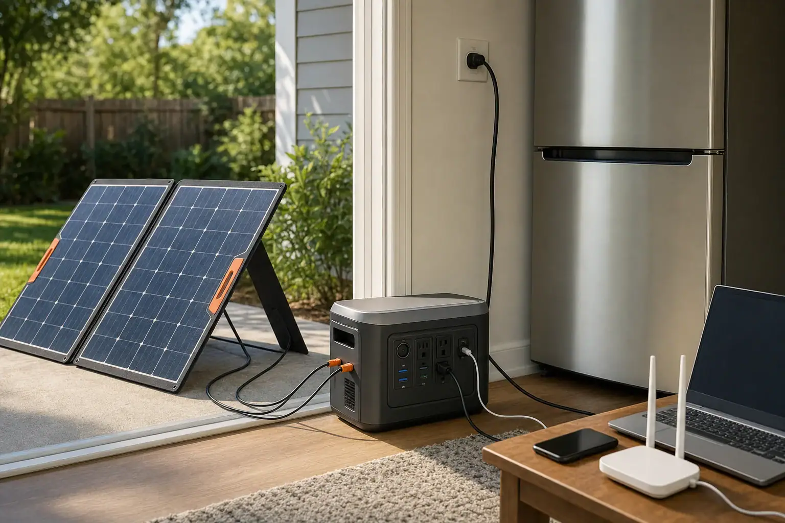
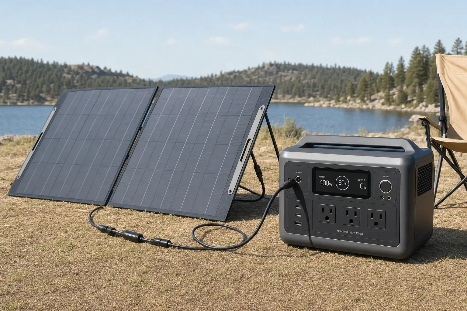
Two portable solar panels charging a 1,000Wh power station outdoors

Most 1,000Wh power stations need one 400-watt panel, two 200-watt panels, or four 100-watt panels for a practical recharge in roughly one sunny day. The exact number depends on the station’s solar input limit, the panels’ rated wattage, available peak sun hours, and normal conversion losses.

Under favorable conditions, a 400-watt solar array may recharge a depleted 1,000Wh battery in about three to five hours of strong sunlight. A 200-watt array commonly needs six to eight equivalent hours, so it may require more than one day when sunlight is limited. Cloud cover, panel angle, temperature, shading, and cable losses can extend charging time.

Panel count alone does not determine charging performance. You must also compare the array’s open-circuit voltage, operating voltage, current, connector type, and total wattage with the power station’s MPPT input range. A larger array will not necessarily charge faster if the station caps incoming solar power.

1. What the Required Solar Panel Count Really Means

The required number of portable solar panels is the number needed to produce enough usable energy within your desired charging window. A 1,000Wh rating means the battery can nominally store approximately 1,000 watt-hours of energy. It does not mean that a 1,000-watt solar panel is required.

Solar panels are rated in watts, which describe power under standardized test conditions. Power stations are rated in watt-hours, which describe stored energy. Multiplying solar power by time gives theoretical energy. For example, a 200-watt panel operating at its full rating for five hours would theoretically produce 1,000Wh.

Real portable panels rarely sustain their nameplate rating all day. Heat, imperfect alignment, atmospheric conditions, charge-controller losses, and changing sun angles reduce output. A reasonable planning assumption is that a portable array may deliver about 65% to 85% of its rated energy during useful sunlight. Performance can be substantially lower in shade or heavy clouds.

For many users, two 200-watt panels represent a practical starting point because a 400-watt array can replenish around 1,000Wh during a good solar day. However, that answer only applies if the power station accepts close to 400 watts and the connected panels stay within its electrical limits.

2. How to Calculate the Number of Panels

Start with the amount of energy that must be replaced. A fully depleted 1,000Wh battery requires approximately 1,000Wh of stored energy, but the panels may need to produce more because charging is not perfectly efficient. Instead of trying to account for every individual loss, use a combined real-world production factor of about 0.65 to 0.85.

Estimated panel count = energy needed ÷ panel wattage ÷ peak sun hours ÷ production factor

Assume that you want to replace 1,000Wh using 200-watt panels, five peak sun hours, and a 75% production factor. One panel could provide approximately 750Wh in that period: 200 watts multiplied by five hours multiplied by 0.75. Dividing 1,000Wh by 750Wh gives 1.33, which must be rounded up to two panels.

Peak sun hours are not the same as total daylight hours. They express the day’s solar energy as an equivalent number of hours at strong standardized sunlight. A location may have ten hours of daylight but only four or five peak sun hours.

The power station’s input ceiling must also be applied. If a station accepts no more than 300 watts of solar input, a 600-watt array may improve production during weak light but cannot deliver 600 watts to the battery. When the array is producing more than the input can accept, the charge controller limits or clips the excess.

Array sizeCommon panel combinationsEstimated energy in 5 peak sun hours at 75%General result for 1,000Wh
100WOne 100W panel375WhUsually requires multiple days
200WTwo 100W panels or one 200W panel750WhMay need more than one good day
400WFour 100W panels or two 200W panels1,500WhOften enough for one good day
600WThree 200W panels2,250WhProvides headroom for shorter or weaker sun
800WFour 200W panels3,000WhUseful only if input limits and electrical ranges allow it
Estimated production before any station-specific input clipping. Example values for illustration.

3. Real-World Solar Panel Sizing Examples

Two 200-watt panels for a one-day recharge

Consider a 1,000Wh power station that accepts up to 500 watts of solar input. With five peak sun hours and a 75% production factor, two 200-watt panels could generate approximately 1,500Wh before station-specific limitations. That provides enough planning margin to replace 1,000Wh despite ordinary losses and periods of reduced output.

The full recharge may still take most of the usable solar day because output is lower in the morning and afternoon. Charging while simultaneously operating appliances also increases the total energy the panels must supply.

Four 100-watt panels for flexible placement

Four 100-watt panels provide the same 400-watt nameplate capacity as two 200-watt panels. Smaller panels may be easier to move or position around minor obstacles, but they require more cables, connectors, and setup space. More connection points can also increase resistance or create additional opportunities for loose connections.

The panels cannot be combined arbitrarily. In a series arrangement, panel voltage adds while current generally remains similar. In a parallel arrangement, current adds while voltage generally remains similar. Only use configurations supported by the panel and power station documentation.

One 200-watt panel for occasional use

A single 200-watt panel can be sufficient when rapid recharging is not important. At a realistic average of 140 to 170 watts during strong conditions, replacing 1,000Wh can require roughly six to eight equivalent hours, plus additional time if loads are running. In many locations, that means charging across two days.

Extra array capacity with a low input limit

Suppose the station accepts 300 watts but is connected to 400 watts of panels within its voltage and current limits. The extra panel capacity may help the array reach the 300-watt ceiling earlier and maintain it longer. It will not make the station accept more than 300 watts. Adding still more panels produces diminishing returns and may violate voltage or current limits if the configuration is incompatible.

4. Common Sizing Mistakes and Troubleshooting Cues

Using nameplate wattage as guaranteed output: A 200-watt panel may produce less than 200 watts because of heat, haze, panel angle, clouds, or controller losses. Briefly seeing 140 to 180 watts from a nominal 200-watt portable panel can be normal under real conditions.

Ignoring the solar input limit: If displayed input stops rising after another panel is added, the station may have reached its wattage or current ceiling. Check the documented maximum input power, MPPT voltage window, and input current rather than assuming the new panel is defective.

Exceeding the voltage range: Connecting panels in series increases voltage. The combined open-circuit voltage must remain below the station’s maximum, including the tendency of panel voltage to rise in cold weather. An incompatible voltage can prevent charging or damage equipment.

Counting daylight instead of peak sun hours: Ten hours between sunrise and sunset does not provide ten hours of rated panel output. Solar harvest is strongest near midday and much lower when the sun is close to the horizon.

Allowing partial shade: A shadow across even part of a panel can reduce output significantly. Trees, roof racks, handles, cables, and nearby equipment are common sources. If input is unexpectedly low, check for shade, clean the panel surface, improve orientation, and inspect external connections.

Charging while using the station: A 150-watt load can consume much of the output from a 200-watt panel. The display may show solar input while the battery percentage rises slowly or remains steady. Compare incoming solar power with the total active load.

Mixing mismatched panels: Panels with different voltages, currents, or electrical characteristics may not operate efficiently together. Compatibility involves more than matching connector shapes. Use combinations specifically supported by the relevant equipment documentation.

5. Solar Charging Safety Basics

Keep the power station dry, ventilated, and out of prolonged direct sun when possible. The panels need sunlight, but the battery enclosure generally does not. High battery temperature can reduce charging speed as internal protection systems limit power.

Confirm polarity, connector compatibility, voltage, and current before connecting an array. Do not force similar-looking connectors together or use improvised adapters. Cables should be fully inserted, undamaged, and rated for the expected outdoor conditions and current.

Do not exceed the station’s maximum open-circuit voltage. Include a cold-weather safety margin because panel voltage can increase as temperature falls. If the necessary series or parallel configuration is unclear, consult the equipment documentation or a qualified solar professional.

Place folding panels on stable surfaces and secure them against wind. Avoid pinching cables under doors, vehicle tires, or panel frames. Discontinue use if a cable, connector, panel junction, or input port becomes unusually hot, damaged, discolored, or wet.

Portable solar equipment should not be used to improvise connections to household wiring. Any integration with home circuits, transfer equipment, or permanent electrical systems should be designed and installed by a qualified electrician in accordance with applicable requirements.

6. Maintaining Panels for Reliable Charging

Dust, pollen, salt residue, bird droppings, and leaf debris can lower panel output. Inspect panel surfaces before use and clean them according to the manufacturer’s care guidance. A soft cloth and appropriate nonabrasive method are generally preferable to harsh chemicals or tools that could scratch the surface.

Check external cables and connectors for cuts, looseness, corrosion, bent contacts, or heat damage. Repeated folding and transport can stress cable entry points. Protective caps should be used when available to keep debris and moisture out of disconnected plugs.

Store portable panels dry, clean, and loosely folded along their intended seams. Do not stack heavy objects on folded panels because concentrated pressure can damage cells or internal conductors. Avoid long-term storage in locations with extreme heat, freezing moisture, or high humidity.

The power station also needs proper storage. Follow its specified storage temperature and periodically check its state of charge. Many battery systems are best stored partially charged rather than completely full or empty, but the recommended percentage and inspection interval vary by battery chemistry and design.

Maintenance itemWhen to checkWhy it matters
Panel surfaceBefore use and when output dropsDirt and residue can block sunlight
Cables and plugsBefore each setupDamage or loose contacts can cause losses and heat
Folding seams and supportsAfter transportWear can affect stability and internal conductors
Power station charge levelPeriodically during storageDeep self-discharge can affect availability and battery health
Stored environmentSeasonallyHeat and moisture can shorten equipment life
A simple inspection schedule for portable solar equipment. Example values for illustration.

Related guides: How to Read Solar Panel Specs for Power Stations: Voc, Vmp, Imp, and Why It MattersOverpaneling Explained: Can You Connect Bigger Solar Panels Than the Input Limit?Solar Safety Basics: Cables, Heat, and Preventing Connector Melt

7. Practical Takeaways and Specs to Look For

For a typical 1,000Wh power station, plan on approximately 400 watts of portable solar capacity if the goal is to recharge in one favorable solar day. That usually means one 400-watt panel, two 200-watt panels, or four 100-watt panels. A 200-watt array is workable when charging speed is less important, while 600 to 800 watts may help in limited sun only when the station supports that much input.

Size the array using energy demand, local peak sun hours, and a realistic production factor. Then verify that the proposed panel configuration remains within the station’s voltage, current, and power limits. If appliances will run during charging, add their energy consumption to the 1,000Wh refill target.

Specs to look for

  • Maximum solar input power: Look for roughly 400 to 800 watts when faster charging is important; this determines how much array output the station can use.
  • MPPT voltage range: Compare a range such as 12 to 60 volts with the panels’ operating voltage; the array must enter this window for efficient charging.
  • Maximum open-circuit voltage: Select a limit with sufficient margin above the array’s combined open-circuit voltage; this is especially important in cold weather.
  • Maximum input current: Values such as 10 to 15 amps are common examples; this limit affects how much current a parallel panel arrangement can deliver.
  • Panel rated wattage: Compare sizes such as 100, 200, or 400 watts; higher wattage reduces panel count but may increase folded size and weight.
  • Panel operating voltage and current: Confirm that the electrical values match the intended series or parallel configuration; connector compatibility alone is not enough.
  • Connector and cable compatibility: Look for secure, correctly polarized connections and appropriately rated cables; unnecessary adapters and long undersized cables can add losses.
  • Conversion efficiency and MPPT control: Look for documented solar charging performance across a useful input range; effective tracking helps capture more energy as sunlight changes.
  • Folded dimensions and weight: Compare portability with output; a large array is useful only if it can be transported, positioned, and secured reliably.
  • Environmental durability: Look for resistance to dust, light moisture, heat, and repeated folding appropriate to expected use; durable construction supports consistent long-term output.

The best panel count is therefore not a fixed universal number. It is the smallest compatible array that can replace your expected energy use within the sunlight and time available, without exceeding the power station’s input specifications.

Frequently asked questions

Can a 100-watt solar panel charge a 1,000Wh power station?

Yes, a 100-watt panel can charge a 1,000Wh power station if its voltage and connector are compatible with the solar input. However, it will usually produce only a few hundred watt-hours in a typical day, so a full recharge commonly takes several days. Actual results depend on peak sun hours, weather, panel angle, and charging losses.

How long does it take to charge a 1,000Wh power station with solar?

Charging time depends on usable solar input rather than panel rating alone. In strong sun, a compatible 400-watt array may replenish the battery in roughly three to five hours of high-output charging, while a 200-watt array may need six to eight equivalent hours. The time increases if the station is powering appliances at the same time.

What solar panel specs matter for a 1,000Wh power station?

Check the power station’s maximum solar input wattage, MPPT operating-voltage range, maximum open-circuit voltage, and maximum input current. Compare those limits with the combined electrical specifications of the panels in their intended series or parallel configuration. Connector type and cable polarity must also be compatible.

Is it a mistake to connect more solar watts than the power station can accept?

Adding modest extra panel capacity can help maintain useful charging output in less-than-perfect sunlight, but the station will not charge above its input limit. The important requirement is that the array remains within the station’s voltage and current limits at all times. Oversizing without checking those electrical limits can prevent charging or damage equipment.

Is it safe to leave portable solar panels connected all day?

It can be safe when the panels, cables, and power station are compatible, undamaged, and used according to their instructions. Keep the power station dry and ventilated, secure panels against wind, and avoid damaged connectors or pinched cables. Disconnect the system if components become unusually hot, wet, discolored, or damaged.

Do clouds and shade reduce portable solar panel output?

Yes, clouds reduce the sunlight reaching the panels, and partial shade can cause a substantial drop in output. Even small shadows from trees, roof racks, handles, or cables may affect performance. Repositioning the panels toward direct sunlight and keeping their surfaces clean can improve charging results.

Solar Adapter Polarity Mistakes: How to Avoid Reverse-Polarity Charging Problems

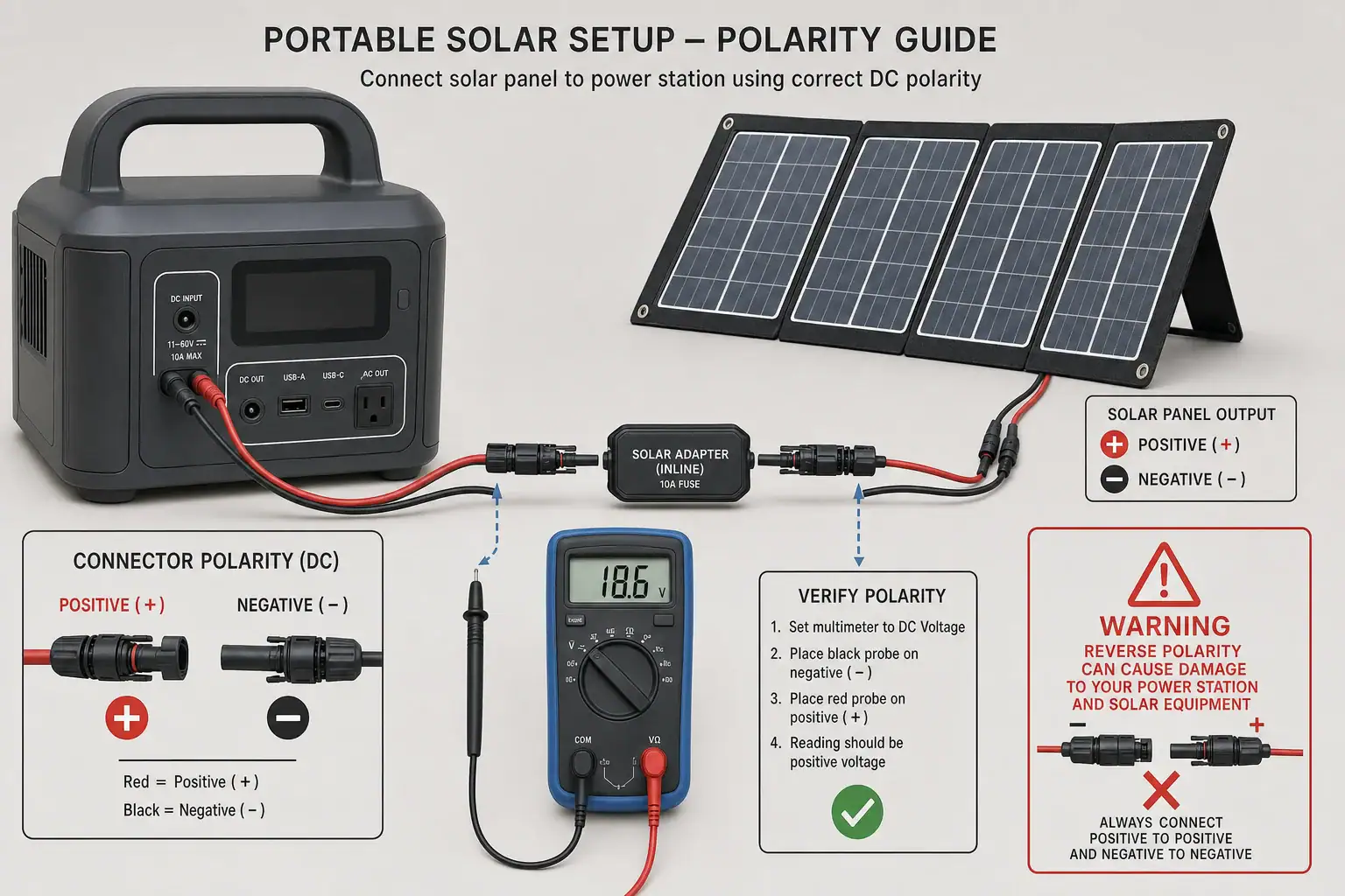
Solar adapter polarity check between a solar panel and portable power station

Reverse-polarity charging happens when a solar adapter sends positive voltage to the portable power station’s negative input contact and negative voltage to its positive contact. The safest solution is to verify the connector pinout, voltage range, open-circuit voltage, and input polarity before making the connection.

A cable can physically fit yet still be electrically incompatible. This is especially common with barrel plugs, coaxial DC adapters, extension cables, and solar connectors whose physical shape does not clearly indicate electrical polarity. A reverse-polarity connection may cause an input error, zero solar watts, repeated charging interruptions, or damage if adequate protection is absent.

Do not assume that matching connector dimensions guarantee compatibility. Check the polarity symbol on the power station, the solar panel output label, and the adapter documentation. If any marking is missing or contradictory, stop and verify the cable with appropriate test equipment or obtain help from a qualified technician.

1. What Solar Adapter Polarity Means and Why It Matters

Polarity describes which conductor carries positive voltage and which carries negative voltage in a direct-current circuit. Solar panels used with portable power stations produce DC electricity, so their positive and negative conductors must reach the corresponding contacts at the power station’s solar input.

On a common barrel connector, one electrical contact is the center pin or inner sleeve and the other is the outer sleeve. Many devices use a center-positive arrangement, but center-negative equipment also exists. Some power stations use multi-contact or aviation-style inputs with their own pin assignments. Similar-looking connectors can therefore have different wiring.

Solar connectors introduce another source of confusion: physical connector gender is not the same as electrical polarity. A connector housing that appears male may contain a female electrical contact, and cable assemblies can reverse the relationship. Positive and negative markings on the actual cable should take priority over assumptions based on shape.

Reverse polarity matters because internal charging electronics are designed for current to enter in one direction. A well-protected input may reject the connection without damage, but protection should not be treated as permission to experiment. Other possible results include a blown replaceable fuse in an approved cable, input protection shutdown, overheated wiring, arcing at a connector, or damage to the charging controller.

2. How Solar Polarity, Voltage, and Connectors Work Together

A compatible solar connection requires more than correct polarity. The panel or array must also remain within the power station’s accepted solar input voltage, current, and power ranges. Correct polarity with excessive open-circuit voltage can still damage an input, while incorrect polarity remains a problem even when voltage is otherwise acceptable.

Solar panel labels commonly list open-circuit voltage, abbreviated Voc, and operating voltage, often shown as Vmp. Voc is the higher voltage measured when the panel is not supplying a load. Because Voc can rise in cold weather, array planning should use the combined cold-condition open-circuit voltage rather than only the nominal or operating value.

Series-connected panels add voltage while current generally stays near the rating of one panel. Parallel-connected panels add available current while voltage remains near the rating of one panel. Parallel branches also require consistent polarity at every junction. One reversed branch can create a hazardous fault instead of simply reducing charging performance.

The adapter must preserve the electrical path from positive to positive and negative to negative. A polarity-reversing adapter intentionally swaps those conductors, while a straight-through adapter preserves them. These products can look nearly identical, so continuity or voltage testing may be necessary when reliable pinout information is unavailable.

Typical compatibility checks for a solar charging connection. Example values for illustration.
ItemExample markingWhat to confirm
Power station input11–50 V DC, 10 A, 400 WPanel voltage, current, and polarity fit the input specification
Solar panelVoc 24.3 V, Vmp 20.4 VVoc remains below the input maximum in expected temperatures
Barrel adapterCenter positiveCenter and sleeve match the power station polarity symbol
Extension cablePositive and negative labeledThe cable is straight-through and has adequate conductor size
Array connectionTwo panels in seriesCombined Voc is acceptable and end-to-end polarity is correct

3. Real-World Reverse-Polarity Examples

A barrel plug that fits but does not charge

A user connects a solar panel through a barrel adapter that has the correct outer diameter. The power station shows zero input watts even in direct sunlight. The panel and station both operate normally with their original cables. Inspection reveals that the station expects center-positive polarity, while the adapter is wired center-negative. Physical fit did not establish electrical compatibility.

An extension cable that reverses the output

A panel charges the station correctly with a short factory-supplied lead. After an extension is added, charging stops and the input briefly reports an error. The extension uses matching connector shells but crosses the positive and negative conductors internally. Removing that extension restores operation, making the added cable the most likely fault location.

Confusing connector housing gender with polarity

A solar cable is assembled according to the appearance of its connector housings rather than the positive and negative markings. The completed adapter presents reversed polarity at the power station end. This mistake occurs because housing gender, metal-contact gender, and electrical polarity are separate characteristics.

A mixed array with one reversed branch

Two nominally similar panels are combined in parallel, but one branch is connected backward. Instead of doubling useful current, the branches oppose each other and may drive current through an unintended path. This is not a normal troubleshooting condition. The array should be disconnected and inspected by someone familiar with DC solar connections.

4. Common Mistakes and Troubleshooting Cues

The most common mistake is selecting an adapter solely by connector size. Barrel plugs may differ in outer diameter, inner diameter, pin depth, contact design, and polarity. A loose or partially fitting plug can also create intermittent charging that resembles a polarity problem.

Another frequent error is trusting wire color without verification. Red usually indicates positive and black usually indicates negative, but repaired, relabeled, or nonstandard cables may not follow that convention. Molded arrows and plus or minus symbols can also refer to connector alignment rather than electrical polarity.

Typical reverse-polarity cues include zero input power in strong sunlight, an immediate solar input fault, charging that begins only after changing adapters, or a protective cable fuse that opens repeatedly. However, these symptoms are not conclusive. Shade, low irradiance, excessive panel voltage, poor contact, damaged wiring, input current limits, and a disabled solar charging setting can produce similar behavior.

Troubleshoot by simplifying the system without modifying it. Disconnect the solar source, inspect labels and connector condition, and compare the station’s required pinout with the adapter’s documented pinout. Remove unnecessary extensions, splitters, and converters. If a known-compatible original cable works but an added adapter does not, the adapter or its connection is a strong suspect.

A digital multimeter can confirm DC voltage and polarity when used by a person familiar with its ratings and safe operation. A positive reading generally means the red probe is touching the positive contact relative to the black probe. A negative sign indicates the relationship is reversed. Avoid shorting closely spaced contacts with probe tips, and do not test exposed conductors in wet conditions. When connector identification or meter use is uncertain, use a qualified solar or electrical technician.

5. Safety Basics for Solar Charging Connections

Disconnect the solar panel before changing adapters or rearranging an array. Covering or turning a portable panel away from direct sunlight can reduce production, but it may not eliminate voltage. Treat panel leads as energized whenever the panel is exposed to light.

Never force a connector, hold a loose plug in position, or repeatedly reconnect a cable that produces sparks, heat, odor, discoloration, or fault messages. Stop using any adapter with cracked insulation, bent contacts, corrosion, melted plastic, or exposed copper. A damaged connector can introduce resistance and heating even when its polarity is correct.

Do not open a portable power station, alter its battery pack, bypass input protection, or replace a protective device with a higher-rated substitute. These actions can defeat safeguards and create fire or shock risks. Use only external cables and adapters with suitable voltage, current, temperature, and environmental ratings.

Keep connectors dry and supported so cable weight does not pull against the input port. Make connections with dry hands and place the power station in a ventilated location consistent with its operating instructions. If a permanent solar installation, building wiring, rooftop array, or grounded system is involved, consult a qualified electrician or solar professional rather than improvising an adapter.

6. Cable Maintenance, Inspection, and Storage

Label compatible adapters at both ends with their connector type and verified polarity. A simple center-positive, center-negative, positive, or negative marking can prevent mix-ups when several similar cables are stored together. Keep polarity-reversing adapters physically separated from straight-through adapters.

Before each use, inspect connectors for dirt, corrosion, looseness, bent contacts, and heat damage. Wipe dry, de-energized connector exteriors with a clean cloth. Do not insert metal tools, liquids, or abrasive material into contacts. Protective caps help keep dust and moisture away during transport and storage.

Coil cables loosely rather than folding them sharply near molded strain reliefs. Tight bends can break conductors internally while leaving the outer insulation intact. Store adapters in a dry location away from direct heat, heavy objects, and chemicals that could degrade insulation.

Recheck polarity after any cable replacement, field repair performed by a qualified person, or change to a panel array. Also confirm that combined array voltage remains within the station’s input range. An adapter that was correct for one panel configuration may not be appropriate for a different series or parallel arrangement.

Inspection schedule for solar adapters and charging cables. Example values for illustration.
WhenCheckReason
Before each connectionPolarity labels, connector fit, and visible damagePrevents reversed or poor-contact connections
After transportBent contacts and crushed cable sectionsTravel can damage conductors and connector shells
After an input faultAdapter pinout and panel open-circuit voltageSeparates polarity faults from voltage incompatibility
SeasonallyCorrosion, label readability, and cable flexibilityFinds gradual environmental deterioration
After changing the arrayEnd-to-end polarity and combined VocConfirms the new configuration remains compatible

Related guides:MC4, Anderson, DC Barrel: Solar Connectors and Adapters ExplainedHow to Read Solar Panel Specs for Power Stations: Voc, Vmp, Imp, and Why It MattersSolar Extension Cables and Voltage Drop: When Cable Length Starts to MatterSolar Safety Basics: Cables, Heat, and Preventing Connector Melt

7. Practical Takeaways and Specs to Look For

Correct solar adapter polarity means the panel’s positive output reaches the power station’s designated positive input contact and the negative output reaches its negative contact. Verify this relationship from reliable markings or test results rather than connector appearance. Polarity is only one part of compatibility; voltage, current, wattage, connector dimensions, and cable capacity must also match.

If charging stops immediately after an adapter or extension is added, disconnect the system and compare that component’s pinout with the station’s requirements. Do not use repeated trial-and-error connections as a diagnostic method. A reverse-polarity protection feature can reduce risk, but it does not make an incompatible cable acceptable.

Specs to look for

  • Input polarity: Look for an explicit center-positive, center-negative, or numbered-pin diagram; it identifies the required electrical path and prevents assumptions based on connector shape.
  • Solar input voltage range: A range such as 12–50 V DC should accommodate operating voltage and cold-weather Voc; staying within range protects the charging controller.
  • Maximum open-circuit voltage: Compare a limit such as 50 V with the array’s temperature-adjusted Voc; series panels can exceed the input limit even when nominal voltage seems acceptable.
  • Input current limit: A rating such as 10 or 15 A shows how much current the station can accept; extra panel current may be clipped and requires appropriately rated connectors and cable.
  • Maximum solar input power: Values such as 200–500 W indicate the charging capacity under suitable voltage conditions; panel wattage alone does not guarantee full input power.
  • Connector dimensions and pinout: Look for exact barrel dimensions or a numbered contact map; similar-looking plugs may fit poorly or carry reversed polarity.
  • Reverse-polarity protection: Look for documented electronic shutdown or replaceable inline protection; it may limit damage from an error but should not replace verification.
  • Cable voltage and current rating: Choose ratings above the expected array output, such as 60 V DC and 15 A for a lower-powered portable setup; adequate capacity reduces overheating and voltage drop.
  • Wire gauge and length: Shorter, heavier cable such as 12–14 AWG may reduce voltage drop compared with a long, thin extension; stable voltage supports more consistent charging.

Keep a verified, labeled adapter with the power station whenever possible. That small organizational step reduces the chance that a physically compatible but electrically reversed cable will be selected during travel, emergency use, or equipment changes.

Frequently asked questions

How can I tell whether a solar adapter is center-positive or center-negative?

Check the polarity symbol or pinout diagram on the adapter, power station, or product documentation. For a barrel connector, the diagram identifies whether the center contact or outer sleeve is positive. If the marking is unavailable or unclear, verify with a properly rated multimeter or seek qualified assistance.

What solar adapter specs and features should I check before connecting a panel?

Confirm the connector dimensions, electrical pinout, voltage rating, current rating, and cable capacity. Also compare the panel or array’s open-circuit voltage with the power station’s maximum solar input voltage. Documented reverse-polarity protection is useful, but it does not replace verifying compatibility.

Can a solar adapter fit correctly but still have the wrong polarity?

Yes. Connector shape and dimensions only indicate mechanical fit, not how the positive and negative conductors are wired. A physically compatible barrel plug, extension, or conversion cable can still reverse the electrical path.

Is it safe to test different solar adapters until one starts charging?

No. Repeatedly trying unverified adapters can expose the charging input, cable, or panel to reverse polarity or excessive voltage. Disconnect the solar source first and verify polarity, pinout, and voltage limits before making a connection.

Why does solar charging stop after I add an extension cable?

The extension may have a wiring fault, reversed polarity, poor connector contact, excessive voltage drop, or an insufficient current rating. Remove the extension and test with a known-compatible cable if possible. If charging resumes, inspect the extension’s pinout and condition before using it again.

Does reverse-polarity protection mean any solar cable is safe to use?

No. Protection may shut down the input or reduce damage from a wiring mistake, but its behavior and limits vary by device. An incompatible cable can still cause charging faults, blown protection components, overheating, or damage if protection is absent or exceeded.

Portable Solar Panel Waterproof Ratings: What Rain, Dew, and Splash Resistance Mean

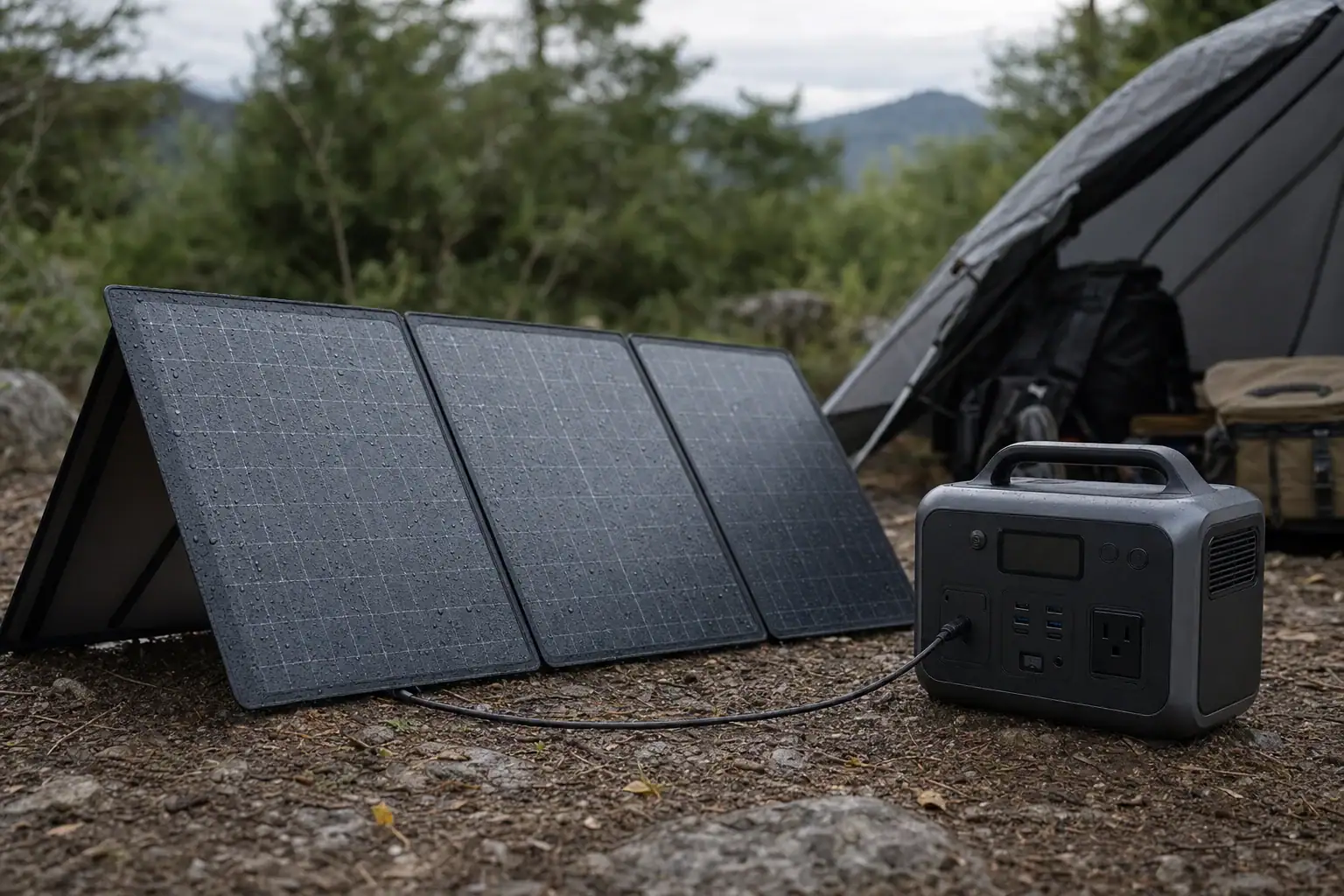
Water droplets on a portable solar panel charging a protected power station outdoors

A portable solar panel is safe in rain only when its stated waterproof or water-resistance rating covers the complete panel and the exposure stays within that rating. Many panels tolerate light rain or splashes, but that does not mean their connectors, junction box, controller, or attached portable power station can get wet.

Look for an IP rating, such as IPX4, IP65, or IP67, rather than relying on general terms like weather-resistant or outdoor-ready. Rain resistance, splash resistance, dew protection, and temporary immersion are different levels of protection. The panel surface may shed water while moisture still reaches a cable connection or electronics enclosure.

For reliable outdoor solar charging, check which components the rating applies to, protect electrical connections, and avoid prolonged exposure. Even a highly rated panel should be dried before folding or storage because trapped moisture can promote corrosion, staining, odor, and insulation damage.

1. What Portable Solar Panel Waterproof Ratings Mean

A waterproof rating describes how an enclosure was tested against water entering it. For portable solar panels, the most common reference is an ingress protection, or IP, code. The code may apply to the panel body, its junction box, a permanently attached cable assembly, or another specifically identified component.

An IP code normally contains two characters after “IP.” The first position covers protection from solid particles such as dust. The second covers water. An “X” means that no rating is stated for that position; it does not mean zero protection, but it also does not prove protection.

For example, IP65 indicates a dust-tight enclosure and resistance to water jets under defined test conditions. IPX4 indicates splash resistance, with no declared dust rating. IP67 adds protection against temporary immersion under specified laboratory conditions. These ratings describe controlled tests, not an unlimited guarantee for storms, flooding, salt spray, or continuous outdoor installation.

The distinction matters because portable panels combine several materials and components. A laminated photovoltaic surface can resist water while fabric edging absorbs it. A sealed junction box may remain dry while exposed connector contacts collect moisture. The least-protected part of the charging system often determines whether outdoor use is appropriate.

2. How Rain, Dew, and Splash Exposure Affect a Panel

Rain reaches equipment from above, but wind can drive it sideways or underneath a folded-panel stand. Water can also follow a cable into a connector or enclosure. This movement, sometimes called water tracking, means placing a connector beneath the panel does not always keep it dry.

Splashes are usually brief and lower in volume than sustained rain. An IPX4-type rating is commonly associated with splashing from multiple directions, but it should not be interpreted as protection from forceful hose spray, puddle immersion, or hours of heavy rainfall. Higher water ratings indicate testing against more demanding exposure, yet test duration, nozzle pressure, enclosure condition, and installation position still matter.

Dew is different because it forms directly on cool surfaces when air reaches its dew point. It may appear inside folds, around connector shells, or beneath clear protective layers where ventilation is limited. Condensation can occur even when no rain fell. Repeated wet-dry cycles can leave mineral deposits and gradually corrode contacts.

Water resistance also changes with age and use. Creases, scratched coatings, worn cable glands, damaged edge seals, and distorted connector gaskets can reduce protection. Folding designs receive repeated mechanical stress, so their condition matters as much as the original rating.

Common interpretations of portable solar panel water ratings. Example values for illustration.
Rating or claimTypical meaningWhat it does not establish
No stated IP ratingWater protection is not confirmed by a standardized ratingSafe use in rain, dew, or splashes
IPX4Resistance to splashing water during a defined testResistance to jets, immersion, or prolonged storms
IP65Dust-tight enclosure with resistance to water jetsSafe submersion or protection for unrelated accessories
IP67Dust-tight enclosure with temporary immersion protection under test conditionsContinuous underwater use or operation with wet connectors
Weather-resistantGeneral outdoor durability claimA specific, independently defined level of water ingress protection

3. Real-World Rain, Dew, and Splash Examples

Light rain during charging

A rated panel may continue collecting solar energy during a brief shower, although cloud cover will reduce output. The complete setup is not automatically rain-safe. A portable power station with no suitable water rating should remain in a dry, ventilated shelter, and cable connections should be kept above wet ground and protected from direct rain.

Morning dew at a campsite

A panel left outside overnight may be covered with dew before sunrise. The front surface may tolerate this moisture, but folding the panel while wet can trap water against fabric, wiring channels, or connector pockets. Waiting for the assembly to dry reduces the chance of corrosion and mildew during storage.

Splashing near a pool, boat, or shoreline

Occasional freshwater droplets may fall within a splash rating, but saltwater and chemically treated water are more aggressive than clean test water. Residue can remain conductive and corrosive after the visible water evaporates. A waterproof designation should not be treated as approval for marine use unless that environment is specifically covered by the documentation.

A panel lying in a puddle

Shallow water can reach seams, cable exits, and connector contacts that would stay dry in ordinary rain. An immersion rating for the panel enclosure does not necessarily cover detachable plugs or a connected power station. Remove the equipment from the wet area without handling exposed electrical contacts while they are energized.

Heavy wind-driven rain

Strong wind can overturn a panel, strain cables, and push water into openings from unusual angles. Mechanical damage may become a greater risk than the rainfall itself. Portable panels should not be left unattended during severe weather, regardless of their stated IP code.

4. Common Rating Mistakes and Troubleshooting Cues

One common mistake is assuming that an IP rating covers every item in a solar charging kit. Product documentation may rate only the panel’s laminated section or junction box. Extension cables, adapters, controllers, USB modules, and power-station input ports may have lower protection or none at all.

Another mistake is treating “waterproof” as permanent. Seals wear, connectors loosen, and flexible materials develop stress around folds. Inspect the system if solar input becomes intermittent after moisture exposure. Output that repeatedly starts and stops may indicate weak sunlight, shading, a loose plug, moisture at a contact, or a protective circuit responding to an abnormal condition.

Visible fogging under the panel surface, water inside a junction box, green or white deposits on contacts, swollen laminate, peeling edges, burnt odors, or unusual heat are warning signs. Stop using affected equipment and disconnect it according to its normal shutdown instructions. Do not open sealed housings or attempt to bypass protection circuits.

Low output during rain is not necessarily water damage. Dense clouds can reduce panel wattage sharply, and partial shading may have an outsized effect on some panel layouts. After the equipment is fully dry, test it in clear sun with compatible input settings. If performance remains unstable or physical damage is visible, seek inspection or replacement through an appropriate service provider.

5. Outdoor Solar Charging Safety Basics

Keep the portable power station, charge controller, adapters, and unprotected connectors dry unless each item has a suitable rating for the conditions. Position electronics above ground where runoff cannot collect, while maintaining the ventilation clearances specified for the equipment. A plastic bag wrapped tightly around operating electronics is not a safe shelter because it can trap heat and condensation.

Do not connect or disconnect wet plugs with the system energized. If rain begins and the setup is not rated for it, stop charging using the equipment’s normal controls, move to a dry location when it is safe, and allow components to dry completely. Never use damaged connectors, cracked cable insulation, or contacts showing corrosion.

Secure the panel against wind without puncturing its laminate or blocking ventilation. Avoid placing it where roof runoff, sprinklers, waves, or vehicle spray can exceed ordinary rainfall. During lightning, flooding, severe wind, or rapidly worsening weather, discontinue outdoor use and move away from exposed equipment when conditions allow.

Water resistance does not address every electrical hazard. Confirm that the panel’s open-circuit voltage, current, connector type, and polarity are compatible with the power station’s solar input. If a setup involves permanent building wiring or other fixed electrical systems, consult a qualified electrician rather than improvising connections.

6. Drying, Cleaning, Maintenance, and Storage

After wet use, place the disconnected panel in a shaded, ventilated area and allow both sides, seams, pockets, stands, and cables to dry. Do not fold or pack it until hidden fabric layers and connector recesses are dry. Avoid concentrated heat, open flames, or high-temperature air, which can deform laminate and weaken adhesives.

For routine cleaning, remove loose dust with a soft cloth and use a lightly damp cloth when the manufacturer permits it. Abrasive pads, pressure washers, harsh solvents, and forceful spray can scratch the light-transmitting surface or drive water past seals. Residue from saltwater or chlorinated splashes should be addressed promptly using the cleaning method approved for the panel.

Inspect cable glands, edge seals, hinges, kickstands, and connector caps before trips and after severe exposure. Protective caps should be clean and fully seated during storage, but only after the contacts are dry. Store the panel in a cool, dry place without heavy objects pressing on folded cells or sharply bending cables.

Record changes in normal output under similar sunlight. A gradual decline can have many causes, including surface dirt, cell damage, aging, or connector resistance. Maintenance cannot restore a failed seal or delaminated surface, so equipment with water intrusion should be evaluated rather than returned immediately to service.

Illustrative inspection cues after moisture exposure. Example values for illustration.
ObservationPossible concernPractical response
Droplets only on the front surfaceNormal rain or dew exposureDisconnect if necessary and dry before folding
Moisture inside a connectorTracking water or a poorly seated capKeep de-energized and allow complete drying
Fogging beneath laminatePossible seal failure or delaminationStop use and obtain qualified evaluation
Green or white contact residueCorrosion or dried mineral depositsDo not reconnect until appropriately inspected
Intermittent input after dryingConnector, cable, shading, or internal damageTest in clear sun and discontinue use if instability continues

Related guides: Water, Humidity, and IP Ratings: What “Splash Resistant” Really MeansMC4, Anderson, DC Barrel: Solar Connectors and Adapters ExplainedSolar Safety Basics: Cables, Heat, and Preventing Connector MeltHow to Read Solar Panel Specs for Power Stations: Voc, Vmp, Imp, and Why It Matters

7. Practical Takeaways and Specs to Compare

A water rating is useful only when its scope and limitations are clear. Match the rating to likely conditions, including dew, wind-driven rain, ground splash, and storage while damp. Treat the panel, connectors, adapters, and power station as separate components because each may have a different level of protection.

For occasional camping or emergency charging, good cable management and a dry location for electronics can matter as much as a high panel rating. For frequent outdoor exposure, prioritize documented test ratings, sealed connection points, durable edge construction, and clear operating guidance rather than broad marketing language.

Specs to look for

  • Panel IP rating: Look for a clearly stated code such as IPX4, IP65, or IP67 and match it to expected splashes, jets, or temporary immersion; this provides more context than a generic waterproof claim.
  • Rating scope: Confirm whether the rating covers the full panel, junction box, cable exits, and attached modules; an excluded component can become the main water-entry point.
  • Connector protection: Look for capped or gasketed connectors with an identified protection level when mated and unmated; this matters because exposed contacts are vulnerable to moisture and corrosion.
  • Surface and laminate material: Compare durable, UV-resistant outer layers and sealed edges designed for repeated folding; these features help preserve water resistance as the panel ages.
  • Operating temperature range: A typical documented range might extend from below freezing to roughly 140°F; temperature cycling can affect seals, adhesives, and condensation risk.
  • Cable length: Around 6 to 15 feet may provide flexibility to keep the power station under dry cover while the panel remains in sunlight; excessive extension length can also add voltage loss.
  • Input compatibility: Check open-circuit voltage, operating voltage, current, polarity, and connector type against the power station’s input range; compatibility prevents failed charging and electrical stress.
  • Warranty coverage: Review whether water ingress, seal failure, or outdoor exposure is covered or excluded; the wording indicates how the claimed protection is intended to be used.
  • Drying and storage guidance: Look for explicit instructions on cleaning, drying, folding, and connector care; clear maintenance requirements help preserve performance after rain or dew.

The safest assumption is that any component without a documented water rating must stay dry. A rated portable solar panel can be useful in changing weather, but it should not be submerged, pressure-washed, packed wet, or left outside indefinitely unless its documentation specifically supports those conditions.

Frequently asked questions

Can portable solar panels get wet in the rain?

Some portable solar panels can tolerate rain when their documented IP rating covers that type of exposure. The rating may apply only to the panel body or junction box, not to connectors, adapters, charge controllers, or a connected power station. Check the product documentation and keep unrated components dry.

Is IPX4 waterproof enough for a portable solar panel?

IPX4 generally indicates protection against splashing water from multiple directions under defined test conditions. It does not establish protection against water jets, immersion, prolonged storms, or wet electrical connections. Whether it is sufficient depends on the expected conditions and the rating scope for the entire setup.

What portable solar panel specs and features matter most for wet weather?

Look for a clearly stated IP rating and confirm exactly which parts it covers, including the panel, junction box, cable exits, and connectors. Sealed edges, durable laminate, protected cable glands, connector caps, and manufacturer drying instructions can also affect real-world durability. Input compatibility and a dry location for connected electronics remain important even with a highly rated panel.

What is the most common mistake when using a solar panel in wet conditions?

A common mistake is assuming that a panel’s water rating protects every component in the charging system. Unrated plugs, extension cables, adapters, and power-station input ports may be vulnerable even when the panel surface is water-resistant. Another frequent error is folding and storing the panel before seams, pockets, and connectors are fully dry.

Is it safe to use a portable solar panel with wet connectors?

No. Avoid connecting, disconnecting, or operating wet connectors while the system is energized because moisture can contribute to corrosion, poor contact, or electrical faults. Stop charging using normal controls when appropriate, keep components de-energized, and allow them to dry completely before inspection and reconnection.

Can morning dew damage a folding solar panel?

Occasional dew on an intact panel surface may not cause immediate damage, but repeated wet-dry cycles can affect contacts, folds, and edge materials over time. Dew can also collect in connector recesses and fabric layers where it is less visible. Let the panel dry thoroughly before folding or packing it away.

Can You Charge a Portable Power Station Through a Window With Solar Panels?

Portable power station charging from a solar panel placed behind a sunny window

Yes, you can charge a portable power station through a window with solar panels, but the panel will usually generate less power than it would outdoors. Window glass, low-E coatings, insect screens, shadows, and an unfavorable panel angle can all reduce the sunlight reaching the solar cells.

Charging will work only if the panel’s voltage and current are compatible with the station’s solar input. Important terms include solar input, MPPT voltage range, open-circuit voltage, input limit, and charging time. Even a compatible system may charge slowly or cycle on and off when indoor light is weak.

Placing a panel behind glass can be convenient when outdoor installation is impractical, during temporary use, or in apartments where equipment cannot be left outside. However, it is generally a compromise rather than the best setup. Direct outdoor sunlight, safe placement, and correct electrical specifications provide more consistent charging.

1. What Charging Through a Window Means and Why It Matters

Charging through a window means placing a solar panel indoors so sunlight passes through one or more panes of glass before reaching the photovoltaic cells. The panel connects to the portable power station’s dedicated solar or DC input. The power station’s internal charge controller then converts the panel’s variable output into usable battery-charging power.

A solar panel does not require outdoor air to operate; it requires enough usable light. It can therefore produce electricity behind clear glass. The problem is that a window reflects and absorbs part of the solar energy. Modern insulated windows may have multiple panes, tint, ultraviolet filtering, or low-emissivity coatings that cause additional losses.

This matters because a panel rated at 200 watts under laboratory test conditions may produce only a fraction of that rating behind a window. Lower output increases charging time and may fall below the power station’s minimum operating threshold. Indoor placement can also make the panel hotter, and photovoltaic output typically declines as cell temperature rises.

2. How Solar Charging Through Glass Works

Solar cells produce direct-current electricity when photons reach the semiconductor material. Clear glass allows much of the visible light through, but transmission is not perfect. Reflections occur at each glass surface, while coatings and tint can block selected wavelengths. Screens, dirt, blinds, window frames, and partial shadows create further losses.

Panel angle and sunlight intensity

Output is highest when sunlight strikes the panel close to perpendicular. A vertically placed panel behind a window may perform reasonably when the sun is low but poorly when the sun is high overhead. Because the sun moves, a productive location in the morning may be shaded by afternoon. Diffuse daylight can produce some electricity, but it is far weaker than direct sun.

Electrical compatibility

The panel’s operating voltage should fall within the power station’s MPPT voltage range. Its open-circuit voltage must remain below the station’s maximum solar-input voltage, including the increase that can occur in cold conditions. Available panel current may exceed the station’s accepted current only if the equipment documentation permits current limiting; voltage must not exceed the stated maximum.

The station also has a maximum solar wattage. Connecting more rated panel wattage does not force excess power into the battery because a compatible controller normally limits intake. However, incompatible voltage, connectors, polarity, or wiring can prevent charging or damage equipment.

Typical effects of window placement. Example values for illustration.
Panel conditionPossible output from a 200 W panelMain influence
Outdoors in strong, direct sun140–190 WAngle, temperature, and weather
Behind clear single-pane glass90–160 WReflection and panel angle
Behind coated double-pane glass50–130 WMultiple panes and coatings
Behind glass with a screen or partial shade15–90 WObstruction and uneven illumination

3. Real-World Window Charging Examples

Consider a portable power station with a 1,000-watt-hour battery and a 200-watt solar panel. Outdoors, the panel might deliver an average of 150 watts during several favorable hours. After conversion losses and charging overhead, adding roughly 600 watt-hours could take about four to five hours of productive sunlight.

If the same panel produces an average of 90 watts behind a window, adding that energy might require seven hours or more. The process may extend across multiple days because the window receives direct sun for only part of each day. Charging also slows near a full state of charge as the battery-management system reduces input.

A smaller 100-watt panel behind coated glass might deliver 30 to 60 watts. That can be useful for maintaining charge or replacing energy used by phones, lights, and other small devices, but it may not keep pace with a continuously powered refrigerator or other substantial load.

Partial shade produces a less predictable result. A narrow window frame shadow across one section of a panel can reduce output disproportionately, depending on the panel’s cell layout and bypass diodes. Moving the panel a few inches or changing its orientation may produce a larger improvement than expected.

4. Common Mistakes and Troubleshooting Cues

Expecting the panel’s rated wattage

Panel ratings are measured under standardized light and temperature conditions. Indoor placement rarely matches those conditions. Compare the power station’s displayed solar input in several positions rather than assuming the panel is defective. Test outdoors in safe, direct sunlight to establish a useful baseline.

Using incompatible voltage or connectors

A connector that physically fits does not prove electrical compatibility. Verify the panel’s open-circuit voltage, operating voltage, polarity, connector type, and maximum current against the power station’s input specifications. An incorrect adapter or reversed polarity can result in zero input even when the panel is illuminated.

Ignoring minimum startup power

Some power stations need a minimum voltage or wattage before the solar controller activates. Weak light can cause the input display to alternate between zero and a small reading. This often indicates changing sunlight, shading, or insufficient voltage rather than a failed battery.

Overlooking screens, tint, and shadows

Remove movable obstructions such as blinds without damaging the window or creating excessive heat. If practical, compare output with and without an insect screen. Watch for narrow shadows from mullions, handles, nearby buildings, roof overhangs, and trees.

Charging while running heavy loads

The battery percentage may continue to fall if connected appliances consume more power than the panel supplies. Check both solar input and AC or DC output. A station receiving 70 watts while supplying a 120-watt load has a net battery discharge of at least 50 watts, plus conversion losses.

5. Safety Basics for Panels, Windows, and Cables

Keep the portable power station dry, ventilated, and within its specified operating-temperature range. Do not place it in a sealed window recess where direct sun can cause heat buildup. Leave clearance around cooling vents, and avoid covering the unit or placing it on easily damaged fabric.

Support the panel securely so it cannot fall, press against fragile glass, or obstruct an emergency exit. Do not place a rigid panel where concentrated heat, sharp edges, or excessive weight could damage the window. Panels mounted outside need appropriate structural support and weather-resistant hardware rather than temporary cords or unsecured hooks.

Route the cable without crushing it in a closing window or creating a trip hazard. A pinched cable can damage insulation and create resistance, heat, or an intermittent connection. Use only compatible, adequately rated cables and adapters. Do not open the power station, alter the battery, bypass protection circuits, or improvise connections to household wiring.

If a permanent exterior panel, wall penetration, grounding arrangement, or connection near building electrical systems is being considered, consult a qualified electrician or installer familiar with local requirements.

6. Maintenance and Storage for Reliable Solar Charging

Dust and fingerprints reduce the light reaching a panel, especially when window glass is also dirty. Clean the panel and the accessible side of the window according to their care instructions. Use nonabrasive materials, avoid harsh chemicals, and allow all surfaces and connectors to dry before use.

Inspect cables periodically for cuts, flattened sections, loose contacts, discoloration, or unusual warmth. Keep connector ends protected from moisture and debris during storage. Repeatedly bending a cable at the plug can weaken its conductors and create intermittent charging.

For long-term storage, follow the power station’s recommended charge level and recharge interval. Avoid leaving the battery fully depleted for extended periods. Store the station in a cool, dry location away from direct sun, freezing conditions, and sources of heat. Foldable panels should be dry and clean before being folded so grit does not scratch their surfaces.

Simple inspection guide. Example values for illustration.
ItemSuggested checkReason
Panel and windowBefore a charging sessionDust and shade reduce output
Cables and plugsEvery few usesDamage can interrupt charging
Stored power stationEvery 2–4 monthsHelps prevent deep discharge
Input readingWhen conditions changeConfirms useful solar production

Related guides: Can You Charge a Portable Power Station with Solar Panels?How to Read Solar Panel Specs for Power Stations: Voc, Vmp, Imp, and Why It MattersShading and Angle: How Placement Changes Solar Charging SpeedSolar Safety Basics: Cables, Heat, and Preventing Connector Melt

7. Practical Takeaways and Specs to Look For

Window solar charging is feasible when direct sunlight reaches a compatible panel, but it should be treated as reduced-output charging. Start by comparing the panel and power station specifications, then test several indoor positions while watching the input wattage. A clean, unshaded panel facing the sun as directly as possible will usually perform best.

If indoor output is too low, the most effective improvement is often moving the panel outdoors to a safe, secure location while keeping the power station protected indoors. A longer compatible cable may help, although excessive cable length or undersized conductors can cause voltage loss. Do not exceed voltage limits in an attempt to compensate for poor sunlight.

Specs to look for

  • MPPT voltage range: Look for a range that comfortably includes the panel’s normal operating voltage, such as 15–50 volts, because the controller must receive an acceptable voltage to charge efficiently.
  • Maximum solar-input voltage: Compare this value with the panel’s open-circuit voltage and allow a cold-weather margin; staying below the maximum protects the input electronics.
  • Solar-input wattage: A range such as 200–500 watts may support faster charging when adequate panel capacity and sunlight are available.
  • Maximum input current: Check values such as 10–15 amps against the panel or array current because the station may cap usable power even when voltage is compatible.
  • Minimum solar startup requirement: Look for low-voltage and low-power startup behavior if the panel will often operate behind glass or in variable light.
  • Panel open-circuit voltage: Choose a panel whose highest expected voltage remains safely below the station’s input ceiling, especially in cold, bright weather.
  • Connector type and polarity: Confirm direct compatibility or the availability of a correctly wired, adequately rated adapter to avoid unreliable or reversed connections.
  • Input display resolution: A display or monitoring system that shows real-time solar watts makes it easier to optimize panel position and identify shading or connection problems.
  • Operating-temperature range: Look for limits appropriate to the intended room or outdoor conditions because excessive heat can reduce charging power and battery longevity.

Through-window charging is best for convenience, maintenance charging, and modest daily energy needs. For predictable charging times or larger loads, unobstructed outdoor sunlight generally provides substantially better performance.

Frequently asked questions

How much slower is charging a portable power station through a window?

Charging through a window is often noticeably slower because glass, coatings, screens, shade, and panel angle reduce the light reaching the solar cells. Actual output can range from a modest reduction behind clean clear glass to a substantial reduction behind tinted or coated multi-pane windows. Checking the station’s live solar-input reading is the most reliable way to estimate charging time.

Can a solar panel charge a power station through double-pane or low-E glass?

It may charge through double-pane or low-E glass if enough direct sunlight reaches the panel and the electrical connection is compatible. These windows can reduce solar transmission more than plain single-pane glass, so output may be too low for useful charging at certain times of day. A short test in direct sun can show whether the station’s controller remains active.

What solar panel and power station specs matter for window charging?

Check that the panel’s normal operating voltage fits within the power station’s MPPT input range and that its open-circuit voltage stays below the maximum allowed solar-input voltage. Also confirm connector type, polarity, current limits, maximum input wattage, and any minimum voltage or power needed to start charging. These specifications matter regardless of whether the panel is indoors or outdoors.

Why does my power station show zero solar input behind a window?

Zero input can result from weak or indirect light, a shadow across the panel, tinted glass, a screen, or a panel angle that receives little sunlight. It can also indicate incompatible voltage, incorrect polarity, a loose adapter, or a controller that has not reached its startup threshold. Testing the same panel outdoors in direct sunlight helps separate a light-level issue from a connection or compatibility issue.

Is it a mistake to use a solar panel’s rated wattage to predict indoor charging time?

Yes. The rated wattage is measured under standardized test conditions and is not a guarantee of real-world output, particularly behind glass. Use the measured input watts shown by the power station and account for shorter periods of direct sun, battery charging losses, and any loads running at the same time.

Is it safe to leave a solar panel and portable power station by a window?

It can be safe when the panel is stable, the power station has ventilation, and cables are not pinched by the window or placed where they create a trip hazard. Keep the battery unit dry and out of excessive heat, and do not block exits or place heavy or rigid panels where they could damage glass. Use only compatible cables and adapters, and follow the equipment instructions.

Best Solar Panel Angle for a Portable Power Station: Faster Charging Without Guesswork

Best solar panel angle for charging a portable power station

The best solar panel angle for a portable power station is the angle that points the panel face as directly at the sun as possible. For a stationary setup around midday, a tilt close to your geographic latitude is a useful starting point, but adjusting it for the season and time of day can produce more energy.

Correct solar panel tilt reduces reflection and increases the sunlight reaching the cells. That can raise input wattage, shorten charging time, and help the system remain within its productive MPPT range. Direction, shade, panel temperature, peak sun hours, and the power station’s solar charging input also affect the result.

You do not need precision instruments to find a productive angle. Start with a seasonal estimate, aim the panel toward the sun, and compare the displayed solar watts after each small adjustment. The highest stable reading is usually more useful than a generic angle copied from a chart.

1. What the best solar panel angle means and why it matters

Solar panel angle, or tilt, is measured between the panel surface and level ground. A panel lying flat has a tilt of 0 degrees, while a vertical panel has a tilt of 90 degrees. Orientation, also called azimuth, describes the compass direction the panel faces. Both influence charging performance.

A panel collects the most direct sunlight when its face is perpendicular to the sun’s rays. If the sun is high, the panel generally needs a shallower tilt. When the sun is low in the morning, afternoon, or winter, a steeper angle is more effective. The ideal position therefore changes continuously rather than remaining fixed all day.

Angle matters because sunlight arriving at a sharp angle spreads across more surface area and more of it may be reflected. A poorly aimed panel can still generate power, especially under bright or partly cloudy conditions, but its output will usually be lower. Portable panels make adjustment practical, so a few deliberate changes during the day can increase total watt-hours without adding panel capacity.

2. How sun position, latitude, season, and charging limits work together

Latitude provides a practical baseline for a panel that will stay in one position for several hours. As a general starting point, use a tilt roughly equal to local latitude for balanced year-round exposure. Subtract about 10 to 15 degrees during summer, when the sun travels higher, and add about 10 to 15 degrees during winter, when it remains lower. These are starting estimates rather than universal settings.

Direction is equally important. In the Northern Hemisphere, a fixed panel generally faces toward true south; in the Southern Hemisphere, it generally faces true north. Around solar noon, this orientation captures the strongest part of the day’s sunlight. A portable panel used earlier or later can instead be rotated toward the sun. True direction may differ from a magnetic compass reading depending on location.

Electrical limits can hide the benefit of better alignment. A panel may be capable of 200 watts while the power station accepts only 150 watts through its solar input. Once the input limit is reached, changing the angle may not increase the displayed wattage. The panel array must also remain within the station’s accepted input voltage, current, and total power ranges. Angle adjustment cannot correct an incompatible connection.

Clouds and haze increase diffuse light, which arrives from many directions. Precise aiming matters less under heavy overcast, although a moderately tilted, unobstructed panel may still outperform one facing away from the brightest part of the sky.

Seasonal tilt starting points by latitude. Example values for illustration.
LatitudeSummer starting tiltYear-round starting tiltWinter starting tilt
20°5°–10°20°30°–35°
30°15°–20°30°40°–45°
40°25°–30°40°50°–55°
50°35°–40°50°60°–65°

3. Real-world angle examples for portable solar charging

Midday summer charging

Consider a portable panel used at 40 degrees latitude on a clear summer day. A 25- to 30-degree tilt facing the equator is a sensible starting position near midday. If the power station shows 118 watts, change the tilt by about 5 degrees, wait for the reading to stabilize, and compare. If output rises to 126 watts, continue in that direction once more. If it falls, return to the better position.

Low winter sun

At the same location in winter, a 50- to 55-degree tilt may better face the lower sun. A shallow summer setting could lose substantial direct exposure even when the sky looks bright. Snow-covered ground may reflect additional light, but snow or frost on the cells blocks production and should not be treated as a substitute for correct alignment.

Morning-to-afternoon adjustment

For a full charging day, begin with the panel aimed toward the morning sun. Near midday, rotate it toward the equator-facing direction and adjust the tilt for the higher sun. In the afternoon, turn it westward and use a steeper tilt as the sun descends. Two or three adjustments are often enough; constant tracking is rarely necessary for a portable setup.

Using the shadow method

If no angle tool is available, use the panel’s shadow as a visual guide. When the panel points more directly at the sun, its shadow generally appears compact and falls mostly behind it rather than stretching strongly to one side. Fine-tune using the power station’s input display because shadows alone cannot account for clouds, cell temperature, or charging limits.

4. Common angle mistakes and troubleshooting slow solar charging

  • Adjusting tilt but not direction: A correctly tilted panel facing away from the sun can perform poorly. Rotate the panel first, then fine-tune its tilt.
  • Leaving the panel flat all day: Flat placement can work when the sun is nearly overhead, but it is usually less productive in the morning, afternoon, and cooler seasons.
  • Chasing rapidly changing readings: Passing clouds and MPPT adjustments can make input fluctuate. Wait roughly 30 to 60 seconds after moving the panel before comparing stable readings.
  • Ignoring partial shade: A narrow shadow from a branch, cable, handle, railing, or panel stand can reduce output disproportionately. Inspect the full cell surface as the sun moves.
  • Expecting nameplate output: Rated wattage is measured under standardized laboratory conditions. Heat, haze, atmospheric angle, wiring loss, and charging electronics usually make real output lower.
  • Overlooking battery state: Some power stations reduce charging power as the battery approaches full charge or when the battery is unusually hot or cold. A falling input reading is not always an angle problem.
  • Exceeding the solar input ceiling: If the displayed power repeatedly stops at the same value in strong sun, the station may have reached its wattage or current limit.
  • Using incompatible electrical specifications: Verify connector compatibility and the array’s voltage, current, and power against the power station’s accepted range. Do not assume that a physically fitting plug is electrically compatible.

For troubleshooting, establish a clean baseline: use an unshaded panel, place it in open sunlight, aim it directly, and check that all approved connections are fully seated. Compare input at similar times on clear days. If output remains abnormally low, inspect accessible cables and connectors for visible damage and consult the equipment documentation rather than opening or modifying either device.

5. Safety basics when positioning portable solar panels

Set the panel on stable ground or a support designed for its size and weight. Secure it against wind, especially at steep angles where it can act like a sail. Do not place rocks or sharp objects directly on the cells, and keep walkways and emergency access clear.

Avoid damaged, pinched, or tightly coiled cables. Keep connectors clean, dry, and off wet ground unless the equipment is specifically designed for those conditions. Never connect or disconnect damaged electrical contacts, and do not exceed the power station’s accepted open-circuit voltage. Electrical voltage can remain present whenever the panel is illuminated.

Panels can become hot in direct sun. Use their frame, stand, or designated handles when adjusting them, and avoid touching hot cell surfaces. Stop using equipment that smells unusual, shows melting or swelling, sparks, or displays repeated fault warnings. Do not open the power station, modify the panel, bypass protection devices, or connect the system to household wiring. Consult a qualified electrician for any installation involving a building electrical system.

6. Maintaining accurate positioning and storing the equipment

Clean cells produce more dependable angle comparisons. Dust, pollen, bird droppings, salt residue, and water spots can create localized shading. Follow the panel’s cleaning instructions, use a soft nonabrasive material, and let the equipment cool before cleaning. Avoid harsh chemicals and high-pressure spray unless expressly permitted by the manufacturer.

Inspect the stand, hinges, fasteners, cable strain reliefs, and connector surfaces periodically. A loose stand may allow the tilt to drift, while a worn hinge may collapse in wind. Marking a few commonly used tilt positions on an adjustable stand can make seasonal setup faster, but the final input reading should still guide fine adjustments.

Before storage, disconnect the equipment as directed, remove moisture and dirt, and fold or pack the panel without sharply bending cells or cables. Store it in a dry, temperature-controlled location away from heavy objects and direct sunlight. Protect connectors with their supplied caps where available. Follow the power station’s instructions for storage charge level and periodic battery checks.

Portable solar panel care and positioning checks. Example values for illustration.
CheckSuggested timingWhy it matters
Remove visible surface debrisBefore each charging sessionReduces localized shading
Inspect stand and hingesEvery few usesHelps the panel hold its selected tilt
Inspect accessible cables and connectorsBefore use and after transportIdentifies visible wear or contamination
Review seasonal tiltEvery 2–3 monthsAccounts for changes in solar elevation
Dry and pack equipmentAfter useLimits corrosion and transport damage

Related guides: Solar Panel Series vs Parallel: Which Is Better for Charging a Power Station?How to Read Solar Panel Specs for Power Stations: Voc, Vmp, Imp, and Why It MattersShading and Angle: How Placement Changes Solar Charging SpeedSolar Safety Basics: Cables, Heat, and Preventing Connector Melt

7. Practical takeaways and specs to compare

Start with a panel tilt near local latitude, make it shallower in summer and steeper in winter, and face it toward the sun. Then use the power station’s live input reading to find the best position for the actual conditions. Adjust in small increments and allow the reading to stabilize. If watts do not improve, check orientation, shade, temperature, battery state, and electrical limits before assuming the angle is wrong.

For all-day charging, repositioning the panel two or three times can capture more energy than leaving it fixed. However, total watt-hours matter more than the single highest watt reading. A brief midday peak does not compensate for several hours of poor morning and afternoon alignment.

Specs to look for

  • Adjustable tilt range: Look for a stand covering roughly 15 to 60 degrees or more; a broad range supports summer, winter, and low-sun positioning.
  • Stand stability: Look for rigid, independently adjustable supports and secure contact with the ground; stable hardware prevents angle drift and wind-related falls.
  • Solar input wattage: Compare limits such as 200, 400, or 800 watts with the intended array; adequate capacity prevents the station from clipping useful panel output.
  • MPPT voltage range: Confirm that the panel or array operating voltage fits within the accepted range, such as 12 to 60 volts; proper matching allows efficient power tracking.
  • Maximum input voltage: Check that array open-circuit voltage remains safely below the stated ceiling in cold weather; exceeding this value can damage equipment.
  • Input current limit: Compare array current with limits such as 10, 15, or 20 amps; excess available current may be clipped even when wattage capacity appears sufficient.
  • Live input display: Look for real-time watts and, ideally, accumulated watt-hours; these measurements make angle comparisons and daily performance easier to evaluate.
  • Cable length and gauge: Choose enough length for unshaded placement with conductors sized for the expected current; undersized or unnecessarily long cables increase voltage loss.
  • Environmental protection: Look for clearly stated resistance to dust, splashes, and outdoor exposure; suitable protection matters when adjusting equipment around damp ground or changing weather.

No single tilt guarantees maximum output in every location or season. The most reliable approach combines a latitude-based starting angle, direct observation of the sun, and the power station’s measured input. That method accounts for local weather, terrain, shade, panel design, and charging limits without relying on guesswork.

Frequently asked questions

What is the best solar panel angle for a portable power station?

The best solar panel angle for a portable power station is the position that keeps the panel face as close to perpendicular to the sun’s rays as practical. Start near your local latitude for a fixed setup, then use a shallower tilt in summer and a steeper tilt in winter. Check the station’s stable solar-input reading after small adjustments to identify the most productive position.

Should a portable solar panel face south or north?

In the Northern Hemisphere, a panel left in one position around midday generally faces true south. In the Southern Hemisphere, it generally faces true north. For portable use in the morning or afternoon, rotating the panel toward the sun can improve charging compared with leaving it fixed in the midday direction.

How often should I adjust a solar panel during the day?

For many portable charging sessions, two or three adjustments are sufficient: one in the morning, one near midday, and one in the afternoon. The benefit depends on sky conditions, available time, and whether the power station has already reached its solar-input limit. Compare total watt-hours over the day rather than focusing only on the highest momentary watt reading.

What is a common mistake that reduces portable solar charging output?

A common mistake is changing the panel’s tilt without first turning the panel toward the sun. Even a well-tilted panel can produce less power if its direction is wrong or part of the cell surface is shaded. After repositioning, wait for the input reading to stabilize before deciding whether the change helped.

What solar panel and power station specs matter most for charging performance?

Check the power station’s accepted solar-input voltage range, maximum open-circuit voltage, input-current limit, and maximum input wattage before connecting a panel or array. An adjustable and stable stand, an appropriate cable length and gauge, and a live watt display also make it easier to improve real-world charging. A physically matching connector does not by itself confirm electrical compatibility.

Is it safe to leave a portable solar panel outside while charging?

It can be safe when the panel is supported on stable ground, secured against wind, and used within the environmental conditions specified by its manufacturer. Keep cables and connectors dry and undamaged, avoid placing the equipment in walkways, and do not exceed the power station’s input limits. Disconnect and stop using the equipment if there are signs of damage, overheating, sparking, melting, or repeated fault warnings.

Bifacial Solar Panels and Portable Power Stations: When the Extra Output Helps

Elevated bifacial solar panel charging a portable power station over a reflective surface

Bifacial solar panels can charge a portable power station faster when their rear side receives substantial reflected or indirect sunlight and the station can accept the additional power. The extra output helps most on bright days when a panel is elevated over snow, pale gravel, sand, concrete, or another reflective surface. It helps less when the panel lies flat, its back is shaded, or the power station has already reached its solar input limit.

Real results depend on rear-side exposure, surface reflectivity, panel angle, temperature, shading, and MPPT controller behavior. Electrical compatibility also matters: the array’s open-circuit voltage, operating voltage, short-circuit current, connector type, and rated watts must fit the portable power station’s solar input specifications. Bifacial gain is therefore not a fixed bonus. It is additional production that may improve charging time, low-light performance, or daily energy harvest under suitable conditions, but only when panel placement and the receiving equipment allow that energy to be used.

1. What bifacial solar panels mean and why they matter

A conventional monofacial panel is designed to generate electricity mainly from sunlight striking its front surface. A bifacial panel uses solar cells and a rear construction that can also convert light reaching the back into electricity. The rear side does not need direct sunlight at the same intensity as the front; reflected and diffuse light can contribute.

The practical benefit is usually described as bifacial gain: the extra energy produced compared with front-side production alone. This gain is not the same as the panel’s bifaciality factor. Bifaciality indicates how effectively the rear side responds relative to the front under standardized testing, while actual gain depends heavily on the installation environment.

For portable power stations, the distinction between momentary watts and total daily watt-hours matters. Rear-side light might raise midday output, extend useful production during morning or afternoon, or soften losses from minor front-side shading. Any of these effects can increase daily energy harvest. However, the station receives no additional benefit when its charge controller is already clipping input at its maximum accepted wattage or current.

Bifacial designs are most useful for portable setups that can leave open space behind the panel. Some rigid panels naturally support this arrangement. Foldable or fabric-backed panels may obtain little rear-side gain if their backing blocks light or if they are placed directly on the ground.

2. How rear-side gain and solar input limits work

Rear-side production starts with albedo, which is the fraction of incoming light reflected by a surface. Fresh snow and some bright roofs can reflect substantial light. Light-colored gravel, sand, and concrete often offer moderate reflection. Dark soil, asphalt, grass, and water generally provide less useful reflection, although conditions and sun angle can change the result.

Panel clearance is equally important. A bifacial panel placed flat against a surface cannot receive much rear illumination. Raising it creates an air gap and allows reflected light to spread across more of the back. Tilt can improve front-side solar alignment while also changing which areas of the rear receive reflected light. Wide supports, cables, equipment, and nearby objects may cast rear-side shadows that reduce the gain.

The portable power station’s MPPT solar charge controller then determines how much available power can enter the battery. The panel or array must stay within the controller’s voltage range and maximum open-circuit voltage. It must also respect accepted current and power limits. Extra available wattage above an input-power ceiling may be clipped, while excessive voltage can create a more serious compatibility problem.

Temperature affects these calculations. Solar-panel voltage tends to increase in cold conditions, so an array that appears compatible at a mild temperature could exceed an input voltage ceiling during cold weather. Meanwhile, hot panels usually produce less voltage and power. Manufacturer specifications and an appropriate cold-weather voltage margin should guide array sizing.

ConditionLikely rear-side contributionPractical implication
Panel flat on dark groundMinimalExpect performance close to front-side output alone
Panel elevated over grassLowClearance may help, but the surface reflects limited light
Panel elevated over pale concreteModerateRear production may provide a useful charging increase
Panel elevated over bright snowPotentially highCheck cold-weather voltage and the station’s input ceiling
Array already at input limitAvailable but clippedRear gain may not increase peak charging watts
Example values for illustration. Actual gain varies with weather, geometry, equipment, and surface conditions.

3. Real-world examples of when extra output helps

Camping on a light-colored surface

Consider a 200-watt bifacial panel elevated above pale gravel. If front-side conditions support 150 watts and reflected light adds 15 watts, the panel could deliver about 165 watts before cable and conversion losses. A power station accepting 300 watts of solar input can use the increase, potentially shortening the bulk-charging period. A station limited to 150 watts would probably clip most of the extra peak output.

Winter use over snow

An elevated panel over clean snow can receive strong rear illumination. A nominal 400-watt array might briefly produce more than its expected front-only output under favorable sun, temperature, and reflection. This can be valuable when winter daylight is short. Cold conditions can also raise open-circuit voltage, however, so electrical headroom is more important than pursuing the highest possible wattage.

Partly cloudy charging

Under broken clouds, output may rise and fall quickly. Diffuse and reflected light reaching the rear can improve energy collection during some intervals, but cloud-edge effects may also create brief output spikes. A properly sized MPPT input can manage normal variations without relying on a narrow voltage margin.

Base camp with all-day charging

A small increase sustained for several hours can matter more than a short midday peak. For example, an average gain of 20 watts over five productive hours represents roughly 100 watt-hours before system losses. That may be enough to offset several hours of lighting, device charging, communications equipment, or another modest load.

Hot, dark campsite

A panel resting near dark ground in hot weather may show little bifacial advantage. Rear exposure is poor, and elevated cell temperature reduces output. In this situation, better airflow, front-side orientation, and shade-free placement may improve charging more than the bifacial construction itself.

4. Common mistakes and troubleshooting cues

Expecting the nameplate rating plus a guaranteed bonus: Solar ratings are measured under defined test conditions. Actual front output changes with irradiance, temperature, angle, and cleanliness, while rear gain is site-dependent. Treat advertised bifacial gain percentages as conditional rather than automatic.

Blocking the rear surface: Placing the panel flat on a blanket, vehicle roof, or ground surface largely defeats rear-side collection. If output is no better than expected from a monofacial panel, check for open space, reflected light, rear shading, and opaque panel backing.

Confusing watt limits with voltage limits: A charge controller may safely clip surplus watts under a compatible configuration, but that does not make excess voltage acceptable. Compare the array’s open-circuit voltage with the station’s maximum solar input voltage, including cold-weather effects.

Using incompatible series or parallel arrangements: Series connections increase voltage, while parallel connections increase available current. Either arrangement can exceed an input specification if it is not planned correctly. Mixed panels may also operate below their individual potential because of mismatched electrical characteristics.

Overlooking cable losses: Long, undersized, damaged, or loosely connected cables can reduce power and create heat. If the station reports unexpectedly low input, inspect accessible connectors for secure engagement, visible damage, contamination, and excessive warmth without opening either device.

Testing while the battery is nearly full: A power station often reduces charging power at a high state of charge to protect the battery. Compare panel performance when the battery has room to accept substantial energy. Also disable or account for loads that may make the displayed net charging rate misleading.

Comparing different moments: Solar output can change within seconds. A meaningful comparison uses similar sun angle, cloud cover, panel temperature, orientation, battery state, and loads. An external solar meter can help when it is correctly rated, but the power station’s display is often sufficient for broad comparisons.

5. Safety basics for bifacial solar charging

Electrical ratings remain the primary safety boundary. Never connect an array whose possible open-circuit voltage exceeds the portable power station’s stated solar input maximum. Allow additional voltage margin for low temperatures. Current, power, connector polarity, and cable ratings should also match the equipment documentation.

Use connectors and adapters intended for the expected voltage and current. Similar-looking connectors are not necessarily wired with the same polarity. Confirm compatibility before connection, keep contacts dry and clean, and stop using cables that are cracked, deformed, corroded, or unusually hot.

Secure panels against wind. Elevating a panel can improve rear-side exposure, but it also increases wind loading. Use a stable support appropriate for the panel and terrain, and do not place a panel where it can fall onto people, vehicles, cables, or the power station.

Maintain ventilation around both devices. Do not cover the power station with the panel or place it in standing water to shorten the cable run. Keep the battery unit within its specified operating temperature range and away from concentrated reflected light that could cause excessive heating.

Portable solar equipment should not be improvised into household wiring. Connections involving home circuits, electrical panels, transfer equipment, or permanent building installations require properly listed equipment and a qualified electrician where applicable. Do not open equipment, modify battery packs, bypass protection circuits, or alter connectors without approved instructions.

6. Maintenance, transport, and storage

Clean front and rear panel surfaces as recommended for the panel material. Dust, pollen, mud, snow residue, and salt film can reduce output. Use gentle methods that do not scratch coatings or stress seals, and avoid cleaning a very hot panel with cold water. Inspect edges, junction boxes, supports, and accessible cables for damage.

Transport bifacial panels with protection for both faces. Rear glass or transparent backsheet damage can undermine durability even when the front looks intact. Do not stack sharp hardware against the panel, and avoid bending rigid modules or folding portable modules beyond their designed hinges.

Before storage, dry the panel and connectors completely. Coil cables loosely rather than creating tight bends near strain-relief points. Store panels where they will not be crushed, exposed to persistent moisture, or subjected to extreme heat. Follow the power station’s guidance for storage charge level and periodic battery checks.

Keep simple performance notes if the system is used regularly. Recording weather, surface type, panel angle, peak input, and approximate daily energy can reveal gradual losses or poor placement. A sudden decline may indicate new shading, dirt, connector damage, controller limiting, or a battery that is too full, hot, or cold to accept normal charging power.

Portable setupFront-side powerPossible rear gainUsable station input
200-watt panel over dark soil145 W3 W148 W if the input limit permits
200-watt panel over pale gravel145 W18 W163 W if the input limit permits
400-watt array over snow330 W65 W300 W with a 300-watt input ceiling
400-watt array with partial rear shade330 W20 W350 W with sufficient controller capacity
Example values for illustration. These figures are not performance guarantees and exclude some conversion and cable losses.

Related guides: How to Read Solar Panel Specs for Power Stations: Voc, Vmp, Imp, and Why It MattersSolar Input Voltage for Power Stations: How to Stay Inside Voc and Amp LimitsOverpaneling Explained: Can You Connect Bigger Solar Panels Than the Input Limit?Shading and Angle: How Placement Changes Solar Charging Speed

7. Practical takeaways and specs to look for

Bifacial solar panels provide the clearest advantage when they are elevated, exposed on both sides, and positioned over a reflective surface. The additional output is useful only if the portable power station can accept it. For many users, daily watt-hours and charging reliability matter more than the highest instantaneous reading.

Before buying or combining equipment, compare the complete voltage, current, power, connector, and environmental specifications rather than matching rated watts alone. Plan enough input headroom for rear-side gain and changing weather, especially when using multiple panels.

Specs to look for

  • Maximum solar input voltage: Look for a ceiling comfortably above the array’s cold-weather open-circuit voltage; a wider margin reduces the risk that low temperatures push voltage out of range.
  • MPPT operating voltage range: Confirm that the array’s normal operating voltage falls inside the range, such as a panel operating near 30 to 40 volts with an input range broad enough to track it efficiently.
  • Maximum solar input power: Compare the station’s accepted watts with realistic front output plus possible bifacial gain; for example, a 500-watt input can use more of a 400-watt array’s favorable-condition output than a 300-watt input.
  • Maximum input current: Check whether parallel panels or a high-current module could exceed the accepted amperage; current headroom helps prevent avoidable clipping.
  • Panel bifaciality rating: Look for a clearly stated rear-to-front response, often expressed as a percentage; it indicates rear sensitivity but does not guarantee the same percentage of real-world gain.
  • Front-side rated power: Use the standard front rating as the baseline for array planning, then treat rear production as variable additional energy rather than guaranteed capacity.
  • Panel construction and rear transparency: Look for glass-glass construction or a transparent rear layer with minimal obstruction; an opaque backing cannot provide meaningful bifacial collection.
  • Connector and cable ratings: Verify polarity, weather resistance, voltage, current, and wire size; correctly rated cables reduce losses, heating, and adapter problems.
  • Operating temperature range: Compare both panel and power station ranges with expected conditions, such as freezing winter use or hot summer surfaces, because temperature affects voltage, charging acceptance, and output.

The extra output helps most when it adds usable energy during a limited charging window without violating the station’s input limits. Good placement, adequate rear clearance, reflective surroundings, safe electrical margins, and realistic expectations are more important than the bifacial label by itself.

Frequently asked questions

Do bifacial solar panels charge a portable power station faster?

They can charge faster when reflected or diffuse light reaches the rear surface and the power station has unused solar input capacity. The difference may be small on dark ground or when the rear side is blocked, but it can be more useful over bright, reflective surfaces with adequate panel clearance.

How much extra power can a bifacial solar panel produce?

Extra production is variable rather than guaranteed because it depends on surface reflectivity, panel height, tilt, weather, rear shading, and temperature. A modest gain sustained over several hours can add meaningful daily watt-hours even if the peak-watt increase is limited.

What specs matter when choosing bifacial solar panels for portable power stations?

Compare the panel or array open-circuit voltage, operating voltage, current, rated power, connector type, and polarity with the station’s solar input specifications. Also consider the MPPT operating range, maximum accepted power and current, panel rear transparency, bifaciality rating, and cold-weather voltage margin.

Is it a mistake to place a bifacial solar panel flat on the ground?

Usually, yes, if the goal is to benefit from rear-side generation. A panel placed flat has little space for light to reach the back, especially over dark surfaces; elevating it safely over a brighter surface generally provides a better opportunity for bifacial gain.

Do bifacial solar panels work on cloudy days?

Yes, bifacial panels can produce electricity in cloudy conditions because both diffuse sky light and reflected light can reach the cells. Total output will generally be lower than in direct sun, and the amount of rear-side benefit still depends on panel placement and the surrounding surface.

Are bifacial solar panels safe to use with a portable power station?

They are safe when the complete solar setup stays within the station’s stated voltage, current, power, polarity, and connector limits. Never exceed the maximum solar input voltage, allow for higher panel voltage in cold weather, use correctly rated cables, and secure elevated panels against wind.

Solid-State Batteries and Portable Power Stations: What Could Change?

Portable power station with solid-state battery concept diagram

Solid-state batteries could make portable power stations lighter, safer, faster to charge, and longer lasting, but they will not magically remove every limit. The biggest potential changes are higher energy density, improved cycle life, better thermal stability, and possibly faster charge rates if the rest of the power station is designed to handle them.

For buyers comparing future portable power stations, the important questions will still sound familiar: inverter watts, surge watts, runtime, AC output, solar input limit, USB-C PD profile, battery chemistry, and warranty language. A solid-state battery may improve the battery pack itself, but the inverter, charger, battery management system, cooling design, and ports will still determine what the unit can actually run.

In other words, solid-state technology could be a meaningful upgrade, not a shortcut around basic electrical limits. Understanding what may change helps you read future spec sheets without assuming every new label means better real-world performance.

What solid-state batteries mean for portable power stations

A solid-state battery replaces the liquid or gel-like electrolyte found in many lithium-ion batteries with a solid electrolyte. In practical terms, the electrolyte is the material that lets ions move between the battery electrodes during charging and discharging. Changing that material can affect energy density, safety behavior, charging speed, operating temperature, and lifespan.

For portable power stations, those changes matter because the battery is usually the heaviest and most expensive part of the unit. If solid-state cells store more usable energy in the same space, a future power station could offer more watt-hours without becoming larger. If the cells tolerate deeper cycling and higher temperatures, the unit may keep more of its original capacity after years of use.

However, the battery is only one part of the system. A portable power station is a battery pack, inverter, charge controller, DC outputs, AC outlets, display, cooling system, and battery management system packaged together. A better cell chemistry can help, but it cannot make a 600-watt inverter run a 1,500-watt heater continuously. It also cannot make a low solar input limit accept more panel wattage than the charge controller allows.

That is why solid-state power stations should be evaluated as complete systems. The chemistry may be the headline, but the useful value is measured in runtime, recharge time, output capability, safety protections, weight, cycle rating, and how clearly the manufacturer states limits.

How solid-state battery technology works at a practical level

In a conventional lithium-ion cell, ions move through a liquid electrolyte between the anode and cathode. In a solid-state design, ions move through a solid material instead. That solid material may be ceramic, polymer, sulfide-based, oxide-based, or a hybrid approach. Each type has different strengths and manufacturing challenges.

The possible benefit is that some solid electrolytes may allow denser cell structures and more stable operation. In certain designs, solid-state cells may also reduce the risk of leakage and may be less prone to some failure modes associated with flammable liquid electrolytes. This is why solid-state batteries are often discussed in terms of thermal stability and safety.

Another key concept is internal resistance. Lower resistance can support better efficiency and less heat under load, while high resistance can limit fast charging or high-power output. Portable power stations stress batteries in several ways: running an inverter, accepting solar input, charging from AC, and feeding DC ports. A solid-state pack must handle those currents consistently, not just perform well in a lab cell.

The battery management system remains essential. It monitors voltage, current, temperature, charging limits, cell balancing, and fault conditions. Even if solid-state cells are more stable, the system still needs protection against overcharge, over-discharge, overheating, short circuits, and excessive load. Future units may advertise solid-state chemistry, but the quality of the control electronics will still shape long-term reliability.

AreaWhat could improveWhy it matters in a power station
Energy densityMore watt-hours in the same size or weightLonger runtime or easier carrying
Cycle lifeSlower capacity loss over repeated useBetter value for camping, backup, or daily cycling
Thermal behaviorGreater stability under heat or heavy loadLess stress during inverter use and charging
Charge acceptancePotentially faster charging when electronics allow itShorter recharge windows from AC or solar
PackagingThinner or more flexible cell layouts in some designsNew form factors and better internal space use
Solid-state battery concepts compared with common portable power station concerns. Example values for illustration.

Real-world examples of what might change

Imagine a small portable power station used for phones, lights, a laptop, and a small fan. If solid-state cells increase energy density, the same carry weight might offer more usable watt-hours. That could mean an overnight camping setup runs longer without jumping to a heavier size class. It might also mean a compact unit keeps a physically smaller shape while offering the runtime of a larger current model.

For home backup use, the most noticeable change may be longevity. A power station that sits ready for outages and is also used for occasional solar charging can age from both time and cycles. If solid-state batteries deliver improved cycle life and calendar life in consumer products, the unit may retain more capacity after years of seasonal use. That matters because a battery rated at 1,000 watt-hours when new may not deliver the same runtime after repeated cycling and storage.

For mobile workers, faster charging could be useful, but only if the whole system supports it. A solid-state pack may be capable of high charge rates, yet the AC charger, solar charge controller, heat management, and input limit determine the actual recharge time. A unit with a 300-watt AC input will not recharge like a unit with a 1,000-watt input just because both use advanced cells.

For high-demand loads, solid-state chemistry may improve voltage stability and heat tolerance, but inverter size still rules. A portable power station with a 1,000-watt continuous inverter may run a refrigerator, coffee maker, or power tool only if the running watts and surge watts are within its output rating. The battery chemistry can help sustain the load, but it does not replace inverter capacity.

There may also be design tradeoffs. Early solid-state models could cost more, have conservative charge limits, or use hybrid chemistries rather than a fully solid electrolyte. Some may prioritize safety and cycle life over maximum fast charging. Others may focus on compact size. The label alone will not tell the full story.

Common assumptions to avoid and troubleshooting cues

One common mistake is assuming solid-state automatically means unlimited runtime. Runtime is still based mainly on usable watt-hours and the power draw of your devices. A 100-watt load uses about 100 watt-hours per hour before conversion losses. If the power station has 1,000 usable watt-hours, that load may run for several hours, but not indefinitely. Inverter losses, standby drain, temperature, and battery reserve all reduce the simple math.

Another mistake is confusing battery capability with output capability. If a future unit has advanced cells but a modest inverter, it may still shut down when a device has high startup surge. Refrigerators, pumps, compressors, and some tools can briefly require several times their running watts. If the surge watts rating is too low, the chemistry will not prevent an overload.

A third issue is focusing only on fast charging. Fast charging is useful when you have limited time, but it produces heat and depends on the input hardware. If a power station charges slowly, the cause may be the AC input limit, solar controller range, panel placement, cable losses, temperature protection, or a low-power USB-C PD profile. Solid-state batteries may improve charge tolerance, but input design still controls the number you see on the display.

Watch for vague claims. Phrases like next generation battery, advanced solid electrolyte, or safer chemistry are not enough by themselves. Look for measurable details such as watt-hours, continuous output, surge output, cycle rating, operating temperature range, AC input watts, solar input voltage range, and warranty terms. If those details are missing, it is difficult to compare the product responsibly.

Troubleshooting cues will remain similar. If a device will not run, compare its starting and running watts with the power station output rating. If runtime is shorter than expected, check the device wattage, inverter mode, temperature, battery state of charge, and whether AC or DC conversion is being used. If solar charging is weak, check sun angle, panel voltage, input limit, and whether panels are wired within the allowed range. Do not open the power station or bypass protections to solve performance issues.

Safety basics for solid-state portable power stations

Solid-state batteries are often described as safer because some designs may reduce flammable liquid electrolyte risks and improve thermal stability. That does not mean they are risk-free. Any battery that stores a meaningful amount of energy can be damaged by impact, short circuits, overcharging, overheating, water exposure, or incompatible charging equipment.

The safest approach is to treat future solid-state power stations with the same respect as any lithium-based power station. Use the supplied or approved charging method, keep vents clear, avoid covering the unit during heavy charging or discharging, and keep it away from standing water, direct flames, and enclosed hot spaces. Do not use a unit that shows swelling, cracking, unusual odor, melted plastic, repeated error codes, or unexplained heat.

For home backup, avoid improvising connections to household wiring. A portable power station can safely power individual appliances through its outlets when loads are within rating. Connecting any generator or power station to home circuits requires proper equipment and a qualified electrician. This is especially important to prevent backfeed hazards and equipment damage.

Also consider location. During long AC charging, solar charging, or high inverter output, place the power station on a stable, dry, nonflammable surface with room for airflow. Keep children and pets away from cords. Use extension cords only when they are properly rated for the load and in good condition. Solid-state chemistry may improve safety margins, but safe use still depends on the complete setup.

Maintenance and storage in a solid-state future

Maintenance will likely become easier if solid-state batteries reach their expected durability, but storage habits will still matter. Batteries age from time, temperature, and state of charge. Even a more stable chemistry can degrade faster if stored for long periods in a hot garage, vehicle, shed, or full sun.

For most portable power stations, moderate storage is best. A partial state of charge is commonly recommended for long-term storage because a battery stored completely full or completely empty can experience additional stress. Future solid-state models may have different guidance, so the manual should always take priority, but the general principle of cool, dry, moderate storage will remain relevant.

Periodic checks are also useful. A power station may slowly self-discharge, and the display, controls, or internal electronics can consume small amounts of power over time. Checking the charge level every few months helps prevent deep discharge. If the unit is kept for emergency use, test the outlets, recharge method, and essential loads before storm season instead of discovering a problem during an outage.

Keep ports clean and dry, protect the unit from drops, and store cables with the correct connectors. Avoid forcing solar connectors, USB-C cables, or DC barrel plugs that do not fit. A damaged connector can create resistance, heat, or intermittent charging. Do not attempt to repair internal battery packs or replace cells unless the product is specifically designed for user service and the procedure is provided by the manufacturer.

Firmware and display accuracy may also matter more as systems become complex. Some future units may use software to manage fast charging, battery balancing, thermal behavior, and state-of-health estimates. If the product supports updates, follow the manufacturer instructions and avoid interrupting update processes. Good maintenance is less about tinkering and more about keeping the system within its intended operating conditions.

Storage factorReasonable targetWhy it matters
State of chargeAbout 40 percent to 80 percent for longer storageReduces stress compared with very full or empty storage
TemperatureCool indoor space, roughly room temperatureHeat can speed battery aging and affect electronics
Inspection intervalEvery 2 to 3 months for emergency unitsHelps catch self-discharge, errors, or missing cables
AirflowUncovered vents during use and chargingSupports thermal control under load
Physical protectionDry, stable location away from heavy impactsProtects cells, casing, ports, and internal connections
General storage habits for advanced portable power stations. Example values for illustration.

Related guides: Portable Power Station Watt-Hours ExplainedBattery Cycle Life Explained: What “Cycles” Really MeanBattery Management System (BMS) Explained: Protections Inside a Power Station

Practical takeaways and specs to compare

Solid-state batteries could change portable power stations by improving the parts users care about most: weight, runtime, cycle life, safety margins, and possible recharge speed. The change will probably be gradual, with early products using different forms of solid-state or semi-solid technology. Because of that, shoppers should compare complete specifications rather than relying on the battery label alone.

The best way to evaluate a future solid-state portable power station is to match the unit to your actual loads. List the devices you need to run, note their running watts and startup surge, estimate daily watt-hour use, and then compare that with the power station capacity, inverter rating, and charging options. A technically advanced battery is most useful when the inverter, inputs, ports, and protections are equally well matched.

Specs to look for

  • Battery capacity: Look for usable watt-hours such as 500 Wh, 1,000 Wh, or 2,000 Wh; this is the main number behind runtime for lights, laptops, refrigerators, and medical accessories.
  • Continuous inverter output: Look for an AC watt rating near or above your largest running load, such as 600 W, 1,200 W, or 2,000 W; this determines what the unit can power steadily.
  • Surge watts: Look for a short-term surge rating that can handle motor startup, often 1.5 to 2 times continuous output; this matters for refrigerators, pumps, compressors, and power tools.
  • Cycle life and retained capacity: Look for ratings such as several thousand cycles to a stated remaining capacity; this helps estimate long-term value for frequent use.
  • AC charging input: Look for input wattage examples such as 300 W, 800 W, or 1,500 W; higher input can reduce wall recharge time if heat management is adequate.
  • Solar input range: Look for maximum solar watts plus voltage and current ranges; this determines panel compatibility and real-world off-grid recharge speed.
  • USB-C PD profile: Look for ports that support useful outputs such as 60 W, 100 W, or 140 W; this can charge laptops and tablets efficiently without using the AC inverter.
  • Operating temperature range: Look for clear charging and discharging temperature guidance; this matters for cold-weather camping, hot vehicle storage, and outdoor work.
  • Weight per watt-hour: Compare pounds relative to capacity, such as Wh per pound; this shows whether higher energy density is producing a real portability benefit.
  • Battery management and protections: Look for stated protections for overcurrent, overvoltage, short circuit, overheating, low temperature charging, and cell balancing; these features help the chemistry work safely as a system.

The main takeaway is simple: solid-state batteries may make portable power stations better, but the best future unit will still be the one whose capacity, output, charging inputs, safety design, and storage needs match the way you actually use it.

Frequently asked questions

Will solid-state batteries make portable power stations lighter?

They could, because some solid-state designs may store more energy in less space or weight than conventional lithium-ion cells. In practice, the final weight also depends on the inverter, casing, cooling, ports, and battery management hardware. So a lighter battery pack does not always mean a dramatically lighter finished unit.

What specs matter most when comparing a solid-state portable power station?

Focus on usable watt-hours, continuous inverter output, surge watts, AC charging input, solar input range, and cycle life. Those numbers tell you more about real-world performance than the battery chemistry label alone. Weight per watt-hour and warranty terms are also useful for comparing value.

Does solid-state battery technology improve safety?

It may improve some safety characteristics, especially thermal stability and the risk profile associated with liquid electrolytes. However, any high-capacity battery can still be damaged by heat, impact, overcharging, short circuits, or water exposure. Safe use still depends on the full system and proper charging practices.

What is a common mistake people make when reading future spec sheets?

A common mistake is assuming the battery chemistry automatically determines runtime or power output. Runtime depends on usable capacity and the devices you connect, while output depends on the inverter and surge rating. A solid-state battery cannot make an undersized inverter handle larger loads.

Will solid-state batteries charge portable power stations faster?

They might allow faster charging in some designs, but charging speed is limited by the charger, solar controller, heat management, and input limits. If the electronics are not built for higher input, the battery chemistry alone will not shorten recharge time much. Real charging performance comes from the whole system.

How should a solid-state portable power station be stored?

Store it in a cool, dry place with moderate charge, unless the manual says otherwise. Avoid leaving it full, empty, or in a hot vehicle or shed for long periods. Checking the charge every few months helps prevent deep discharge and keeps emergency units ready.

What Happens When a Portable Power Station Is Overloaded?

Portable power station showing an overload warning while several devices are plugged in

When a portable power station is overloaded, it usually shuts off power to protect itself and the devices connected to it. In most cases, the inverter or battery management system detects that the connected load is higher than the unit can safely supply, then stops the AC outlets, DC ports, or the entire output circuit.

This can happen because the running watts are too high, the surge watts are too demanding, or a device briefly pulls more power than expected during startup. Users often describe it as an overload warning, tripped output, sudden shutdown, beeping alarm, or no power from the outlets. It may also affect runtime because high-demand loads drain the battery faster and create more heat.

The good news is that overload protection is a normal safety feature, not automatically a sign that the power station is broken. The key is understanding which limit was exceeded and how to match devices to the power station’s output rating.

What Overload Means and Why It Matters

An overload means the power station is being asked to deliver more electrical power than it is designed to provide. This most often refers to the AC inverter output, which converts stored battery energy into household-style AC power. It can also apply to DC outputs, USB ports, or regulated charging circuits if a connected device exceeds the port’s rated limit.

Overload matters because portable power stations have several limits at the same time. A unit may have a total AC output limit, a per-port output limit, a surge limit, and thermal limits related to heat buildup. Exceeding any one of these can trigger a shutdown even if the battery display still shows plenty of charge.

The most common result is a protective cutoff. The display may show an overload icon, fault code, red warning light, or audible alert. Some units turn off only the affected outlet group, while others turn off all outputs until the load is removed and the system is reset. This behavior is intentional. It helps prevent overheated components, inverter damage, excessive battery stress, and unsafe voltage drops.

Overload is different from simply running out of battery. A low battery shutdown happens because the state of charge is depleted. An overload shutdown happens because the demand is too high at that moment. A power station can be fully charged and still trip instantly if a connected appliance pulls more watts than the inverter can handle.

How Overload Protection Works

A portable power station monitors power draw using internal electronics. When a device is plugged in, the power station measures how much current is flowing and calculates the load in watts. If the load stays within the inverter’s continuous output rating, it should run normally. If the load exceeds the safe range, the protection system may react quickly.

Two ratings are especially important: continuous watts and surge watts. Continuous watts describe the amount of power the station can provide steadily. Surge watts describe the short burst it may support when a motor, compressor, pump, or heating element starts. Surge capacity usually lasts only briefly. If the startup load is too high or lasts too long, the station can shut down even though the appliance’s normal running watts look acceptable.

Heat is another factor. Inverters are less efficient at high loads, so more energy becomes heat. If the power station is in a hot room, direct sun, a closed cabinet, or placed where vents are blocked, the same load may be more likely to trigger a fault. Some shutdowns that look like an electrical overload are actually thermal protection events caused by sustained high output.

Many power stations also separate output sections. The AC outlets may share one inverter limit, while USB-C, USB-A, car-socket, and barrel DC ports have separate limits. A high-watt USB-C port may negotiate a specific PD profile, such as 20 volts at 5 amps, while a lower-power port may not. If a device asks for more than the port can provide, it may charge slowly, disconnect, or fail to charge rather than tripping the whole station.

Limit typeWhat it meansTypical overload result
Continuous AC wattsSteady power the inverter can supplyAC outlets shut off when loads run too high
Surge wattsShort startup burst for motors or compressorsInstant trip when startup demand is too large
Per-port DC limitMaximum output from one DC or USB portDevice stops charging or port disables
Thermal limitSafe internal operating temperatureOutput pauses until the unit cools
Common limits that can trigger portable power station overload protection. Example values for illustration.

Real-World Examples of Portable Power Station Overload

A common example is a small power station connected to a microwave. A microwave labeled as 700 cooking watts may draw around 1,000 to 1,200 watts from the outlet while operating. If the power station’s AC inverter is rated for 600 continuous watts, it will likely trip soon after the microwave starts. The label can be confusing because cooking output is not the same as electrical input.

Another example is a refrigerator or freezer. Many refrigerators run at a modest wattage once the compressor is moving, but the startup surge can be several times higher than the running load. A power station may run the refrigerator successfully for hours, then trip when the compressor cycles on under a heavier startup condition. This is why surge watts matter for motorized appliances.

Power tools can also cause overloads. A drill, saw, or air compressor may appear compatible based on average wattage, but the motor can spike sharply under load. Cutting dense material, starting under pressure, or using a worn accessory can raise demand enough to trip the inverter.

Heating devices are another frequent cause. Space heaters, electric kettles, hot plates, hair dryers, and toaster ovens often draw 1,000 to 1,800 watts continuously. They do not always have a large surge, but their steady draw can exceed the continuous AC rating of many compact and mid-size power stations. Even if the station supports the load, runtime may be short because resistance heating uses energy quickly.

Charging multiple devices can also add up. A laptop on USB-C, a mini fridge on DC, lights on AC, and a fan may each seem small, but the total output can cross the station’s combined limit. Some displays show real-time output watts, which helps identify whether the overload is caused by one large device or several smaller ones running together.

Common Mistakes and Troubleshooting Cues

The first mistake is comparing only battery capacity to appliance demand. Capacity, usually shown in watt-hours, estimates how much energy is stored. Output rating, shown in watts, tells you how much power can be delivered at once. A large battery capacity does not guarantee that the inverter can run a high-watt appliance.

The second mistake is ignoring startup surge. Appliances with compressors, pumps, motors, and fans may need a brief surge that is much higher than their running watts. If the power station shuts off immediately when the appliance starts, surge demand is a likely cause. If it runs for a while and then faults later, the cause may be heat, compressor cycling, or a combined load that gradually increases.

The third mistake is relying only on front-label marketing numbers without checking the actual port limit. One outlet group may share a combined wattage limit, and a USB-C port may support only certain voltage and current combinations. A device that expects a higher PD profile may not overload the station, but it may refuse to charge or charge at a reduced rate.

Useful troubleshooting cues include timing, display messages, and which output stopped. An instant shutdown often points to surge or a short-term spike. A shutdown after several minutes may point to continuous overload or heat. A single USB port failing while AC still works suggests a port-level limit. A fan running loudly before shutdown can indicate the inverter was working near its upper range.

For a basic reset, remove the load, turn off the affected output, allow the unit to cool if it feels warm, and restart according to the normal user controls. Do not bypass protections, open the case, or attempt to modify the battery or inverter. If the same known-safe load trips the station repeatedly, the unit, cable, or connected device may need professional evaluation.

Safety Basics When an Overload Happens

Overload protection is designed to reduce risk, but it should still be treated seriously. Disconnect high-watt devices after a shutdown and inspect for obvious signs of trouble, such as a damaged cord, melted plug, unusual odor, excessive heat, or moisture exposure. If any of those are present, stop using the equipment until it can be checked safely.

Do not keep forcing a power station to restart under the same excessive load. Repeatedly tripping the inverter can create unnecessary heat and stress internal components. Instead, reduce the load, use fewer devices at the same time, or choose a lower-power appliance.

Ventilation is important. Operate the power station on a stable, dry surface with clear airflow around the vents. Avoid covering it with blankets, placing it in direct sun during heavy use, or running it in a sealed storage bin. Heat reduces efficiency and can make protective shutdowns more likely.

Use properly rated cords and power strips. Lightweight extension cords can heat up under high loads, and overloaded power strips can add risk. If an extension cord is necessary, it should be appropriate for the wattage and environment. Avoid daisy-chaining multiple strips or adapters.

For home backup situations, do not connect a portable power station directly to a household electrical panel without proper equipment and professional installation. Backfeeding can be dangerous to occupants, utility workers, and equipment. If a permanent or semi-permanent home integration is needed, consult a qualified electrician and follow applicable electrical codes.

Maintenance and Storage Habits That Reduce Overload Problems

Good maintenance cannot make a power station exceed its design rating, but it can help the unit operate as intended. Keep vents free of dust, pet hair, and debris. Store the unit where it will not be exposed to moisture, extreme heat, freezing conditions, or direct sunlight for long periods.

Battery condition also matters. As batteries age, their ability to deliver high current can decline. A power station that once handled a borderline load may become more prone to voltage sag or shutdown after years of use. This is normal wear, especially if the unit has spent much of its life at high temperature or under heavy discharge.

Charge level can affect performance. Some power stations limit output at very low battery levels to protect the cells. If overload warnings happen near empty but not when the unit is well charged, low state of charge may be part of the issue. Keeping a practical reserve can improve reliability for critical loads.

Test important loads before relying on them during an outage, camping trip, or worksite use. Run the actual devices you plan to use and observe the watt display, fan noise, heat, and runtime. A short test can reveal whether a refrigerator surge, medical-device adapter, CPAP humidifier setting, or tool startup load is compatible.

Store cables and adapters with the unit so you are less likely to improvise with undersized cords. Also keep the user controls familiar. Knowing how to turn individual output groups on and off can make it easier to recover from a fault without confusion.

SymptomLikely causePractical response
Trips instantly when device startsStartup surge too highUse a lower-surge device or reduce other loads
Runs briefly, then shuts downContinuous load or heat buildupImprove ventilation and lower total wattage
Only one port stops workingPer-port limit exceededCheck that port’s wattage and charging profile
Runtime is much shorter than expectedHigh average power drawCompare actual watts to battery watt-hours
Troubleshooting patterns for overload-related shutdowns. Example values for illustration.

Practical Takeaways and Specs to Look For


Related guides: Surge Watts vs Running Watts: How to Size a Portable Power StationBattery Management System (BMS) Explained: Protections Inside a Power StationPortable Power Station Error Codes: What Common Warnings Mean

The main takeaway is simple: an overload is a protective response to excessive power demand. It usually means the connected device, startup surge, combined load, or operating temperature exceeded what the power station can safely handle. Removing the load and restarting normally often clears the fault, but the better fix is matching devices to the correct output capability.

Before using a portable power station with an appliance, compare the appliance’s input watts to the station’s continuous output rating. For anything with a motor or compressor, also consider surge watts. For USB-C laptops, tablets, and small electronics, check the port’s power delivery capability. For longer use, estimate runtime by comparing the device’s average watts with the station’s usable watt-hours.

Specs to look for

  • Continuous AC output: Look for a rating comfortably above your largest steady load, such as 600 watts for small appliances or 1,500 watts or more for many heating devices, because this determines what can run without tripping.
  • Surge or peak output: Look for short-burst capacity that is roughly two to three times the running watts of motorized loads, because refrigerators, pumps, and tools can spike at startup.
  • Battery capacity in watt-hours: Look for enough capacity for your expected runtime, such as 500 watt-hours for light backup or 1,000 watt-hours or more for longer outages, because output rating alone does not determine how long devices run.
  • AC outlet configuration: Look for outlets that share a clearly stated total inverter limit, because multiple plugs do not mean each outlet can supply the full rated wattage at the same time.
  • USB-C PD output: Look for ports that support the wattage and PD profile your laptop or device needs, such as 60 watts, 100 watts, or 140 watts, because incompatible profiles can cause slow or failed charging.
  • Thermal management: Look for clear vent placement, active cooling, and published operating temperature ranges, because high heat can cause shutdowns even below the maximum watt rating.
  • Display and fault indicators: Look for real-time watts, overload icons, temperature warnings, and port status indicators, because they make troubleshooting much easier.
  • Pass-through and UPS-style behavior: Look for clearly described limits when charging and discharging at the same time, because some units reduce output or heat up faster during simultaneous use.
  • Expansion or external battery support: Look for safe, manufacturer-designed expansion capability if longer runtime is important, because adding capacity is different from increasing inverter output.

Choosing the right specifications helps prevent nuisance shutdowns and protects both the power station and connected equipment. The safest approach is to leave headroom, test real loads in advance, and avoid treating surge ratings as everyday operating limits.

Frequently asked questions

What happens immediately when a portable power station is overloaded?

Most units shut off the affected output or the entire inverter to prevent damage. You may see an overload icon, warning light, fault code, or hear a beep before the shutdown. Once the load is removed, the unit usually needs to be reset or restarted normally.

How do I know whether the problem is continuous watts or surge watts?

If the power station trips the moment a device starts, surge watts are the most likely issue. If it runs for a while and then shuts down, the continuous load or heat buildup is more likely. Checking the appliance’s running watts and startup requirements can help confirm the cause.

What specs matter most when choosing a power station to avoid overloads?

The most important specs are continuous AC output, surge or peak output, and the wattage limits for each port. Battery capacity in watt-hours matters for runtime, but it does not increase how much power the inverter can supply at once. Thermal management and clear fault indicators also help reduce nuisance shutdowns.

Is it a common mistake to size the unit by battery capacity alone?

Yes. A large battery can still overload if the inverter cannot supply enough watts for the appliance. You need to compare the device’s power draw with the station’s output rating, not just its stored energy.

Is an overload on a portable power station dangerous?

It is usually a protective event rather than an emergency, but it should still be taken seriously. Repeated overloads can create heat and stress components, and damaged cords or plugs should not be reused. If you notice burning smells, melted parts, or moisture, stop using the equipment and inspect it safely.

Can I keep using the same device after an overload trip?

Yes, if the device and power station are both in good condition and the load is reduced to a safe level. If the same device repeatedly trips the unit, it likely exceeds the output rating or startup surge capability. In that case, use a different appliance or a higher-rated power station.

Can a Portable Power Station Run Multiple Appliances at Once?

Portable power station running multiple household appliances at the same time

Yes, a portable power station can run multiple appliances at once if their combined power demand stays within the unit’s output limits.

The main things to check are continuous watts, surge watts, battery capacity, outlet type, and expected runtime. A small power station may run phones, lights, and a laptop together, while a larger one may handle a refrigerator, router, fan, or medical device. The number of outlets is not the same as the amount of usable power.

Most problems happen when the total load is too high, when an appliance has a high startup surge, or when the battery is too small for the desired runtime. Understanding how watts, watt-hours, AC output, USB-C PD profile, and inverter limits work will help you decide what can run safely and for how long.

What It Means to Run Multiple Appliances at Once

Running multiple appliances at once means the portable power station is supplying power to more than one device at the same time. Those devices may be connected through AC outlets, USB ports, DC ports, or a combination of outputs. The power station must be able to support the combined electrical demand of all connected items.

This matters because every power station has limits. The most important limit for simultaneous use is the continuous output rating, usually shown in watts. If a power station is rated for 600 watts of continuous AC output, the connected AC appliances should normally add up to less than that. Leaving extra headroom is wise because many devices briefly draw more power when they start, cycle, heat, cool, or operate under load.

It is also important to separate power from energy. Power, measured in watts, tells you how much load the station can handle at a moment. Energy, often listed as watt-hours, tells you how much stored electricity is available. A power station may be strong enough to start several appliances but may not run them for very long if the battery capacity is modest.

The Key Limits That Decide Whether It Works

The first limit is continuous wattage. Add the running watts of every appliance you want to use at the same time. If the total is higher than the power station’s continuous output, the unit may shut down, sound an alarm, or refuse to power the load.

The second limit is surge wattage. Motors, compressors, pumps, and some heating devices can draw a short burst of power when they start. Refrigerators, freezers, power tools, blenders, and air conditioners are common examples. A power station with enough running watts can still overload if the startup surge is too high. For a deeper breakdown, see surge watts vs running watts.

The third limit is battery capacity. Capacity is commonly listed in watt-hours. A simple estimate is to divide usable watt-hours by the total watts being used. Real runtime is usually lower because of inverter losses, battery protection reserves, temperature, and appliance cycling.

The fourth limit is port capability. A USB-C port with a 100-watt PD profile can power many laptops, but a lower-power USB-C port may only charge phones or tablets. Similarly, DC ports and AC outlets may have separate current limits. A power station can have many ports while still sharing one overall output ceiling.

Finally, the inverter type matters for AC appliances. Many modern power stations use pure sine wave inverters, which are generally better suited for sensitive electronics, motors, and variable-speed devices than modified sine wave output.

Load combinationApproximate running wattsWhat to check
LED light, phone, Wi-Fi router25 to 60 wattsUSB and AC output limits, desired runtime
Laptop, monitor, router, lamp100 to 250 wattsAC wattage, USB-C PD profile, battery capacity
Refrigerator, router, several lights150 to 500 watts while runningCompressor surge watts and inverter rating
Coffee maker plus toaster1,500 to 2,500 wattsHigh continuous wattage and short runtime
Example values for illustration.

Real-World Examples of Appliance Combinations

A low-demand setup might include a phone, tablet, LED light, small fan, and internet router. This kind of combination often uses less power than a single kitchen appliance. The power station’s runtime may be many hours if the battery capacity is moderate and the loads stay low.

A home office setup may include a laptop, external monitor, modem, router, desk lamp, and phone charger. The total load can vary widely. A laptop charging from USB-C may draw 30 to 100 watts depending on its size and battery state. A monitor may add 20 to 80 watts. This is usually manageable for a mid-size power station, but runtime depends heavily on screen brightness, laptop workload, and battery capacity.

A food-safety setup might include a refrigerator or freezer plus a router and a few lights. The refrigerator may only use a modest amount of power while the compressor is running, but the startup surge can be several times higher. Also, refrigerators cycle on and off, so average energy use over several hours may be lower than the running wattage suggests. However, the power station still needs enough surge capacity to handle the compressor starting reliably.

A cooking setup is more demanding. Electric kettles, toasters, induction cooktops, microwaves, coffee makers, and air fryers often draw high wattage. One such appliance may be possible on a large power station, but running two at the same time can exceed the inverter rating quickly. These appliances can also drain the battery fast because they convert electricity into heat.

A mixed emergency setup should be prioritized. Instead of trying to run everything at once, many users rotate loads: refrigerator for a period, then communication devices, then lights, then a short cooking task if the station is large enough. This approach can stretch runtime and reduce overload risk.

Common Mistakes and Troubleshooting Cues

One common mistake is counting outlets instead of watts. Four AC outlets do not mean the station can run four high-wattage appliances. The outlets often share the same inverter capacity, so the combined load is what matters.

Another mistake is ignoring surge watts. If the power station shuts off as soon as a refrigerator, pump, or compressor starts, the starting surge may be too high. If it runs for a while and then shuts down when another device turns on, the combined load may be crossing the output limit.

A third mistake is using nameplate values incorrectly. Some labels show maximum current, some show average power, and some show input ratings that do not reflect normal operation. If an appliance lists amps and volts, watts can be estimated by multiplying volts by amps. For AC appliances in the United States, a 120-volt device drawing 5 amps may demand about 600 watts.

Runtime surprises are also common. A power station rated at 1,000 watt-hours will not necessarily run a 1,000-watt appliance for a full hour. Inverter losses, battery reserve, temperature, and the appliance’s changing load reduce practical runtime. For planning, it is safer to assume less than the full listed capacity is usable.

Troubleshooting cues include overload warnings, beeping, automatic shutoff, hot cables, flickering appliance behavior, or unexpectedly fast battery drain. If an overload occurs, reduce the number of connected appliances, start motor-driven devices one at a time, and prioritize essential loads. Do not bypass protections or attempt to modify the power station.

Safety Basics When Powering Several Devices

Use the power station within its published output ratings and avoid daisy-chaining multiple power strips. A simple power strip may be acceptable for low-wattage electronics if its rating is appropriate, but it does not increase the power station’s capacity. Avoid overloaded extension cords, damaged plugs, and tightly coiled cords carrying higher loads.

Ventilation matters. Power stations produce heat when discharging, charging, or running an inverter under load. Keep the unit on a stable surface with open space around vents. Do not cover it with blankets, place it in direct heat, or operate it where water can enter ports.

Be cautious with high-wattage heating appliances. Space heaters, kettles, hot plates, hair dryers, and similar devices can draw heavy continuous power. They may work only on larger units and can drain batteries quickly. They also require careful placement to avoid fire risk.

Do not connect a portable power station directly into a home electrical panel, wall outlet, or backfeed arrangement. Whole-home power connections require proper transfer equipment and should be handled by a qualified electrician. This article is only about powering appliances directly from the station’s built-in outputs.

For medical devices, verify power requirements carefully and maintain a backup plan. Some devices have startup behavior, alarms, or power-quality needs that should be confirmed with the device documentation or a qualified professional.

Maintenance and Storage Factors That Affect Multi-Appliance Use

A well-maintained power station is more likely to handle multiple loads predictably. Battery performance changes with age, temperature, state of charge, and storage habits. A unit that once powered several devices for many hours may deliver less runtime after years of use or after being stored improperly.

Keep ports clean and dry, and inspect cords before use. Loose connectors can create heat and intermittent power. If a cable feels hot, smells unusual, or shows damage, stop using it. Use cables sized appropriately for the load, especially when running appliances through AC outlets or DC ports.

Storage charge level also matters. Many lithium battery power stations are best stored partially charged rather than completely full or completely empty for long periods. Check the unit periodically and recharge as needed. Avoid storing in very hot locations, freezing conditions, or damp areas.

Before storm season, camping trips, or planned outages, test realistic appliance combinations while conditions are normal. A test run can reveal whether the refrigerator starts, how long the router stays online, and how fast the battery percentage drops. This is more useful than relying on estimates alone.

Maintenance checkTypical targetWhy it matters
Storage chargePartial charge, often around mid-rangeHelps reduce battery stress during long storage
TemperatureCool, dry indoor storageSupports better battery life and predictable runtime
Cable conditionNo fraying, melting, looseness, or corrosionReduces heat, voltage drop, and connection failures
Load testTest key appliances before an outageConfirms surge handling and realistic runtime
Example values for illustration.

Practical Takeaways and Specs to Look For


Related guides: Surge Watts vs Running Watts: How to Size a Portable Power StationPure Sine Wave vs Modified Sine Wave: Does It Matter for a Portable Power Station?USB-C Power Delivery (PD) Explained for Portable Power Stations

A portable power station can run multiple appliances when the total running load, startup surge, port limits, and battery capacity all match the job. For light electronics, this is usually straightforward. For refrigerators, cooking appliances, pumps, heaters, and tools, the limits become more important.

The simplest planning method is to list every appliance, estimate running watts, note any motor or compressor startup surge, and decide how many hours each appliance must operate. Then compare that total to the power station’s continuous output, surge rating, and usable watt-hours. If you are close to the limit, reduce the number of simultaneous appliances or choose a larger capacity class.

Specs to look for

  • Continuous AC output: Look for a rating above your combined running watts, such as 600 to 2,000 watts for many household combinations; this determines what can run at the same time.
  • Surge or peak output: Look for extra headroom, often two times the running wattage for motor-driven loads; this helps refrigerators, pumps, and compressors start without shutdowns.
  • Battery capacity: Look for watt-hours that match your runtime goal, such as 500 to 2,000 watt-hours for common backup uses; this determines how long the loads can run.
  • Pure sine wave inverter: Look for pure sine wave AC output for sensitive electronics and many motor appliances; this can improve compatibility and reduce operating issues.
  • Port-specific ratings: Look for clear limits on AC, DC, USB-A, and USB-C ports; this prevents overloading one output even when total battery capacity seems sufficient.
  • USB-C PD profile: Look for 60-watt, 100-watt, or higher USB-C output if powering laptops or tablets; this can reduce the need to use the AC inverter.
  • Recharge input limit: Look for solar or wall charging input that fits your use pattern, such as 200 to 800 watts; this affects how quickly the station can recover between appliance runs.
  • Battery chemistry and cycle life: Look for a cycle rating that fits frequent use; this matters if the station will be used often rather than only for occasional outages.
  • Display and load monitoring: Look for real-time watts-in, watts-out, and estimated runtime; this makes it easier to manage several appliances without guessing.

For most users, the best result comes from prioritizing essentials, testing appliance combinations in advance, and leaving power headroom. Multiple-appliance use is realistic, but it works best when the power station is sized for the load rather than selected by outlet count alone.

Frequently asked questions

How do I know if my portable power station can run two appliances at the same time?

Add the running watts of both appliances and compare the total to the power station’s continuous output rating. If either appliance has a motor, compressor, or heating element, also check the surge rating. Leaving extra headroom helps prevent shutdowns when loads change.

What specs matter most when I want to portable power station run multiple appliances?

The most important specs are continuous output watts, surge watts, and battery capacity in watt-hours. Port-specific limits also matter because USB, DC, and AC outputs may not share the same capability. A pure sine wave inverter is also useful for many electronics and motor-driven devices.

What is the most common mistake people make with multiple appliances?

The most common mistake is counting outlets instead of total wattage. A power station may have several ports, but they usually share one inverter and one overall output limit. Another frequent mistake is forgetting that some appliances need extra startup power.

Is it safe to use a power strip with a portable power station?

It can be safe for low-wattage devices if the power strip and cords are properly rated, but it does not increase the station’s capacity. The total load still has to stay within the power station’s limits. Avoid daisy-chaining strips or using damaged cords.

Why does my power station shut off when I start a refrigerator or pump?

That usually means the startup surge is higher than the inverter can handle. Refrigerators, pumps, and compressors often draw a brief burst of power that is much higher than their normal running wattage. A unit with a higher surge rating may be needed.

How can I make the battery last longer when running several devices?

Prioritize essential loads, turn off nonessential devices, and avoid running high-wattage appliances at the same time. Use USB-C or DC outputs when possible because they may be more efficient than AC conversion. Testing your setup in advance also helps you plan realistic runtime.

Can You Use a Portable Power Station in a Dorm Room?

Portable power station on a dorm room desk charging a laptop and phone

Yes, you can usually use a portable power station in a dorm room if your housing rules allow it and you use it within its rated limits. The main things to check are the residence hall policy, the unit’s watt-hours, AC output, surge watts, input limit, USB-C PD profile, and expected runtime for your devices.

A portable power station is not the same as a gas generator, and it should never be used with fuel, extension-cord chains, or improvised wiring. In a dorm, it is best treated as a rechargeable battery for laptops, phones, lights, small fans, and study gear during outages or when outlets are inconvenient. The right answer depends less on maximum power and more on safe charging, cable management, noise-free operation, and whether your school allows lithium battery equipment in student housing.

What using one in a dorm room means and why it matters

Using a portable power station in a dorm room means storing and operating a self-contained rechargeable battery pack with outlets or ports for personal electronics. Most models include a lithium battery, a battery management system, USB ports, DC output, and sometimes a built-in inverter that creates household-style AC power.

It matters because dorm rooms are shared, compact spaces with rules that are often stricter than a private home. A device that is reasonable for a camping trip may still be limited by campus housing policies, fire safety expectations, and roommate comfort. The question is not only whether the power station can run your device. It is also whether it can be charged safely, stored with airflow, kept away from bedding, and used without overloading cords or blocking exits.

For many students, the practical use case is simple: keep a laptop, phone, tablet, desk lamp, router, small fan, or medical accessory powered for a period of time. If the power station is compact, has appropriate safety certifications, charges from a normal wall outlet without getting unusually hot, and is not used for banned appliances, it is more likely to fit dorm life.

How a portable power station works in a dorm setting

A portable power station stores energy in watt-hours. A 300 watt-hour unit can theoretically supply 300 watts for one hour, 100 watts for three hours, or 30 watts for ten hours before conversion losses. Real runtime is lower because inverters, USB electronics, heat, and battery protection systems consume some energy.

The output rating tells you what it can power at one time. A small unit may provide 200 to 600 watts of AC output, while larger units can provide more. Dorm use rarely requires high wattage unless you are trying to run heat-producing appliances, which are often prohibited. Laptops, phones, tablets, LED lights, and small fans are usually low to moderate loads.

Charging input also matters. A power station with a high input limit may recharge faster, but it can still draw significant power from the wall. In a dorm, a moderate wall-charging rate is often more practical than the fastest possible rate because it reduces heat and avoids tying up an outlet for a high-demand charge cycle. USB-C PD output is especially useful for modern laptops and tablets because it can avoid the extra conversion loss of running an AC charger through the inverter.

Device typeTypical power drawWhat it means for dorm use
Phone5 to 20 watts while chargingEasy load; many recharges from even a compact unit
Tablet10 to 35 wattsUsually better on USB-C than AC
Laptop30 to 100 wattsCheck USB-C PD or charger wattage for compatibility
LED desk lamp5 to 15 wattsGood low-power use during outages
Small fan15 to 60 wattsRuntime depends heavily on speed setting
Mini fridge60 to 150 watts running, higher surgePolicy-sensitive and surge-dependent; not always appropriate
Dorm room loads vary by device and setting. Example values for illustration.

Real-world dorm examples

A common dorm scenario is a short power outage during a storm. A student may want to keep a phone charged, finish work on a laptop, and run a low-watt LED lamp. In this case, a modest power station can be useful because those devices have predictable, relatively low power needs. If the laptop can charge directly from USB-C PD, runtime improves because the power station does not need to turn battery power into AC and then back into DC through the laptop charger.

Another realistic example is a room with limited outlet access. Some older dorms have awkward outlet placement, and students may be tempted to use long chains of power strips. A power station can reduce outlet crowding for occasional charging, but it should not become a permanent workaround for unsafe cord management. It should sit on a hard, stable surface with clear airflow, not under blankets, pillows, laundry, or a pile of textbooks.

A third example is supporting permitted health or accessibility equipment. In that case, the decision should be made with housing staff and, when appropriate, campus accessibility services. Runtime, recharge time, alarms, and backup planning matter more than general convenience. Students should not rely on an untested battery as the only source of power for essential equipment.

Less suitable examples include space heaters, hot plates, kettles, irons, air fryers, and other heat-making appliances. These often draw high wattage, may exceed dorm policies, and can drain a power station quickly. Even if a power station can technically start one, that does not make it a safe or allowed dorm use.

Common mistakes and troubleshooting cues

The first mistake is assuming that capacity and output are the same thing. Watt-hours describe stored energy. Watts describe delivery rate. A power station with plenty of capacity can still shut off if a device asks for more watts than the inverter can supply, especially during startup surge. If a mini fridge, printer, or motorized device clicks on and the unit powers down, surge watts vs running watts may be the issue.

The second mistake is ignoring the input limit while charging. If the power station gets very warm, charges unusually slowly, trips a room outlet, or causes a power strip to feel hot, stop using that setup and simplify it. Plug the unit directly into a wall outlet when possible, avoid daisy-chained strips, and follow the manufacturer’s charging instructions. If a building outlet frequently trips, report it through the appropriate campus maintenance process instead of working around it.

The third mistake is using only AC outlets when USB-C or DC would be more efficient. If your laptop supports a matching USB-C PD profile, direct USB-C charging can extend runtime and reduce heat. If the laptop starts and stops charging, the port may not support the required voltage or wattage. For example, a laptop that expects 20 volts at 3 amps may not charge properly from a lower-power port.

Other troubleshooting cues include beeping, overload messages, sudden shutoff, an unusual smell, swelling, damaged ports, loose plugs, or excessive heat. Those are not normal dorm-room inconveniences. Stop use, disconnect loads when safe, and follow the product safety guidance. Do not open the unit, bypass protections, modify battery packs, or attempt internal repairs.

Safety basics for dorm rooms

Start with the housing policy. Some colleges treat portable power stations as personal electronics, while others restrict large lithium batteries, high-capacity battery packs, or unapproved backup power devices. If the policy is unclear, ask residence life or facilities staff before moving one in. Written clarification is better than assuming it is allowed.

Keep the power station on a hard, flat, ventilated surface. Avoid beds, rugs, closets, windowsills with direct sun, and areas where liquids are common. Dorm rooms often combine sleeping, eating, studying, and storage in one small area, so placement matters. The unit should not block a walking path, doorway, heater, air vent, smoke alarm, or sprinkler head.

Use the ports as intended. Do not plug the power station into building wiring, do not backfeed any outlet, and do not use adapters to defeat grounding or protections. If there is ever a building-level backup power issue, that is a job for qualified facilities personnel or a licensed electrician, not a dorm-room workaround.

Charging should be supervised in a practical sense. You do not need to stare at the unit, but avoid burying it under belongings and avoid charging it in a hidden spot overnight if the manual discourages unattended charging. Stop using any charger or cable that is frayed, loose, crushed, or unusually hot. For shared rooms, discuss placement and noise from cooling fans with your roommate so the setup does not create a conflict.

Maintenance and storage during the semester

A portable power station lasts longer when it is stored with moderate charge, moderate temperature, and occasional attention. For everyday dorm use, avoid leaving it at zero percent for long periods. Also avoid keeping it in a hot car, on a radiator, in direct sunlight, or pressed against bedding where heat cannot escape.

If you use it only for emergencies, check the charge level every month or two and top it up as recommended by the manual. Lithium batteries slowly self-discharge, and display percentages are estimates. A unit that looked half full at move-in may not be ready during finals week if it has been ignored all semester.

Keep ports clean and dry, but do not insert tools into them or open the housing. Wipe the exterior with a dry cloth if needed. Store the charging cable with the unit so it is not lost, bent sharply, or swapped with an incompatible adapter. Before school breaks, review residence hall instructions because some campuses require electronics to be unplugged or removed during extended closures.

HabitBetter dorm practiceWhy it helps
Storage chargeKeep roughly mid to high charge for standby useReduces the chance of finding it empty during an outage
PlacementUse a desk, shelf, or hard floor area with airflowHelps manage heat and cable visibility
Charging routineRecharge when you can monitor normal operationMakes heat, odors, or cable problems easier to notice
Cable careAvoid crushed cords and loose plugsReduces resistance, heat, and intermittent charging
Break storageFollow campus rules for unplugging or removalPrevents policy issues during room inspections or closures
Simple maintenance habits can make dorm use more predictable. Example values for illustration.

Practical takeaways for choosing and using one


Related guides: Portable Power Station vs Power Bank: Where the Line Really IsPortable Power Station vs UPS: What Changes for Computers and Networking?Portable Power Stations for Apartments

A portable power station can be a practical dorm accessory when it is allowed, appropriately sized, and used for low-to-moderate power electronics. The best dorm choice is usually not the largest unit possible. It is the unit that fits the room, charges safely from a normal outlet, has the right ports for your devices, and provides enough runtime without encouraging prohibited appliance use.

Before buying or bringing one, check the residence hall policy, your actual device wattages, and where the unit would sit. If the main goal is laptop and phone backup, prioritize efficient USB-C output, clear runtime estimates, manageable size, and safety features. If the goal is powering large appliances, review the policy carefully and reconsider whether that use belongs in a dorm room at all.

Specs to look for

  • Battery capacity: Look for roughly 200 to 700 watt-hours for typical dorm electronics; this balances useful runtime with size and storage practicality.
  • Continuous AC output: Match the inverter rating to the devices you actually use, such as 300 to 600 watts for laptop, lamp, and small fan combinations; this helps prevent overload shutoffs.
  • Surge watts: Look for a surge rating above the startup demand of any motorized device you plan to use; motors and compressors can briefly draw several times their running watts.
  • USB-C PD output: Look for 60 to 100 watts, or higher if your laptop requires it; direct USB-C charging is often more efficient than using the AC inverter.
  • Recharge input: A wall input around 100 to 500 watts is common for compact units; faster charging is convenient, but moderate input can be easier to manage in a shared dorm outlet.
  • Battery chemistry and cycle rating: Look for a clear cycle-life estimate and chemistry information; longer cycle ratings matter if you expect weekly or daily use.
  • Safety protections: Look for overcharge, overcurrent, overload, short-circuit, and temperature protection; these features are important in a small shared room.
  • Noise and fan behavior: Look for quiet operation at low loads; fan noise can matter when roommates are sleeping or studying.
  • Size and weight: Look for a unit you can lift, store, and place on a stable surface; oversized units are harder to manage safely in tight rooms.
  • Display information: Look for remaining percentage, input watts, output watts, and estimated runtime; clear feedback makes troubleshooting much easier.

The simplest rule is to use a dorm power station as a battery, not as a substitute electrical system. Keep the loads modest, keep the setup visible and ventilated, follow campus rules, and stop using it if anything seems hot, damaged, unstable, or outside the product’s normal behavior.

Frequently asked questions

What features should I look for in a portable power station for a dorm room?

Look for enough watt-hours to cover your actual devices, a continuous AC output that matches your load, and USB-C PD if you plan to charge a laptop or tablet directly. Safety protections, clear display information, and a manageable size also matter in a shared room. For most students, efficiency and portability are more useful than maximum output.

Can I charge a portable power station overnight in a dorm room?

Often yes, but only if your housing policy allows it and the manufacturer says unattended charging is acceptable. Charge it on a hard, ventilated surface and avoid covering it with bedding or storing it in a hidden spot. If the unit or charger becomes unusually hot, stop charging and check the setup.

What is the most common mistake students make with a portable power station in a dorm room?

A common mistake is confusing battery capacity with power output. A unit may have plenty of stored energy but still shut off if a device needs more watts than the inverter can supply, especially at startup. Another frequent issue is using inefficient AC charging when USB-C or DC would work better.

Is a portable power station safe to use in a dorm room?

It can be safe when it is allowed by the school, used within its ratings, and kept away from heat, liquids, bedding, and blocked exits. Use only approved charging methods and do not modify the unit or its cables. If you are unsure about campus rules, ask residence life before bringing it in.

Can a portable power station run a mini fridge in a dorm room?

Sometimes, but it depends on the fridge’s running watts, startup surge, and the power station’s inverter rating. Many mini fridges are not a good fit for dorm use because they can trip the unit or drain it quickly. Also check housing rules, since some dorms restrict certain appliances or backup power setups.

How long will a portable power station last for laptop and phone charging in a dorm room?

That depends on the battery capacity, conversion losses, and how much power your devices draw. A laptop and phone can often run for several charge cycles from a modest unit, especially if the laptop charges by USB-C instead of AC. The best estimate comes from comparing the station’s watt-hours with your devices’ actual wattage.