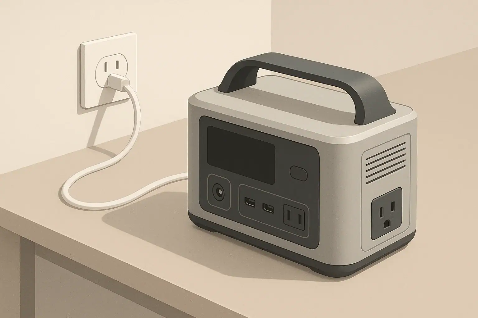
Portable power stations store energy in rechargeable batteries and let you run devices when wall power is not available. Two ideas often get mixed together when people compare models: how fast the battery can be charged, and how long the battery will last over months and years. The connection between the two is largely governed by something called the C-rate.
C-rate is a way to describe how quickly a battery is charged or discharged relative to its capacity. A 1C charge rate means charging a battery from empty to full in about one hour in theory. A 0.5C rate would take about two hours, and 2C would be about half an hour. Real charge times are longer because charging slows down as the battery approaches full, but the C-rate gives a useful comparison point.
For portable power stations, higher C-rate charging can mean less time plugged into the wall, car, or solar, which is helpful during short stops or power outages. However, regularly pushing batteries at very high C-rates can increase heat and stress, which may reduce long-term battery health. Understanding C-rate helps you balance fast charging convenience with reasonable expectations for battery life.
Instead of chasing the highest advertised charging speed, it is more practical to understand how C-rate, capacity, and your actual usage fit together. That way, you can tell whether a power station will realistically recharge between uses and how hard you are asking the battery to work.
What fast charging and C-rate really mean for portable power stations
Portable power stations store energy in rechargeable batteries and let you run devices when wall power is not available. Two ideas often get mixed together when people compare models: how fast the battery can be charged, and how long the battery will last over months and years. The connection between the two is largely governed by something called the C-rate.
C-rate is a way to describe how quickly a battery is charged or discharged relative to its capacity. A 1C charge rate means charging a battery from empty to full in about one hour in theory. A 0.5C rate would take about two hours, and 2C would be about half an hour. Real charge times are longer because charging slows down as the battery approaches full, but the C-rate gives a useful comparison point.
For portable power stations, higher C-rate charging can mean less time plugged into the wall, car, or solar, which is helpful during short stops or power outages. However, regularly pushing batteries at very high C-rates can increase heat and stress, which may reduce long-term battery health. Understanding C-rate helps you balance fast charging convenience with reasonable expectations for battery life.
Instead of chasing the highest advertised charging speed, it is more practical to understand how C-rate, capacity, and your actual usage fit together. That way, you can tell whether a power station will realistically recharge between uses and how hard you are asking the battery to work.
Key concepts and sizing logic: watts, watt-hours, and C-rate
When planning a portable power setup, it helps to separate three basic ideas: power, energy, and charge rate. Power is measured in watts (W) and describes how quickly energy is being used at a moment in time. Energy capacity is measured in watt-hours (Wh) and describes how much total work the battery can do before it needs to be recharged. C-rate ties the two together when you look at how quickly that stored energy moves in or out of the battery.
Battery capacity in watt-hours tells you how long a load can run in theory. For example, a 500 Wh battery feeding a 100 W load could supply that load for about 5 hours: 500 Wh divided by 100 W equals 5 hours. In practice, inverter losses, internal resistance, and other inefficiencies reduce this runtime. A reasonable planning assumption is that you may see 80–90% of the rated watt-hour capacity delivered to AC outlets, depending on how heavily they are loaded.
C-rate uses the battery’s amp-hour (Ah) rating to express charge or discharge current relative to size, but you can think of it in watt-hour terms for power stations. If a 500 Wh battery is being charged at 250 W, that is roughly a 0.5C charge rate: at that pace, a full empty-to-full charge would take about two hours in an ideal case. If the same battery were charged at 500 W, that would be about 1C. Higher C-rate means higher power moving through the system, which increases heat and may require the power station’s fans to run more often.
Inverter ratings add another important layer: the continuous (running) watt rating and the surge (peak) watt rating. The continuous rating is what the inverter can supply steadily. Surge rating describes short bursts to handle motor start-up or inrush current, such as from a refrigerator compressor or power tool. Running devices close to the continuous rating tends to reduce efficiency and increase heat, which also affects effective C-rate on discharge and can shorten runtime.
| Scenario | Example battery size | Example charge power | Approx. C-rate | What this usually means |
|---|---|---|---|---|
| Occasional home backup for small essentials | 500–700 Wh | 150–250 W | 0.2C–0.5C | Slower charges, gentler on battery, easier on household circuits |
| Daily remote work and electronics | 700–1200 Wh | 250–400 W | 0.3C–0.6C | Balanced charge time and battery stress for regular use |
| Frequent fast top-offs between errands | 300–600 Wh | 300–600 W | 0.5C–1C | Shorter charge windows, more fan noise and heat |
| RV or vanlife with solar emphasis | 1000–2000 Wh | 200–600 W solar | ~0.1C–0.3C mid-day | Longer charge cycles, more battery-friendly if shaded heat is managed |
| High-demand tools used briefly | 700–1500 Wh | 400–800 W wall charging | 0.3C–0.8C | Need faster recharge, but avoid using maximum rate constantly |
| Emergency-only, long shelf life priority | 300–1000 Wh | 100–200 W | 0.1C–0.3C | Slower charging, less stress, better for occasional use |
Efficiency losses and real-world charge times
When planning charge time, it is helpful to remember that power stations are not 100% efficient. Some power is lost as heat in the AC adapter or built-in charger, in the battery’s internal resistance, and in the inverter if it is running during pass-through use. A simple rule of thumb is that you may need 10–25% more watt-hours from the wall than the battery’s rated capacity to fill it from low to full.
Charge curves are also not flat. Most systems charge quickly up to a certain percentage, then taper off to protect the battery as it nears full. That means a power station might go from 20% to 80% much faster than from 80% to 100%. From a C-rate perspective, the initial phase uses a higher effective C-rate, and the final top-off phase uses a lower rate. If you only need enough energy to ride through a short outage or finish a workday, stopping around 80–90% can save time and reduce heat.
Real-world examples of C-rate, fast charging, and runtime
Relating C-rate to real-life situations makes it easier to judge what is “fast enough.” Imagine a portable power station with about 500 Wh of capacity. If it can charge from the wall at about 250 W, that is roughly a 0.5C rate. In simple terms, that means you could go from low to near full in a bit over two hours under typical conditions, allowing for efficiency losses and tapering.
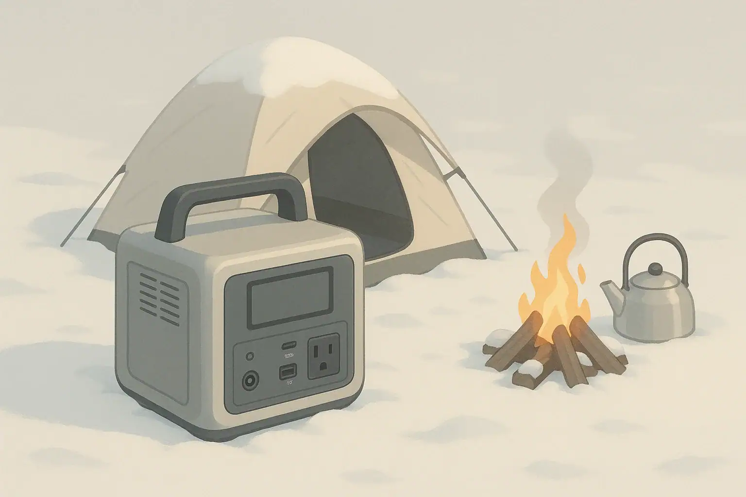
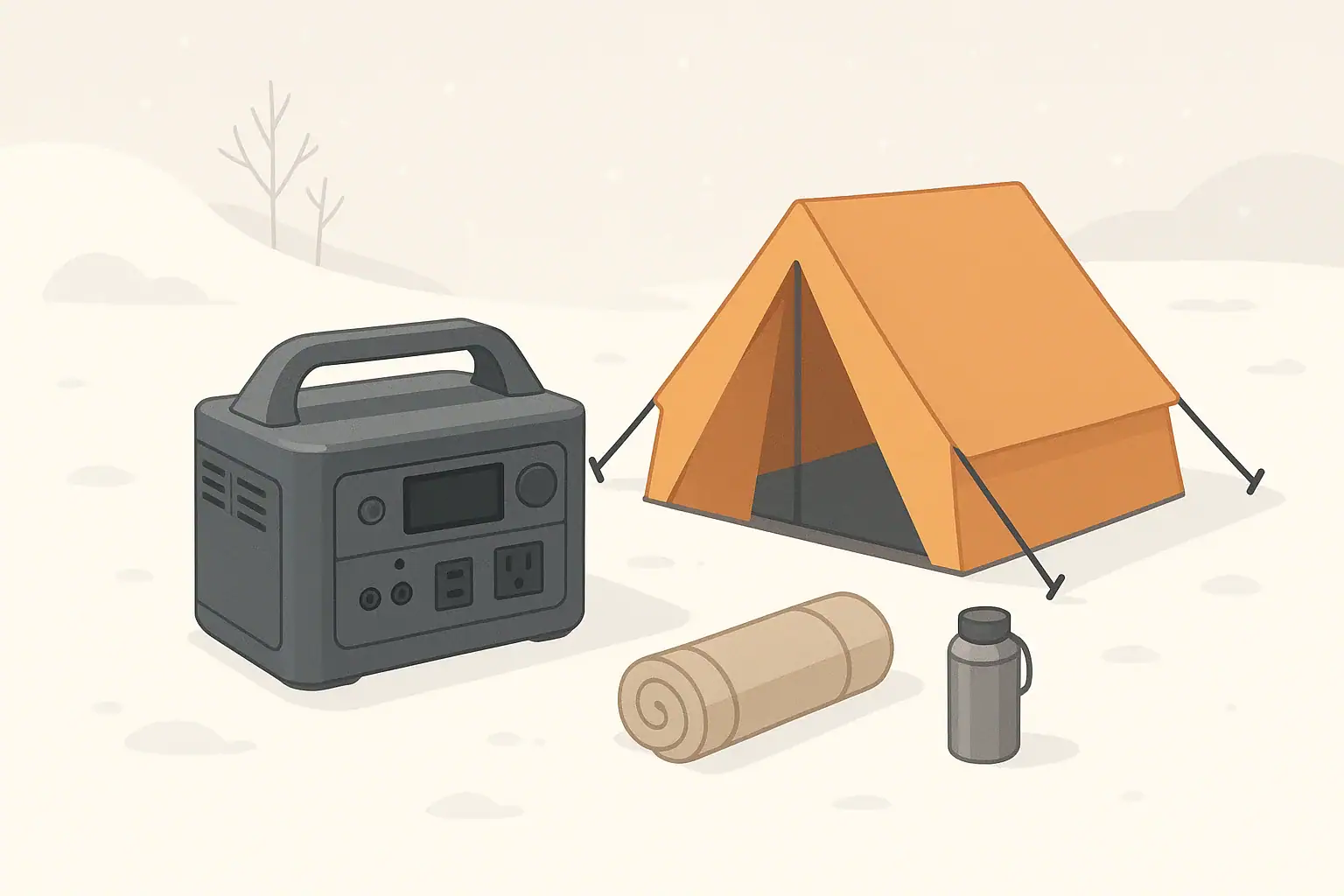
Take that same 500 Wh unit on a camping trip. If you run a 50 W portable fridge and 20 W of lights for 8 hours overnight, that is about 560 Wh of load. Accounting for losses, you might use most of the battery in one night. To be ready for the next evening, you would want to recharge at least 400–500 Wh during the day. With a 250 W wall or generator charger, that might take around 2–3 hours; with a 100 W solar input, it might take most of a sunny day.
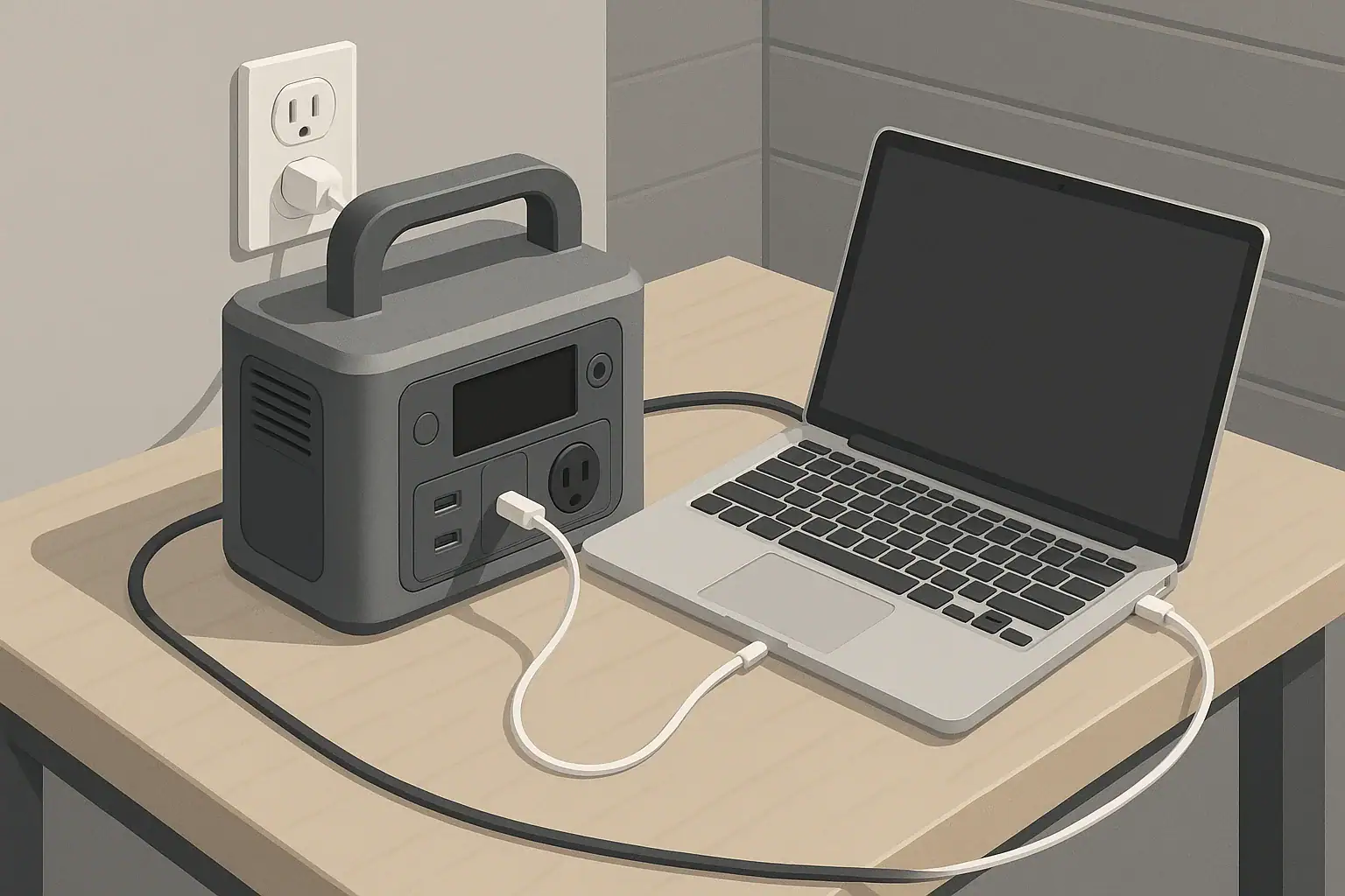
For remote work, consider a 700–1000 Wh power station running a 60 W laptop, 10 W router, and a few watts of phone charging and small accessories. At a 90 W total draw, a 900 Wh battery might deliver around 7–8 hours of runtime once you factor in inverter losses. If that same unit supports 400 W wall charging, you could restore a large portion of that capacity in a long lunch break, operating at around a 0.4C–0.5C charge rate.
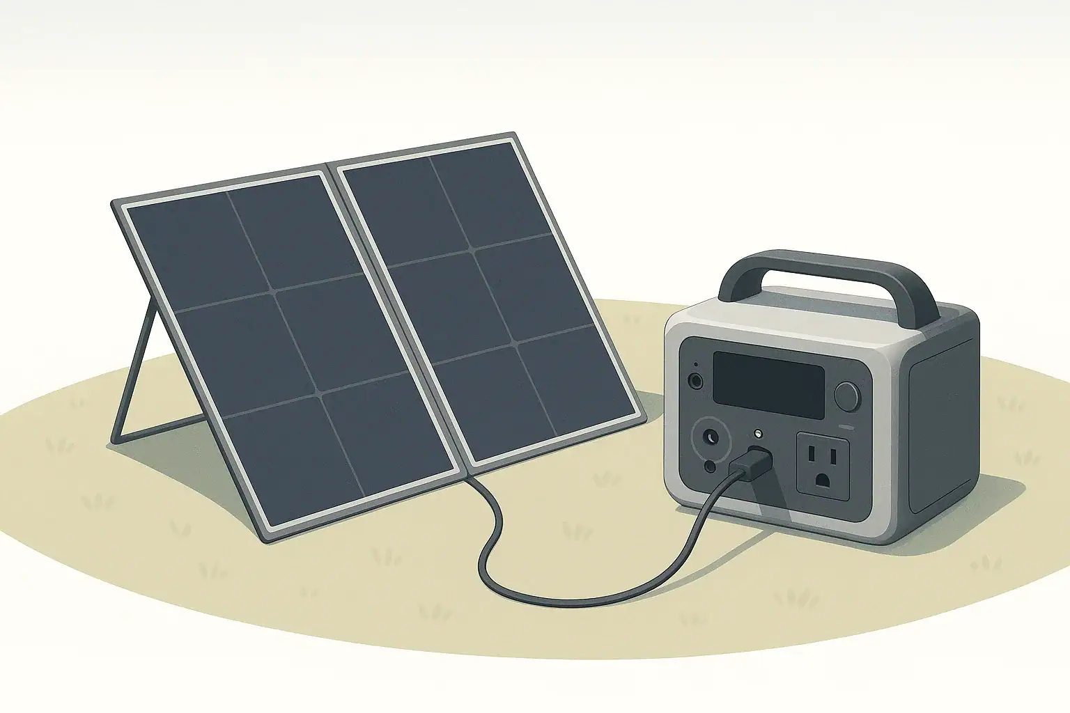
In an RV, a larger 1500–2000 Wh power station might be recharged mainly through solar. Suppose you have 400 W of panels and get about 4–5 effective hours of good sun. That could provide 1600–2000 Wh of input on a clear day, corresponding to roughly a 0.2C–0.3C rate for a 2000 Wh battery. This slower C-rate is gentle on the battery, but you need to manage your loads so that daily use does not consistently exceed daily solar input.
Common mistakes and troubleshooting cues
Many charging and runtime issues come from misunderstandings about C-rate, load size, and what a portable power station is designed to do. One common mistake is assuming the advertised “from 0% to 80% in X minutes” claim applies under all conditions. In reality, temperature, state of charge, and input source (wall vs car vs solar) all influence the actual C-rate the battery sees.
Another frequent issue is overloading the inverter by confusing surge watts with continuous watts. If you plug in a device whose steady draw is close to or above the continuous rating, the power station may shut down or repeatedly trip its protection circuits. Motors, compressors, and some electronics can draw several times their running wattage during startup. If that surge exceeds the inverter’s short-term peak rating, you may see flickering, beeping, or immediate shutdown.
Charging can also slow down or pause when the power station gets hot. Fast charging at a high C-rate, especially in a warm room or vehicle, builds heat quickly. Internal temperature sensors may reduce charge power well below the maximum rating to protect the battery, or even stop charging until the system cools. If you notice the fan running constantly or feel the case getting warm, that is a cue to improve airflow or consider lowering the input power if the device allows it.
Pass-through charging, where the power station is charging while powering devices, can be confusing. If the output load is high, much of the incoming energy is immediately used by the connected devices rather than replenishing the battery. The display may show that it is charging, but the state of charge might climb very slowly or even drop. In extreme cases, the system may throttle charging or shut off outputs to stay within safe C-rate and thermal limits.
Signals your system is being pushed too hard
There are several warning signs that your portable power station is operating at a higher C-rate or load level than it comfortably supports. These are not necessarily failures, but they are cues to reduce stress on the system.
- Fans running at high speed most of the time during charging or heavy use
- Frequent thermal or overload warnings on the display or indicator lights
- Charging power starting high, then dropping sharply after a short time
- Noticeable case warmth, especially near vents or the charging side
- Shorter runtimes than expected at a given load, due to elevated temperatures and losses
When you see these signs, try moving the unit to a cooler, shaded area with better airflow, reducing the load, or allowing the battery to cool before another full-power charge. These simple adjustments can reduce unnecessary battery stress and help preserve long-term capacity.
Safety basics: heat, placement, cords, and GFCI context
Fast charging and high C-rates mean more heat inside a compact enclosure, so placement and ventilation are important. Always use your portable power station in a dry, well-ventilated area where air can move freely around the vents. Avoid covering the unit with blankets, clothing, or gear, and do not place it in enclosed cabinets or tight spaces where hot air cannot escape.
Heat is one of the main factors that shortens battery life. Charging or discharging at high C-rates in hot environments raises internal temperatures and can accelerate aging. Keeping the unit out of direct sun and away from heaters, dashboards, or enclosed vehicle trunks during use and charging can significantly reduce thermal stress. When possible, operate the power station on a firm, non-flammable surface rather than carpets or bedding.
Extension cords and adapters also matter. Undersized or damaged cords can heat up under high loads, especially when running close to the power station’s continuous rating. Use cords rated for at least the maximum current you expect to draw, keep them fully uncoiled to avoid heat buildup, and inspect them regularly for nicks, loose plugs, or discoloration. For outdoor or damp environments, use cords and power strips designed for those conditions.
Many household circuits and outdoor outlets are protected by GFCI devices, which are designed to reduce shock risk in wet or grounded locations. Plugging a portable power station into a GFCI-protected outlet for charging is typically acceptable, but avoid daisy-chaining multiple power strips, cords, and adapters. If you encounter tripping or unusual behavior, disconnect everything and simplify the setup. For any connection involving a building’s wiring beyond standard plug-in use, consult a qualified electrician instead of attempting your own modifications.
Maintenance and storage for long battery life
How you treat a portable power station between uses can matter almost as much as how you charge it. Batteries slowly lose charge even when turned off, a process called self-discharge. The rate varies, but it is normal to see a few percent of charge fade per month. Plan to check the state of charge periodically, especially if the unit is stored for emergencies.
Most lithium-based batteries prefer to be stored partially charged rather than completely full or empty. A common recommendation is to keep long-term storage in the middle range, such as around 40–60% state of charge. This reduces stress on the cells while still keeping enough energy on hand for short-notice use. If you store the unit at a very low charge for too long, the battery may fall below its safe voltage range and the protection circuitry can prevent normal charging.
Temperature during storage is another key factor. Moderate, dry conditions are best. Extremely hot environments, such as attics or parked vehicles in summer, can accelerate aging even when the battery is not in use. Very low temperatures do not usually damage the battery by themselves, but charging at or below freezing can be harmful. If the power station has been stored in the cold, let it warm to room temperature before charging.
Routine checks help you catch small issues before they become larger problems. Inspect cables, wall adapters, and ports for wear or debris. Gently clean dust from vents with a dry cloth or low-pressure air so the cooling system can work properly during high C-rate charging or discharging. Turn the unit on occasionally to verify that the display, ports, and outlets function as expected, especially if you rely on it for backup power.
| Usage pattern | Suggested storage charge level | Check/charge interval | Key maintenance focus |
|---|---|---|---|
| Emergency-only home backup | 40–60% | Every 3–6 months | Top up charge, test a small load, inspect cords and outlets |
| Seasonal camping or RV | 40–70% | Before and after each season | Clean vents, verify solar inputs, confirm charge settings |
| Weekly remote work use | 50–80% between sessions | Weekly | Monitor runtime changes, watch for excess heat or fan noise |
| Daily mobile power (vanlife) | 30–80% cycling | Monthly deep check | Inspect all cables, clean dust, review charging sources and limits |
| Tool and jobsite backup | 50–80% | Monthly or before major jobs | Check inverter output under load, inspect cords for damage |
| Mixed household and travel | 40–70% | Every 2–3 months | Test various ports, ensure adapters and accessories are stored together |
Practical takeaways: balancing fast charging and battery life
Understanding C-rate turns fast charging claims into useful planning tools instead of marketing numbers. Higher C-rate charging and discharging give you flexibility during outages, travel, and short charge windows, but they also increase heat and long-term wear. For most users, a moderate C-rate that refills the battery over a few hours offers a good balance of convenience and longevity.
Rather than focusing only on maximum charging watts, match your portable power station’s capacity and charge rate to your actual loads and schedules. Think about how long you need to run key devices, how much time you have between uses to recharge, and what energy sources you can rely on. Planning with realistic runtimes and charge times will help you avoid surprises when you need power most.
- Size the battery in watt-hours to cover your typical loads with a buffer for inefficiencies.
- View maximum charge power as an upper limit, not a requirement to use at every cycle.
- Watch for signs of thermal stress such as constant fan noise and warm casing during use.
- Store the unit partially charged in a cool, dry place and check it periodically.
- Use appropriate cords and outlets, and avoid stacking adapters or modifying wiring.
- Allow extra time for charging in hot weather or when using pass-through power.
With these habits, you can take advantage of fast charging when it truly helps, while giving the battery conditions that support a long, reliable service life.
Frequently asked questions
What C-rate is recommended for daily charging of a portable power station?
A moderate C-rate around 0.3C–0.6C is a good balance for daily use because it refills most capacity in a few hours without causing excessive heat. Exact safe rates vary by battery chemistry and manufacturer guidance, so follow the unit’s specifications when available.
How does charging at a high C-rate affect long-term battery lifespan?
Higher C-rates increase internal heat and mechanical stress on cells, accelerating capacity loss and reducing cycle life over time. Occasional fast charges are acceptable, but frequent high-C charging will generally shorten the battery’s useful life compared with gentler charging.
How can I estimate real-world charge time from C-rate and watt-hours?
Divide charge power (W) by battery capacity (Wh) to find approximate C-rate (for example, 250 W into 500 Wh ≈ 0.5C). The theoretical empty-to-full time is about 1/C hours, but real-world charging takes longer due to tapering and inefficiencies—add roughly 10–25% extra time and expect the final 10–20% to take disproportionately longer.
Is pass-through charging (charging while powering devices) safe to use often?
Pass-through is typically safe for occasional use, but when loads are high much of the incoming power goes to running devices rather than charging the battery, which raises heat and can trigger throttling. Frequent pass-through at high loads or in warm conditions can increase wear and reduce battery lifespan.
What signs show my power station is being charged too fast?
Look for constant high fan speed, thermal or overload warnings, rapid drops in displayed charge power, and a noticeably warm case near vents—these indicate heat-related stress or throttling. If observed, reduce input power, improve ventilation, or allow the unit to cool before further high-rate charging.
Can solar fast-charging deliver high C-rates safely for portable power stations?
Solar can provide substantial charge power, but effective C-rate depends on panel wattage, sun conditions, and the station’s charge controller. High daytime solar input spread over several hours is usually gentle, but pairing large solar input with hot temperatures or a small battery can raise internal temperatures and accelerate wear, so use MPPT control and manage ventilation.
Recommended next:
- USB-C Power Delivery (PD) Explained for Portable Power Stations
- Charging From a Car: What’s Safe, What’s Slow, and What Can Break
- Input Limits (Volts/Amps/Watts) Explained: How Not to Damage Your Unit
- MPPT vs PWM in Portable Power Stations: What It Changes in Real Life
- Can You Use a Higher-Watt Charger Than Rated? Understanding Input Headroom
- Why Charging Slows Down Near 80–100%: A Simple Explanation
- More in Charging →