What the topic means and why cable condition matters
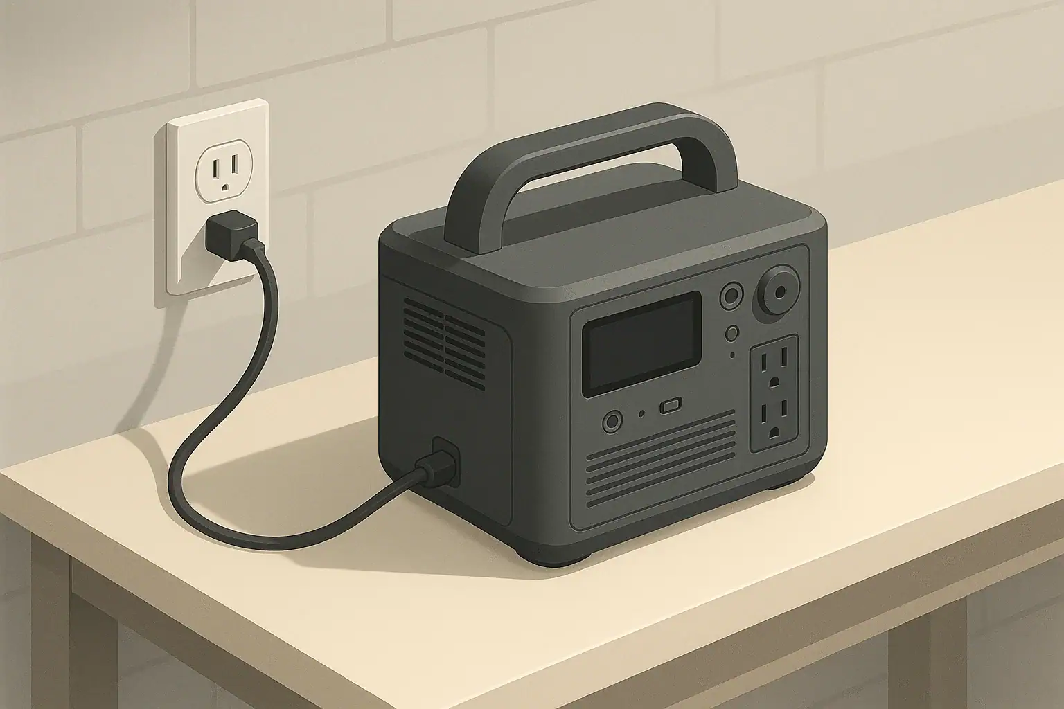
Portable power stations depend on a network of cables and adapters to move energy safely between the battery, the wall outlet, solar panels, vehicles, and your devices. Over time, those cords, plugs, and adapters experience wear, bending, and heat. Knowing when to replace them is an important part of using a power station safely and getting consistent performance.
In this context, cables include AC power cords, DC car-style leads, solar input cables, and USB or other low-voltage leads. Adapters include AC wall bricks, plug converters, and small in-line modules that step voltage up or down. These components are designed with specific current and voltage ratings, and they also act as part of the safety system for your portable power station.
As cables age, insulation can crack, connectors can loosen, and resistance can increase. All of these can create excess heat, reduce charging speed, or cause intermittent shutdowns. In more serious cases, damaged cables and overheating adapters can present a shock or fire risk, especially when used with high-power loads or in confined, poorly ventilated spaces.
Replacing worn or overheating cables and adapters at the right time helps maintain reliable runtime estimates, protects your power station’s battery, and reduces the chance of nuisance tripping or unexpected shutdowns. It also supports safer operation during power outages, camping, RV travel, and everyday remote work setups.
Key concepts and sizing logic for safe cabling
Understanding how power flows through cables and adapters helps you recognize when a component is undersized, stressed, or due for replacement. Portable power stations are typically described using watt-hours (Wh) for capacity and watts (W) for output. Cables and adapters must be sized to carry the maximum expected watts safely, considering both steady and short-term surge loads.
Watts describe the rate of energy use or delivery, while watt-hours describe how much energy is stored. For example, if a device draws 100 W, running it for 5 hours uses roughly 500 Wh. Cables must handle the current that corresponds to those watts at a given voltage. In the U.S., AC outlets are usually 120 V; a 600 W load at 120 V draws about 5 A. On the DC side, the same 600 W might require much higher current at a lower voltage, which stresses cables more if they are undersized or damaged.
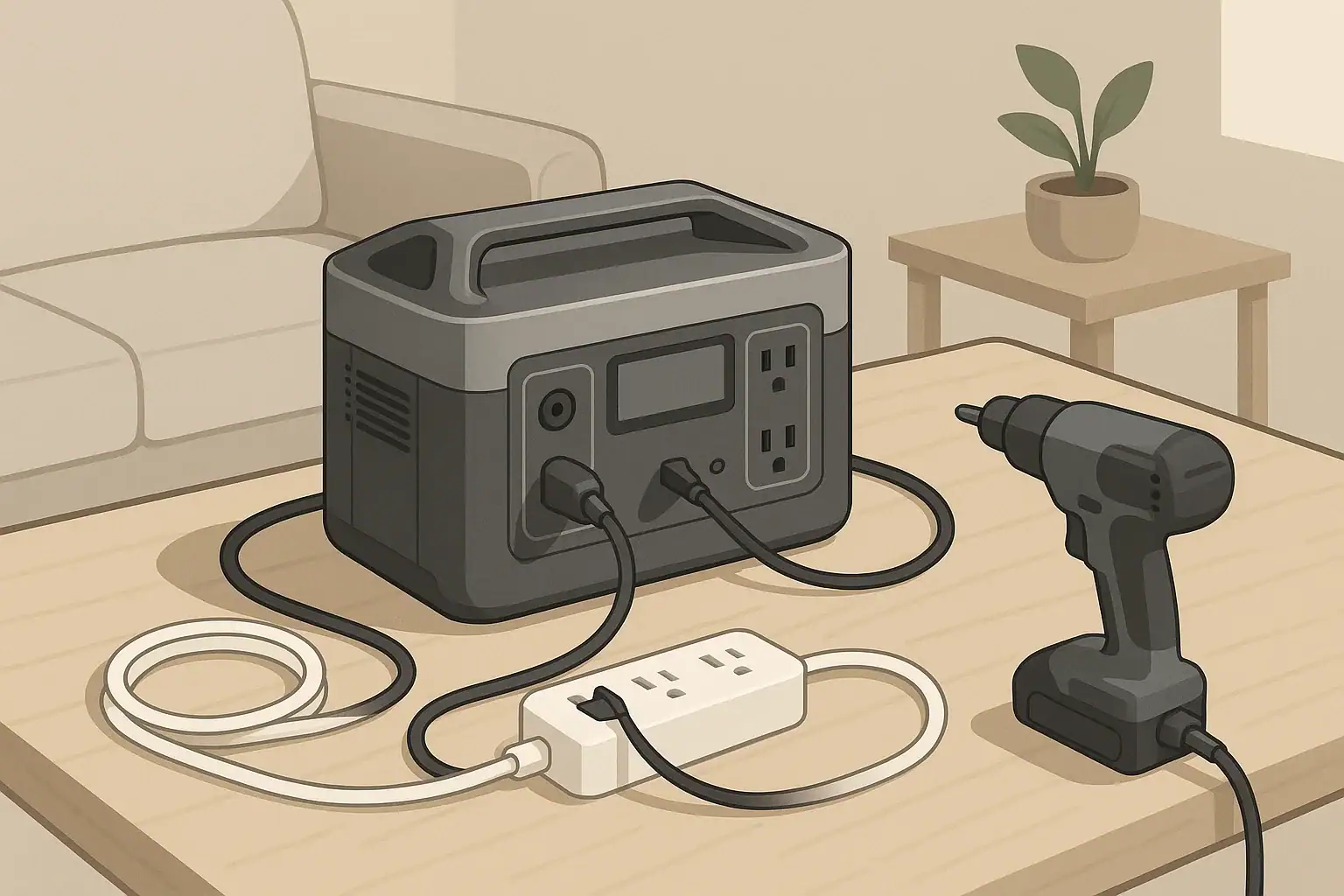
Many devices have higher surge wattage when starting up, such as refrigerators, pumps, or certain power tools. Surge can temporarily double or even triple current through the cable. If the cord is thin, excessively long, or worn, that extra current can create noticeable heating in both the cable and adapters. This heat is a sign of energy lost as resistance, not useful work, and it can accelerate wear or damage connectors over time.
Inverters and adapters also introduce efficiency losses, which means more power is drawn from the battery than the device actually consumes. Typical portable systems may lose 10–20% converting DC battery power to AC, or when stepping voltage up or down. That extra energy turns into heat in the electronics and cables. When a cable or brick-style adapter is already close to its limit, these losses can push it into persistent overheating, signaling that it may be undersized for the way it is being used or that it has degraded and needs attention.
| What to check | Why it matters | Example cue to replace |
|---|---|---|
| Cable jacket and insulation | Protects conductors from shorts and shock | Cracks, cuts, or exposed metal visible |
| Connector fit at both ends | Loose plugs increase resistance and heat | Wiggling plug causes power loss or sparks |
| Heat during typical use | Overheating indicates stress or undersizing | Too hot to hold comfortably for several seconds |
| Discoloration and odor | Burn marks or smell can signal past overloads | Browned plastic or persistent burnt-plastic smell |
| Strain reliefs at plug ends | Prevents internal wire breakage from bending | Frayed or separated strain relief, kinked area |
| Labeling and ratings | Confirms cable is matched to voltage and current | Unknown ratings for high-power or long-term use |
| Age and usage history | Heavy daily use wears connectors faster | Several years of constant flexing or coiling |
Real-world examples of wear, overheating, and right-sizing
Consider a portable power station running a 300 W home office setup, including a laptop, monitor, and networking gear. On the AC side at 120 V, the current is only a few amps, well within the rating of a typical grounded extension cord. If the cord is in good condition, it may feel warm at most but not hot. However, a thin, older cord with worn insulation and loose plugs can develop hot spots, showing that resistance has increased and that the cord is approaching the end of its useful life.
For camping or RV use, a portable power station might supply a small 500 W appliance, such as an induction cooktop at low power or a compact heater used briefly. The AC cable between the power station and the appliance experiences higher current and heat than with lighter loads. If that cable is repeatedly coiled tightly while still warm, the insulation can harden or crack over time. You may first notice this as a stiff section near the plug or faint discoloration. When you see these clues, replacing the cable is safer than continuing to push it with high-load use.
On the DC and solar side, imagine a 12 V car charging cable delivering around 120 W from the vehicle to the power station while driving. That level of power requires roughly 10 A of current, so cable thickness and connector quality are more critical. If the plug at the vehicle outlet runs noticeably hot, or if the plastic shell deforms slightly, it may indicate that the plug is undersized, partially loose, or worn. Upgrading to a properly rated cable or replacing a tired adapter is a preventive step that reduces the risk of failure on long trips.
Solar input cables present a different pattern of wear. They are exposed to sun, temperature swings, and movement. The outer jacket can fade, become brittle, or split where the cable exits the connector. Even if these cables do not feel hot, visual signs of UV damage or cracking are enough reason to replace them, since water or conductive dust entering damaged areas could cause intermittent faults or reduced charging efficiency.
Common mistakes and troubleshooting cues with cables and adapters
One common mistake is using an extension cord or adapter that is thinner or lower-rated than the portable power station’s output. When the station is asked to power space heaters, coffee makers, or other high-demand appliances, an undersized cord may overheat even if the power station itself is operating within its limits. If you notice the cord getting significantly hotter than the power station body, or if the plug feels soft or smells like hot plastic, that is a cue to stop use and replace the cord with one properly rated for the load.
Another frequent issue is daisy-chaining multiple adapters, such as stacking plug converters, using power strips on the station’s AC output, or connecting several USB adapters into a single outlet. Every extra connection adds resistance and another possible failure point. Flickering power, devices unexpectedly disconnecting, or the power strip’s plug becoming very warm are signs that the chain of adapters is too complex for the combined load, and simplifying the setup can both improve reliability and reduce cable wear.
Charging that suddenly slows or stops can also be related to cables and adapters. For example, a portable power station charged via a wall adapter or USB-C input might show reduced charge rates if the cable’s internal conductors are partially broken. You may see charging resume when you hold the cable at a certain angle, or randomly disconnect if the cable is bumped. These behaviors indicate internal fatigue or connector damage even if the outer jacket appears intact. Replacing the cable is usually more effective than repeatedly repositioning it.
Unexpected shutdowns under load can stem from voltage drop along long or undersized cables, especially on DC circuits. As current increases, resistance in the cable causes the voltage at the device end to sag. The power station may sense this as an overload or fault and shut down to protect itself. If a device runs fine when plugged directly into the station but not when using a long cord, that cord may be too small or worn. Shorter, thicker, or newer cables often resolve the issue and reduce waste heat in the wiring.
Safety basics: placement, ventilation, cords, and heat
Safe use of cables and adapters with portable power stations begins with placement. Keep the power station on a stable, dry, nonflammable surface with enough space around it for ventilation. Avoid covering the unit or resting heavy items on cables and adapters, since crushed or pinched cords can overheat. When running cables across a room, route them where they will not be walked on, pinched in doors, or trapped under rugs for extended periods.
Ventilation matters not only for the power station’s internal electronics but also for adapters like AC bricks and DC chargers. These components are designed to shed heat into the surrounding air. If they are buried under blankets, placed on soft bedding, or wedged behind furniture, heat can build up. Warm to the touch is normal under load, but if you cannot comfortably keep your hand on the adapter for several seconds, disconnect it and let it cool. Persistent excessive heat is a signal to reconsider placement or replace the adapter.
Cord selection is also a safety consideration. For higher-power AC loads in the U.S., grounded three-wire cords that match or exceed the expected current rating are generally preferred. For outdoor or damp environments, use cords that are rated for the conditions, keeping all connections off the ground when possible. High-level ground-fault protection, such as using outlets that incorporate ground-fault circuit interrupter (GFCI) technology, can provide additional protection around moisture, although the exact setup will depend on where and how you are using the power station.
For any connection involving household wiring, outbuildings, or RV shore power systems, it is important not to improvise custom cords or bypass built-in protections. Avoid any attempt to backfeed a home electrical panel or modify fixed wiring using a portable power station. High-level guidance is simply to keep the power station and its cords separate from permanent electrical systems unless a qualified electrician has installed an appropriate, code-compliant interface. This reduces both shock and fire risks while preserving the safety features that come with modern equipment.
Maintenance and storage for longer-lasting cables and adapters
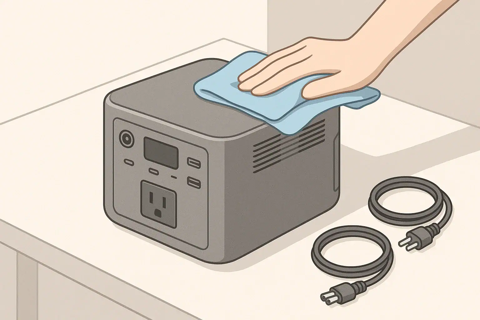
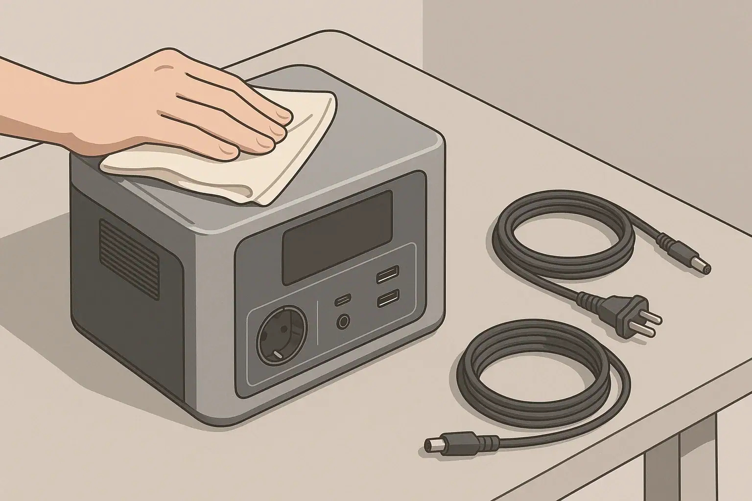
Routine care helps cables and adapters last longer and reduces the chance of overheating. After high-load use, allow cords and adapters to cool before tightly coiling or packing them away. Inspect them periodically for nicks, flattened sections, or areas that feel stiffer than the rest of the cable, as these can mark internal damage. Dust and debris cleaning off vents and connectors with a dry cloth can also improve heat dissipation and contact quality.
When storing a portable power station and its accessories, moderate temperatures and low humidity are preferred. Extreme heat can accelerate insulation breakdown and connector corrosion, while extreme cold can make cable jackets brittle and prone to cracking when bent. A cool, dry room is usually ideal. Avoid placing heavy items on coiled cords, and do not hang adapters from their cables, as this can stress the internal connections over time.
Battery self-discharge affects how often you use your charging cables and adapters. Many portable power stations hold a charge reasonably well, but it is still good practice to check the state of charge every few months during storage. When you top up the battery, use the original or properly rated charging cable and monitor for unexpected heating or noise from the adapter. If the brick hums unusually, emits an odor, or runs hotter than you remember under similar conditions, consider replacing it.
Cold-weather use introduces additional stress. In low temperatures, cable insulation and jackets can harden, and repeatedly flexing cold cords can lead to micro-cracks. When possible, warm cables gently to room temperature before tightly coiling them, and avoid sharp bends in freezing conditions. Periodic visual inspections at the start and end of each season can catch early signs of wear, allowing you to retire questionable cables before they fail during a critical outage or trip.
| Maintenance task | Suggested frequency | What to look or feel for |
|---|---|---|
| Visual cable inspection | Every 3–6 months | Cracks, cuts, abrasions, discoloration |
| Connector and plug check | Before long trips or outages | Loose fit, wobble, burn marks |
| Heat check under normal load | During first use after storage | Too hot to hold, softening plastic |
| Dust and debris cleaning | Every 6–12 months | Dust around vents and connectors |
| Re-coiling and storage review | Each time you pack up | Kinks, tight bends, crushed spots |
| Cold-weather inspection | Start and end of winter season | Brittle feel, jacket cracking |
| Adapter performance review | Annually | New noises, odors, or excess heat |
Example values for illustration.
Practical takeaways and replacement checklist
Deciding when to replace cables and adapters for your portable power station comes down to observing physical condition, monitoring heat, and paying attention to performance changes. Visible damage, persistent overheating, or unreliable connections are all clear signs to retire a component, especially when you rely on your setup for critical needs during outages or while traveling.
Keeping a small inventory of known-good spare cords and adapters can reduce downtime and simplify troubleshooting. When a device behaves unpredictably, swapping in a fresh cable is a quick way to rule out common problems. If replacing a cable resolves heat or shutdown issues, it confirms that the old component had reached the end of its safe life.
Use this non-exhaustive checklist as a practical reference:
- Replace any cable with cracks, cuts, exposed metal, or melted areas.
- Retire cords or adapters that are too hot to hold under normal use.
- Stop using plugs that spark, wiggle excessively, or show burn marks.
- Avoid chaining multiple adapters and using thin cords for high-power loads.
- Store cables loosely coiled in a cool, dry place without heavy items on top.
- Inspect solar and outdoor cables regularly for UV damage and brittleness.
- If performance issues disappear with a new cable, do not return to the old one.
By pairing these habits with appropriate sizing and placement, you help ensure that your portable power station and its accessories operate safely and consistently, whether you are backing up essential home loads, working remotely, or spending time off-grid.
Frequently asked questions
What visible signs mean I should immediately replace a cable or adapter?
Replace a cable or adapter immediately if you see cracks, cuts, exposed metal, melted plastic, brown discoloration, or smell persistent burning. Also stop use and replace if plugs wiggle excessively, spark, or the connector housing is deformed, since these indicate increased resistance or internal damage.
How hot is “too hot” before I should replace cables and adapters?
Warmness under load is normal, but a cable or adapter is too hot if you cannot comfortably keep your hand on it for several seconds or if the plastic softens. Sustained high temperature, softening, or charring are signs the component is overstressed or failing and should be replaced.
My cable charges intermittently and works when I hold it at a certain angle—should I replace it?
Yes. Intermittent charging or needing to hold a cable in a specific position usually indicates internal conductor fatigue or connector damage that can worsen suddenly. Replacing the cable is safer and more reliable than continuing to use a partially broken lead.
How often should I inspect and consider replacing cables and adapters used with a portable power station?
Perform a visual inspection every 3–6 months and check connectors before long trips or critical outages; review adapter performance annually or more often with heavy use. Replace components based on condition—sooner if you notice heat, looseness, odor, or physical damage.
Can I repair a frayed or damaged cable, or should I replace cables and adapters?
For safety-critical or high-power cables, avoid DIY repairs—tape or splices may hide damage but do not restore conductor integrity and can create fire risks. Replace with a properly rated cable or have a qualified technician repair low-voltage, non-critical items when appropriate.
Recommended next:
- How to Clean and Inspect Ports, Cables, and Fans (Without Causing Damage)
- Long-Term Storage Best Practices: Charge Level, Temperature, and Schedule
- Should You Leave a Power Station Plugged In All the Time?
- How to Test Real Capacity at Home: A Simple Step-by-Step Method
- Firmware Updates and App Control: What to Expect (and What to Avoid)
- More in Maintenance →